EP0897071A2 - Frein à disque - Google Patents
Frein à disque Download PDFInfo
- Publication number
- EP0897071A2 EP0897071A2 EP98115171A EP98115171A EP0897071A2 EP 0897071 A2 EP0897071 A2 EP 0897071A2 EP 98115171 A EP98115171 A EP 98115171A EP 98115171 A EP98115171 A EP 98115171A EP 0897071 A2 EP0897071 A2 EP 0897071A2
- Authority
- EP
- European Patent Office
- Prior art keywords
- brake
- bracket
- spindle
- axis
- lever
- Prior art date
- Legal status (The legal status is an assumption and is not a legal conclusion. Google has not performed a legal analysis and makes no representation as to the accuracy of the status listed.)
- Withdrawn
Links
- 230000008878 coupling Effects 0.000 claims description 3
- 238000010168 coupling process Methods 0.000 claims description 3
- 238000005859 coupling reaction Methods 0.000 claims description 3
- 238000009423 ventilation Methods 0.000 description 3
- 230000000712 assembly Effects 0.000 description 1
- 238000000429 assembly Methods 0.000 description 1
- 230000000750 progressive effect Effects 0.000 description 1
Images


Classifications
-
- B—PERFORMING OPERATIONS; TRANSPORTING
- B66—HOISTING; LIFTING; HAULING
- B66D—CAPSTANS; WINCHES; TACKLES, e.g. PULLEY BLOCKS; HOISTS
- B66D5/00—Braking or detent devices characterised by application to lifting or hoisting gear, e.g. for controlling the lowering of loads
- B66D5/02—Crane, lift hoist, or winch brakes operating on drums, barrels, or ropes
- B66D5/12—Crane, lift hoist, or winch brakes operating on drums, barrels, or ropes with axial effect
- B66D5/14—Crane, lift hoist, or winch brakes operating on drums, barrels, or ropes with axial effect embodying discs
-
- F—MECHANICAL ENGINEERING; LIGHTING; HEATING; WEAPONS; BLASTING
- F16—ENGINEERING ELEMENTS AND UNITS; GENERAL MEASURES FOR PRODUCING AND MAINTAINING EFFECTIVE FUNCTIONING OF MACHINES OR INSTALLATIONS; THERMAL INSULATION IN GENERAL
- F16D—COUPLINGS FOR TRANSMITTING ROTATION; CLUTCHES; BRAKES
- F16D55/00—Brakes with substantially-radial braking surfaces pressed together in axial direction, e.g. disc brakes
- F16D55/02—Brakes with substantially-radial braking surfaces pressed together in axial direction, e.g. disc brakes with axially-movable discs or pads pressed against axially-located rotating members
- F16D55/22—Brakes with substantially-radial braking surfaces pressed together in axial direction, e.g. disc brakes with axially-movable discs or pads pressed against axially-located rotating members by clamping an axially-located rotating disc between movable braking members, e.g. movable brake discs or brake pads
- F16D55/224—Brakes with substantially-radial braking surfaces pressed together in axial direction, e.g. disc brakes with axially-movable discs or pads pressed against axially-located rotating members by clamping an axially-located rotating disc between movable braking members, e.g. movable brake discs or brake pads with a common actuating member for the braking members
- F16D55/2245—Brakes with substantially-radial braking surfaces pressed together in axial direction, e.g. disc brakes with axially-movable discs or pads pressed against axially-located rotating members by clamping an axially-located rotating disc between movable braking members, e.g. movable brake discs or brake pads with a common actuating member for the braking members in which the common actuating member acts on two levers carrying the braking members, e.g. tong-type brakes
-
- F—MECHANICAL ENGINEERING; LIGHTING; HEATING; WEAPONS; BLASTING
- F16—ENGINEERING ELEMENTS AND UNITS; GENERAL MEASURES FOR PRODUCING AND MAINTAINING EFFECTIVE FUNCTIONING OF MACHINES OR INSTALLATIONS; THERMAL INSULATION IN GENERAL
- F16D—COUPLINGS FOR TRANSMITTING ROTATION; CLUTCHES; BRAKES
- F16D65/00—Parts or details
- F16D65/14—Actuating mechanisms for brakes; Means for initiating operation at a predetermined position
- F16D65/16—Actuating mechanisms for brakes; Means for initiating operation at a predetermined position arranged in or on the brake
- F16D65/18—Actuating mechanisms for brakes; Means for initiating operation at a predetermined position arranged in or on the brake adapted for drawing members together, e.g. for disc brakes
- F16D65/183—Actuating mechanisms for brakes; Means for initiating operation at a predetermined position arranged in or on the brake adapted for drawing members together, e.g. for disc brakes with force-transmitting members arranged side by side acting on a spot type force-applying member
Definitions
- the invention relates to a disc brake according to the preamble of claim 1.
- a disc brake of this type it is known the articulation axis the spindle on the bracket between the joint axes to arrange the brake lever ends, the articulation axis of the Spindle under the connecting line between the joint axes is at the brake lever ends.
- the bracket is raised by an electro-hydraulic ventilator is pivoted, the pivot axis of the spindle moves around the Hinge axis on the closest brake lever upwards with enlargement the distance between the two brake lever ends.
- the bracket is closed by a spring assembly to close the brake pivoted down into the horizontal position, the articulation axis the spindle while reducing the distance between the joint axles at the brake lever ends like a Eccentric around the hinge axis of the nearest brake lever is pivoted.
- the spring assembly grips approximately in the middle between the two brake levers on a side shoulder of the bracket.
- Disc brakes of this type are used, for example, in crane systems intended. A high braking force is important here.
- the invention has for its object a disc brake to improve the type specified so that with simple Means an increase in braking force is achieved.
- 1 and 3 are 1 and 2 opposite to each other Brake lever designated, with the lower ends at 3 and 4 respectively are hinged to a base 5.
- a brake shoe In the middle of the two Brake lever 1,2 is a brake shoe via a pivot pin 6 or 6 'articulated.
- the brake lever 2 is at the top via a pivot pin with pivot axis 8 with a spindle 7 connected with a pivot pin with articulation axis 9 with a bracket 10 is connected to which via a hinge pin articulated with the hinge axis 11 of the upper end of the brake lever 1 is.
- the Bracket 10 the two upper ends of the brake lever 1, 2, on 1, free left end of the bracket 10, a spring assembly 12 attacks, the other end of which is connected to the base 5.
- This spring assembly 12 acts in the closing direction of the brake, i.e. the bracket 10 is by the spring assembly 12 in the in Fig. 1st reproduced closed position pulled down.
- On the opposite side is another spring assembly 12 'between Base 5 and bracket 10 arranged, which is also in Closing direction acts and the right end of the bracket 10 after presses up.
- FIG. 2 there is an electrohydraulic at the base 5 Device 13 hinged to a side extension 14 of the Bracket 10 attacks articulated and by means of which the bracket 10 the closed position shown, in which the brake shoes 6, 6 'on the brake disc 15 indicated in FIG. 2, in the opening position is pivoted upwards, in which the two upper ends of the brake lever 1, 2 moved away from each other become.
- the articulation axis 9 of the spindle 7 on the bracket 10 lies in the view of FIGS. 1 and 3 at a distance on the outside of the hinge pin with the hinge axis 11 between Brake lever 1 and bracket 10. If the bracket 10 from the in Fig.
- the connecting line forms an angle of approximately between the axes 9 and 11 4 to 8 ° with the connecting line between the joint axes 8 and 11 in the closed position shown in FIG Brake.
- the horizontal distance between axes 9 and 11 can be around 60mm.
- the hinge pin with the articulation axis 9 acts in this arrangement relative to the pivot pin with the axis 11 as an eccentric, by pivoting the bracket 10 from the open position down into the closed position the effective lever is enlarged becomes.
- considerably higher braking forces can be applied be than in the known embodiment in which the Articulation axis 9 on the inside of the hinge axis 11, ie inside the distance between the joint axes 8 and 11 lies.
- 1 and 3 results in the arrangement when closing the brake, a leverage ratio of 1:30 to 1:34, while opening a leverage ratio of about 1:16 results.
- the arrangement described the braking force almost doubled compared to the known design become.
- the Brake levers 1 and 2 When placing the brake shoes on the brake disc, the Brake levers 1 and 2 only moved a short way, for example in each case by 0.337 ° around the lower articulation points 3 and 4 pivoted inwards.
- the bracket 10 is made the open position shown in dashed lines in FIG. 3 by approximately 15.5 ° pivoted below into the horizontal position, at the same time the hinge axis 11 moves somewhat inwards, as if pulled out Lines indicated in Fig. 3.
- the two brake levers 1 and 2 are preferred at the lower ends supported against one another via a rotary coupling 16, a cylinder welded to the brake lever 1, for example that engages in a groove on the opposite brake lever 2.
- This rotary coupling 16 ensures when opening the Brake lever has an even air gap between the brake disc and brake shoes.
- each brake lever by two spaced, parallel, plate-shaped Brake lever parts 21 formed, via connecting elements 17 form a unit.
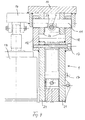
- Fig. 4 shows a section through the articulated connection between brake lever 1 and bracket 10, the two spaced Tabs 20 is provided, in which the pivot pin with the Joint axis 11 is attached.
- On the outside of the two Brake lever parts 21 of the brake lever 1 are extension parts 18 welded, in which the tabs 20 to the outside projecting ends of the pivot pin are rotatably mounted.
- the hinge pin itself, as shown in FIG. 4, has a recess 23 provided, through which the spindle 7, which in the view of FIG. 1 through the cross section of the hinge pin runs with the hinge axis 11.
- a linkage adjustment device shown at 19 in FIG be attached when worn the brake lining of the brake shoes automatically the specified Air gap readjusted.
- the spring assemblies 12 and 12 ' are preferably in the middle between the two brake lever parts or in the plane of the Brake levers 1 and 2 arranged, as shown in FIGS. 2 and 5.
- Fig. 5 shows the articulation of the spring assembly 12 on the side of the brake lever 2.
- the between the brake lever parts 21 on the spring assembly 12 is arranged on a hinge pin 24 attached, the ends in tabs of the bracket 10th are stored.
- the bracket 10 is U-shaped, so that the entire top of the brake covered by the bracket 10 becomes.
Landscapes
- Engineering & Computer Science (AREA)
- General Engineering & Computer Science (AREA)
- Mechanical Engineering (AREA)
- Braking Arrangements (AREA)
Applications Claiming Priority (2)
| Application Number | Priority Date | Filing Date | Title |
|---|---|---|---|
| DE19735127A DE19735127C1 (de) | 1997-08-13 | 1997-08-13 | Scheibenbremse |
| DE19735127 | 1997-08-13 |
Publications (2)
| Publication Number | Publication Date |
|---|---|
| EP0897071A2 true EP0897071A2 (fr) | 1999-02-17 |
| EP0897071A3 EP0897071A3 (fr) | 2001-09-19 |
Family
ID=7838885
Family Applications (1)
| Application Number | Title | Priority Date | Filing Date |
|---|---|---|---|
| EP98115171A Withdrawn EP0897071A3 (fr) | 1997-08-13 | 1998-08-12 | Frein à disque |
Country Status (2)
| Country | Link |
|---|---|
| EP (1) | EP0897071A3 (fr) |
| DE (1) | DE19735127C1 (fr) |
Cited By (2)
| Publication number | Priority date | Publication date | Assignee | Title |
|---|---|---|---|---|
| FR2826417A1 (fr) * | 2001-06-20 | 2002-12-27 | Sime Stromag Sas | Frein a disque notamment pour usage industriel |
| CN119591006A (zh) * | 2024-12-27 | 2025-03-11 | 浙江三一装备有限公司 | 一种卷扬机制动控制系统、方法和起重机 |
Families Citing this family (5)
| Publication number | Priority date | Publication date | Assignee | Title |
|---|---|---|---|---|
| RU2292497C1 (ru) * | 2005-07-11 | 2007-01-27 | Открытое акционерное общество "АВТОВАЗ" | Тормозной механизм |
| DE102012107723B4 (de) | 2012-08-22 | 2019-04-18 | Sibre Siegerland-Bremsen Gmbh | Fail-Safe-Vorrichtung, insbesondere Bremseinheit für eine Scheibenbremse |
| DE102013114525A1 (de) * | 2013-12-19 | 2015-06-25 | Pintsch Bubenzer Gmbh | Anschlaganordnung und Bremseinrichtung mit einer solchen |
| BR102020008272A2 (pt) * | 2020-04-24 | 2021-11-09 | Vulkan Do Brasil Ltda | Freio eletro-hidráulico a disco |
| BR102020008271A2 (pt) * | 2020-04-24 | 2021-11-09 | Vulkan Do Brasil Ltda | Freio eletro-hidráulico a disco |
Family Cites Families (6)
| Publication number | Priority date | Publication date | Assignee | Title |
|---|---|---|---|---|
| DE1822016U (de) * | 1959-10-07 | 1960-11-17 | Alfred Tevess Maschinen Und Ar | Handbremsvorrichtung fuer eine scheibenbremse. |
| DE1855340U (de) * | 1960-09-07 | 1962-07-19 | Ruote Amadori Collettiva Di Am | Handbetaetigte scheibenbremse fuer kraftfahrzeuge. |
| FR1398074A (fr) * | 1964-03-25 | 1965-05-07 | Dispositif à compensation de jeu pour le freinage d'organes tournants, tels qu'arbres, poulies et applications analogues | |
| DE4024025C2 (de) * | 1990-07-28 | 1995-04-27 | Asku Scholten Gmbh | Teilbelag-Scheibenbremse |
| JPH08159179A (ja) * | 1994-12-05 | 1996-06-18 | Toyo Umpanki Co Ltd | 立式リーチフォークリフトのディスクブレーキ装置 |
| JPH1137186A (ja) * | 1997-07-23 | 1999-02-09 | Nippon Aikiyan Kk | ディスクブレーキ装置 |
-
1997
- 1997-08-13 DE DE19735127A patent/DE19735127C1/de not_active Expired - Fee Related
-
1998
- 1998-08-12 EP EP98115171A patent/EP0897071A3/fr not_active Withdrawn
Non-Patent Citations (1)
| Title |
|---|
| None |
Cited By (3)
| Publication number | Priority date | Publication date | Assignee | Title |
|---|---|---|---|---|
| FR2826417A1 (fr) * | 2001-06-20 | 2002-12-27 | Sime Stromag Sas | Frein a disque notamment pour usage industriel |
| EP1270980A1 (fr) * | 2001-06-20 | 2003-01-02 | Sime-Stromag SA | Frein à disque notamment pour usage industriel |
| CN119591006A (zh) * | 2024-12-27 | 2025-03-11 | 浙江三一装备有限公司 | 一种卷扬机制动控制系统、方法和起重机 |
Also Published As
| Publication number | Publication date |
|---|---|
| EP0897071A3 (fr) | 2001-09-19 |
| DE19735127C1 (de) | 1999-03-11 |
Similar Documents
| Publication | Publication Date | Title |
|---|---|---|
| CH672464A5 (fr) | ||
| EP0520343A1 (fr) | Dispositif pour ouvrir et fermer un capot d'un véhicule | |
| DE69306809T2 (de) | Trommelbremse mit mechanischer betätigung | |
| DE69223424T2 (de) | Ein- und ausrückbare bremse am tragarm einer absaugeinrichtung | |
| EP0897071A2 (fr) | Frein à disque | |
| DE868963C (de) | Feststellvorrichtung fuer die Pendelachsen von Kranfahrzeugen | |
| DE69101902T2 (de) | Mechanisch betätigbare Trommelbremse. | |
| EP2823193B1 (fr) | Unité de freinage pour un véhicule et véhicule pourvu d'une telle unité de freinage | |
| EP0443050B1 (fr) | Clapet avec système de commande | |
| DE3148982C2 (de) | Hydraulisch betätigbare Einrichtung an Greifern zum Dämpfen von Schwingbewegungen des Greiferrahmens | |
| DE2836127C2 (de) | Kuppelsystem für Schraubenspannvorrichtungen | |
| DE3308499A1 (de) | Bremszange fuer eine scheibenbremse | |
| DE1575756A1 (de) | Scheibenbremse | |
| EP0208115A1 (fr) | Commande de changement de rapport pour une transmission hydrostatique, notamment pour véhicules automobiles | |
| EP0349817B1 (fr) | Roue indépendante pour véhicules ferroviaires | |
| DE3707700A1 (de) | Mehrachslenkanlage | |
| DE68908387T2 (de) | Auflaufbremse für ein gezogenes Fahrzeug, zum Beispiel ein Anhänger mit automatischer Unterdrückung des Bremsens beim Rückwärtsfahren. | |
| DE19959940B4 (de) | Lastträgerfuß | |
| DE19833445B4 (de) | Scheibenbremse für Schienenfahrzeuge | |
| DE1800595A1 (de) | Scheibenbremsvorrichtung,insbesondere fuer Schienenfahrzeuge | |
| DE1920593U (de) | Scheibenbremse, insbesondere fuer hydraulische bremsanlagen. | |
| DE2839416C2 (fr) | ||
| DE1455978A1 (de) | Scheibenbremssatz als Zusatzgeraet neben einem hydraulisch betaetigten Scheibenbremssatz | |
| DE4040016A1 (de) | Scheibenbremse fuer industriemaschinen | |
| EP0665334A2 (fr) | Machine de fraisage et articulation |
Legal Events
| Date | Code | Title | Description |
|---|---|---|---|
| PUAI | Public reference made under article 153(3) epc to a published international application that has entered the european phase |
Free format text: ORIGINAL CODE: 0009012 |
|
| AK | Designated contracting states |
Kind code of ref document: A2 Designated state(s): AT BE CH CY DE DK ES FI FR GB GR IE IT LI LU MC NL PT SE |
|
| AX | Request for extension of the european patent |
Free format text: AL;LT;LV;MK;RO;SI |
|
| PUAL | Search report despatched |
Free format text: ORIGINAL CODE: 0009013 |
|
| AK | Designated contracting states |
Kind code of ref document: A3 Designated state(s): AT BE CH CY DE DK ES FI FR GB GR IE IT LI LU MC NL PT SE |
|
| AX | Request for extension of the european patent |
Free format text: AL;LT;LV;MK;RO;SI |
|
| AKX | Designation fees paid | ||
| REG | Reference to a national code |
Ref country code: DE Ref legal event code: 8566 |
|
| STAA | Information on the status of an ep patent application or granted ep patent |
Free format text: STATUS: THE APPLICATION IS DEEMED TO BE WITHDRAWN |
|
| 18D | Application deemed to be withdrawn |
Effective date: 20020320 |