EP0897071A2 - Disc brake - Google Patents
Disc brake Download PDFInfo
- Publication number
- EP0897071A2 EP0897071A2 EP98115171A EP98115171A EP0897071A2 EP 0897071 A2 EP0897071 A2 EP 0897071A2 EP 98115171 A EP98115171 A EP 98115171A EP 98115171 A EP98115171 A EP 98115171A EP 0897071 A2 EP0897071 A2 EP 0897071A2
- Authority
- EP
- European Patent Office
- Prior art keywords
- brake
- bracket
- spindle
- axis
- lever
- Prior art date
- Legal status (The legal status is an assumption and is not a legal conclusion. Google has not performed a legal analysis and makes no representation as to the accuracy of the status listed.)
- Withdrawn
Links
Images


Classifications
-
- B—PERFORMING OPERATIONS; TRANSPORTING
- B66—HOISTING; LIFTING; HAULING
- B66D—CAPSTANS; WINCHES; TACKLES, e.g. PULLEY BLOCKS; HOISTS
- B66D5/00—Braking or detent devices characterised by application to lifting or hoisting gear, e.g. for controlling the lowering of loads
- B66D5/02—Crane, lift hoist, or winch brakes operating on drums, barrels, or ropes
- B66D5/12—Crane, lift hoist, or winch brakes operating on drums, barrels, or ropes with axial effect
- B66D5/14—Crane, lift hoist, or winch brakes operating on drums, barrels, or ropes with axial effect embodying discs
-
- F—MECHANICAL ENGINEERING; LIGHTING; HEATING; WEAPONS; BLASTING
- F16—ENGINEERING ELEMENTS AND UNITS; GENERAL MEASURES FOR PRODUCING AND MAINTAINING EFFECTIVE FUNCTIONING OF MACHINES OR INSTALLATIONS; THERMAL INSULATION IN GENERAL
- F16D—COUPLINGS FOR TRANSMITTING ROTATION; CLUTCHES; BRAKES
- F16D55/00—Brakes with substantially-radial braking surfaces pressed together in axial direction, e.g. disc brakes
- F16D55/02—Brakes with substantially-radial braking surfaces pressed together in axial direction, e.g. disc brakes with axially-movable discs or pads pressed against axially-located rotating members
- F16D55/22—Brakes with substantially-radial braking surfaces pressed together in axial direction, e.g. disc brakes with axially-movable discs or pads pressed against axially-located rotating members by clamping an axially-located rotating disc between movable braking members, e.g. movable brake discs or brake pads
- F16D55/224—Brakes with substantially-radial braking surfaces pressed together in axial direction, e.g. disc brakes with axially-movable discs or pads pressed against axially-located rotating members by clamping an axially-located rotating disc between movable braking members, e.g. movable brake discs or brake pads with a common actuating member for the braking members
- F16D55/2245—Brakes with substantially-radial braking surfaces pressed together in axial direction, e.g. disc brakes with axially-movable discs or pads pressed against axially-located rotating members by clamping an axially-located rotating disc between movable braking members, e.g. movable brake discs or brake pads with a common actuating member for the braking members in which the common actuating member acts on two levers carrying the braking members, e.g. tong-type brakes
-
- F—MECHANICAL ENGINEERING; LIGHTING; HEATING; WEAPONS; BLASTING
- F16—ENGINEERING ELEMENTS AND UNITS; GENERAL MEASURES FOR PRODUCING AND MAINTAINING EFFECTIVE FUNCTIONING OF MACHINES OR INSTALLATIONS; THERMAL INSULATION IN GENERAL
- F16D—COUPLINGS FOR TRANSMITTING ROTATION; CLUTCHES; BRAKES
- F16D65/00—Parts or details
- F16D65/14—Actuating mechanisms for brakes; Means for initiating operation at a predetermined position
- F16D65/16—Actuating mechanisms for brakes; Means for initiating operation at a predetermined position arranged in or on the brake
- F16D65/18—Actuating mechanisms for brakes; Means for initiating operation at a predetermined position arranged in or on the brake adapted for drawing members together, e.g. for disc brakes
- F16D65/183—Actuating mechanisms for brakes; Means for initiating operation at a predetermined position arranged in or on the brake adapted for drawing members together, e.g. for disc brakes with force-transmitting members arranged side by side acting on a spot type force-applying member
Abstract
Description
Die Erfindung betrifft eine Scheibenbremse nach dem Oberbegriff
des Anspruchs 1.The invention relates to a disc brake according to the preamble
of
Bei einer Scheibenbremse dieser Art ist es bekannt, die Anlenkachse der Spindel am Bügel zwischen den Gelenkachsen an den Bremshebelenden anzuordnen, wobei die Anlenkachse der Spindel unter der Verbindungslinie zwischen den Gelenkachsen an den Bremshebelenden liegt. Wenn zum Lüften der Bremsbacken der Bügel durch ein elektrohydraulisches Lüftgerät nach oben verschwenkt wird, wandert die Anlenkachse der Spindel um die Gelenkachse am nächstliegenden Bremshebel nach oben unter Vergrößerung des Abstandes zwischen den beiden Bremshebelenden.In a disc brake of this type, it is known the articulation axis the spindle on the bracket between the joint axes to arrange the brake lever ends, the articulation axis of the Spindle under the connecting line between the joint axes is at the brake lever ends. When to release the brake shoes the bracket is raised by an electro-hydraulic ventilator is pivoted, the pivot axis of the spindle moves around the Hinge axis on the closest brake lever upwards with enlargement the distance between the two brake lever ends.
Zum Schließen der Bremse wird der Bügel durch ein Federpaket nach unten in die horizontale Lage verschwenkt, wobei die Anlenkachse der Spindel unter Verkleinerung des Abstandes zwischen den Gelenkachsen an den Bremshebelenden nach Art eines Exzenters um die Gelenkachse des nächstliegenden Bremshebels verschwenkt wird. Das Federpaket greift dabei etwa in der Mitte zwischen den beiden Bremshebeln an einem seitlichen Ansatz des Bügels an.The bracket is closed by a spring assembly to close the brake pivoted down into the horizontal position, the articulation axis the spindle while reducing the distance between the joint axles at the brake lever ends like a Eccentric around the hinge axis of the nearest brake lever is pivoted. The spring assembly grips approximately in the middle between the two brake levers on a side shoulder of the bracket.
Derartige Scheibenbremsen werden beispielsweise bei Krananlagen vorgesehen. Hierbei kommt es auf eine hohe Bremskraft an.Disc brakes of this type are used, for example, in crane systems intended. A high braking force is important here.
Der Erfindung liegt die Aufgabe zugrunde, eine Scheibenbremse der eingangs angegebenen Art so zu verbessern, daß mit einfachen Mitteln eine Erhöhung der Bremskraft erreicht wird. The invention has for its object a disc brake to improve the type specified so that with simple Means an increase in braking force is achieved.
Diese Aufgabe wird erfindungsgemäß durch die Merkmale im kennzeichnenden
Teil des Anspruchs 1 gelöst. Dadurch, daß die
Anlenkachse der Spindel auf der Außenseite der Gelenkachse
zwischen Bremshebel und Bügel liegt, ergibt sich beim
Schließen der Bremse ein günstiger Kraftangriff mit einem
hohen Hebelverhältnis, so daß eine erheblich höhere Bremskraft
als bei der bekannten Ausführungsform erreicht wird.This object is achieved by the features in the characterizing
Part of
Die Erfindung wird beispielsweise anhand der Zeichnung näher erläutert. Es zeigen
- Fig. 1
- einen Schnitt längs der Linie A - B in Fig. 2,
- Fig. 2
- eine Seitenansicht der Scheibenbremse,
- Fig. 3
- eine Fig. 1 entsprechende Ansicht der Bremshebelanordnung,
- Fig. 4
- einen Querschnitt durch den Bügel längs der Linie C-D in Fig. 1, und
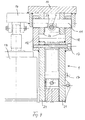
- Fig. 5
- einen Querschnitt durch den Bügel an der Stelle der Federanlenkung.
- Fig. 1
- 3 shows a section along the line A - B in FIG. 2,
- Fig. 2
- a side view of the disc brake,
- Fig. 3
- 1 corresponding view of the brake lever assembly,
- Fig. 4
- a cross-section through the bracket along the line CD in Fig. 1, and
- Fig. 5
- a cross section through the bracket at the location of the spring linkage.
In Fig. 1 und 3 sind mit 1 und 2 einander gegenüberliegende
Bremshebel bezeichnet, die mit den unteren Enden bei 3 bzw. 4
an einer Basis 5 angelenkt sind. Im Mittelbereich der beiden
Bremshebel 1,2 ist über einen Gelenkzapfen jeweils eine Bremsbacke
6 bzw. 6' angelenkt. Der Bremshebel 2 ist am oberen Ende
über einen Gelenkzapfen mit Gelenkachse 8 mit einer Spindel 7
verbunden, die über einen Gelenkzapfen mit Anlenkachse 9 mit
einem Bügel 10 verbunden ist, an dem über einen Gelenkzapfen
mit Gelenkachse 11 das obere Ende des Bremshebels 1 angelenkt
ist.1 and 3 are 1 and 2 opposite to each other
Brake lever designated, with the lower ends at 3 and 4 respectively
are hinged to a
Bei der Ausführungsform nach den Fig. 1 und 3 übergreift der
Bügel 10 die beiden oberen Enden der Bremshebel 1,2, wobei am
in Fig. 1 linken, freien Ende des Bügels 10 ein Federpaket 12
angreift, dessen anderes Ende mit der Basis 5 verbunden ist.
Dieses Federpaket 12 wirkt in Schließrichtung der Bremse, d.h.
der Bügel 10 wird durch das Federpaket 12 in die in Fig. 1
wiedergegebene Schließstellung nach unten gezogen. Auf der
gegenüberliegenden Seite ist ein weiteres Federpaket 12' zwischen
Basis 5 und Bügel 10 angeordnet, das ebenfalls in
Schließrichtung wirkt und das rechte Ende des Bügels 10 nach
oben drückt.In the embodiment according to FIGS. 1 and 3, the
Bracket 10, the two upper ends of the
Wie Fig. 2 zeigt, ist an der Basis 5 ein elektrohydraulisches
Gerät 13 angelenkt, das an einem seitlichen Ansatz 14 des
Bügels 10 gelenkig angreift und mittels dem der Bügel 10 aus
der dargestellten Schließstellung, in der die Bremsbacken 6,
6' an der in Fig. 2 angedeuteten Bremsscheibe 15 anliegen, in
die Öffnungsstellung nach oben verschwenkt wird, in der die
beiden oberen Enden der Bremshebel 1,2 voneinander weg bewegt
werden. Die Anlenkachse 9 der Spindel 7 am Bügel 10 liegt in
der Ansicht nach Fig. 1 und 3 in einem Abstand auf der Außenseite
des Gelenkzapfens mit der Gelenkachse 11 zwischen
Bremshebel 1 und Bügel 10. Wenn der Bügel 10 aus der in Fig. 1
wiedergegebenen Stellung im Uhrzeigersinn durch das elektrohydraulische
Lüftgerät 13, das etwa an der Stelle der Gelenkachse
8 am Bügel 10 angreift, nach oben verschwenkt wird, wandert
die Anlenkachse 9 der Spindel 7 relativ zur Gelenkachse 11
nach unten und innen, wobei über die Spindel 7 gleichzeitig
der Abstand zwischen den Gelenkachsen 8 und 11 vergrößert
wird, so daß sich die Bremsbacken 6,6' von der Bremsscheibe 15
lösen. Die Lüft- bzw. Offenstellung der Bremse ist in Fig. 3
durch gestrichelte Linien wiedergegeben. Durch Verschwenken
des Bügels 10 in die Offenstellung wandert die Gelenkachse 11
zusammen mit der Anlenkachse 9 etwas nach außen, wie Fig. 3
zeigt, während gleichzeitig die Anlenkachse 9 nach unten und
innen bewegt wird.As shown in FIG. 2, there is an electrohydraulic at the
Bei einer praktischen Ausführungsform bildet die Verbindungslinie
zwischen den Achsen 9 und 11 einen Winkel von etwa
4 bis 8° mit der Verbindungslinie zwischen den Gelenkachsen 8
und 11 in der in Fig. 1 wiedergegebenen Schließstellung der
Bremse. Der horizontale Abstand zwischen den Achsen 9 und 11
kann bei etwa 60mm liegen. In a practical embodiment, the connecting line forms
an angle of approximately between the
Der Gelenkzapfen mit der Anlenkachse 9 wirkt bei dieser Anordnung
relativ zum Gelenkzapfen mit der Achse 11 als Exzenter,
wobei durch Verschwenken des Bügels 10 aus der Offenstellung
nach unten in die Schließstellung der wirksame Hebel vergrößert
wird. Hierdurch können erheblich höhere Bremskräfte angelegt
werden als bei der bekannten Ausführungsform, bei der die
Anlenkachse 9 auf der Innenseite der Gelenkachse 11, also innerhalb
des Abstandes zwischen den Gelenkachsen 8 und 11
liegt. Bei der Anordnung nach den Fig. 1 und 3 ergibt sich
beim Schließen der Bremse ein Hebelverhältnis von 1:30 bis
1:34, während sich beim öffnen ein Hebelverhältnis von etwa
1:16 ergibt. Insgesamt kann durch die beschriebene Anordnung
die Bremskraft gegenüber der bekannten Bauform nahezu verdoppelt
werden.The hinge pin with the
Beim Lösen der Bremsbacken 6,6' von der Bremsscheibe 15 wird
zwar der wirksame Hebelarm mit fortschreitender Schwenkbewegung
des Bügels 10 nach oben kleiner, hierauf kommt es aber
beim Freigeben der Bremse nicht an.When releasing the
Beim Anlegen der Bremsbacken an der Bremsscheibe werden die
Bremshebel 1 und 2 nur über einen geringen Weg bewegt, beispielsweise
jeweils um 0,337° um die unteren Anlenkstellen 3
und 4 nach innen verschwenkt. Hierbei wird der Bügel 10 aus
der in Fig. 3 gestrichelten Offenstellung um etwa 15,5° nach
unten in die horizontale Stellung verschwenkt, wobei zugleich
die Gelenkachse 11 etwas nach innen wandert, wie durch ausgezogene
Linien in Fig. 3 angegeben.When placing the brake shoes on the brake disc, the
Brake levers 1 and 2 only moved a short way, for example
in each case by 0.337 ° around the
Die beiden Bremshebel 1 und 2 sind an den unteren Enden vorzugsweise
über eine Drehkopplung 16 aneinander abgestützt,
wobei am Bremshebel 1 ein Zylinder beispielsweise angeschweißt
ist, der in eine Nut am gegenüberliegenden Bremshebel 2 eingreift.
Diese Drehkopplung 16 gewährleistet beim Öffnen der
Bremshebel einen gleichmäßigen Lüftspalt zwischen Bremsscheibe
und Bremsbacken. The two brake levers 1 and 2 are preferred at the lower ends
supported against one another via a
Wie die Seitenansicht in Fig. 2 zeigt, ist jeder Bremshebel
durch zwei beabstandete, parallel verlaufende, plattenförmige
Bremshebelteile 21 ausgebildet, die über Verbindungselemente
17 eine Einheit bilden.As the side view in Fig. 2 shows, each brake lever
by two spaced, parallel, plate-shaped
Fig. 4 zeigt einen Schnitt durch die gelenkige Verbindung
zwischen Bremshebel 1 und Bügel 10, der mit zwei beabstandeten
Laschen 20 versehen ist, in denen der Gelenkzapfen mit der
Gelenkachse 11 befestigt ist. Auf den Außenseiten der beiden
Bremshebelteile 21 des Bremshebels 1 sind Verlängerungsteile
18 angeschweißt, in denen die an den Laschen 20 nach außen
vorstehenden Enden des Gelenkzapfens drehbar gelagert sind.
Der Gelenkzapfen selbst ist, wie Fig. 4 zeigt, mit einer Ausnehmung
23 versehen, durch die die Spindel 7 verläuft, die in
der Ansicht nach Fig. 1 durch den Querschnitt des Gelenkzapfens
mit der Gelenkachse 11 verläuft.Fig. 4 shows a section through the articulated connection
between
An der Spindel 7 kann eine in Fig. 1 bei 19 dargestellte Gestängenachstellvorrichtung
angebracht sein, die bei Verschleiß
des Bremsbelages der Bremsbacken automatisch den vorgegebenen
Lüftspalt nachjustiert.On the
Die Federpakete 12 und 12' werden vorzugsweise in der Mitte
zwischen den beiden Bremshebelteilen bzw. in der Ebene der
Bremshebel 1 und 2 angeordnet, wie Fig. 2 und 5 zeigen. Durch
den symmetrischen Kraftangriff tritt weniger Reibung beim
Schließen der Bremse durch die Federpakete auf, weil gegenüber
der bekannten Bauform durch den Federangriff kein Moment quer
zu den Bremshebeln erzeugt wird.The
Fig. 5 zeigt die Anlenkung des Federpakets 12 auf der Seite
des Bremshebels 2. Das zwischen den Bremshebelteilen 21 auf
der Mittelachse angeordnete Federpaket 12 ist an einem Gelenkbolzen
24 befestigt, dessen Enden in Laschen des Bügels 10
gelagert sind. Der Bügel 10 ist hierbei U-förmig gestaltet, so
daß die gesamte Oberseite der Bremse durch den Bügel 10 abgedeckt
wird. Fig. 5 shows the articulation of the
Durch die erfindungsgemäße Anordnung der Anlenkachse 9 relativ
zu den Gelenkachsen 8 und 11 erhält man neben einer hohen
Bremskraft auch einen ausreichend langen Weg der Bremsbacken.
Bei einem Gesamthub des elektrohydraulischen Lüftgerätes 13
von 60mm werden etwa 50mm zum Lüften der Bremse verwendet,
wobei sich ein Lüftspalt von 1,7mm an jeder Bremsbacke ergibt,
insgesamt also 3,4mm Lüftweg. Der Resthub des Lüftgerätes von
10mm wird als Reservehub zum Ausgleich von Änderungen der Bremsbackenstärke
und dgl. verwendet.Due to the arrangement of the
Claims (6)
dadurch gekennzeichnet,
daß die Anlenkachse (9) der Spindel (7) am Bügel (10) auf der Außenseite der Gelenkachse (11) zwischen Bügel (10) und Bremshebel (1) angeordnet ist.Disc brake with two opposing brake levers (1, 2) carrying brake shoes (6), which are pivotally supported at one end and connected to one another at the other end by a spindle (7), which have one end on a brake lever (2) and the the other end is articulated to a bracket (10) with which the other brake lever (1) is articulated at a distance from the articulation axis (9) of the spindle (7), the bracket (10) being actuated by an actuating device (12, 13 ) can be swiveled to open and close the brake,
characterized,
that the articulation axis (9) of the spindle (7) on the bracket (10) on the outside of the hinge axis (11) between the bracket (10) and brake lever (1) is arranged.
wobei die Anlenkachse (9) der Spindel (7) am Bügel (10) unterhalb der Verbindungslinie zwischen den Gelenkachsen ( 8, 11) der Bremshebel (1,2) liegt.Disc brake according to claim 1,
the articulation axis (9) of the spindle (7) on the bracket (10) below the connecting line between the articulation axes (8, 11) of the brake levers (1, 2).
wobei die Verbindungslinie zwischen der Gelenkachse (11) des Bremshebels (1) und der Anlenkachse (9) der Spindel (7) einen Winkel von etwa 4 bis 8° mit der Verbindungslinie zwischen der Gelenkachse ( 8) des einen Bremshebels (2) und der Gelenkachse (11) des mit dem Bügel (10) verbundenen Bremshebels (1) in der Schließstellung der Bremse bildet.Disc brake according to claim 2,
wherein the connecting line between the hinge axis (11) of the brake lever (1) and the articulation axis (9) of the spindle (7) forms an angle of approximately 4 to 8 ° with the connecting line between the hinge axis (8) of the one brake lever (2) and the Hinge axis (11) of the brake lever (1) connected to the bracket (10) forms in the closed position of the brake.
wobei der Bügel (10) die beiden Enden der Bremshebel (1,2) übergreift und wenigstens auf einer Seite mit einem Federpaket (12) gelenkig verbunden ist. Disc brake according to one of the preceding claims,
wherein the bracket (10) overlaps the two ends of the brake levers (1, 2) and is articulated at least on one side with a spring assembly (12).
wobei das bzw. die Federpakete (12) im wesentlichen in der Ebene der beiden Bremshebel (1,2) angeordnet ist bzw. sind.Disc brake according to claim 4,
wherein the spring assembly (s) (12) is or are arranged essentially in the plane of the two brake levers (1, 2).
wobei die beiden Bremshebel (1,2) an den unteren Enden über eine Drehkopplung (16) aneinander abgestützt sind.Disc brake according to one of the preceding claims,
the two brake levers (1, 2) being supported on one another at the lower ends via a rotary coupling (16).
Applications Claiming Priority (2)
| Application Number | Priority Date | Filing Date | Title |
|---|---|---|---|
| DE19735127 | 1997-08-13 | ||
| DE19735127A DE19735127C1 (en) | 1997-08-13 | 1997-08-13 | Disc brake |
Publications (2)
| Publication Number | Publication Date |
|---|---|
| EP0897071A2 true EP0897071A2 (en) | 1999-02-17 |
| EP0897071A3 EP0897071A3 (en) | 2001-09-19 |
Family
ID=7838885
Family Applications (1)
| Application Number | Title | Priority Date | Filing Date |
|---|---|---|---|
| EP98115171A Withdrawn EP0897071A3 (en) | 1997-08-13 | 1998-08-12 | Disc brake |
Country Status (2)
| Country | Link |
|---|---|
| EP (1) | EP0897071A3 (en) |
| DE (1) | DE19735127C1 (en) |
Cited By (1)
| Publication number | Priority date | Publication date | Assignee | Title |
|---|---|---|---|---|
| FR2826417A1 (en) * | 2001-06-20 | 2002-12-27 | Sime Stromag Sas | DISC BRAKE ESPECIALLY FOR INDUSTRIAL USE |
Families Citing this family (4)
| Publication number | Priority date | Publication date | Assignee | Title |
|---|---|---|---|---|
| DE102012107723B4 (en) | 2012-08-22 | 2019-04-18 | Sibre Siegerland-Bremsen Gmbh | Fail-safe device, in particular brake unit for a disc brake |
| DE102013114525A1 (en) * | 2013-12-19 | 2015-06-25 | Pintsch Bubenzer Gmbh | Stop arrangement and braking device with such |
| BR102020008271A2 (en) * | 2020-04-24 | 2021-11-09 | Vulkan Do Brasil Ltda | ELECTRO-HYDRAULIC DISC BRAKE |
| BR102020008272A2 (en) * | 2020-04-24 | 2021-11-09 | Vulkan Do Brasil Ltda | ELECTRO-HYDRAULIC DISC BRAKE |
Family Cites Families (6)
| Publication number | Priority date | Publication date | Assignee | Title |
|---|---|---|---|---|
| DE1822016U (en) * | 1959-10-07 | 1960-11-17 | Alfred Tevess Maschinen Und Ar | HAND BRAKE DEVICE FOR A DISC BRAKE. |
| DE1855340U (en) * | 1960-09-07 | 1962-07-19 | Ruote Amadori Collettiva Di Am | MANUAL DISC BRAKE FOR MOTOR VEHICLES. |
| FR1398074A (en) * | 1964-03-25 | 1965-05-07 | Backlash compensation device for braking rotating parts, such as shafts, pulleys and the like | |
| DE4024025C2 (en) * | 1990-07-28 | 1995-04-27 | Asku Scholten Gmbh | Part-pad disc brake |
| JPH08159179A (en) * | 1994-12-05 | 1996-06-18 | Toyo Umpanki Co Ltd | Disc brake device for vertical reach forklift |
| JPH1137186A (en) * | 1997-07-23 | 1999-02-09 | Nippon Aikiyan Kk | Disk braking device |
-
1997
- 1997-08-13 DE DE19735127A patent/DE19735127C1/en not_active Expired - Fee Related
-
1998
- 1998-08-12 EP EP98115171A patent/EP0897071A3/en not_active Withdrawn
Non-Patent Citations (1)
| Title |
|---|
| None |
Cited By (2)
| Publication number | Priority date | Publication date | Assignee | Title |
|---|---|---|---|---|
| FR2826417A1 (en) * | 2001-06-20 | 2002-12-27 | Sime Stromag Sas | DISC BRAKE ESPECIALLY FOR INDUSTRIAL USE |
| EP1270980A1 (en) * | 2001-06-20 | 2003-01-02 | Sime-Stromag SA | Disc brake, in particular for industrial use |
Also Published As
| Publication number | Publication date |
|---|---|
| DE19735127C1 (en) | 1999-03-11 |
| EP0897071A3 (en) | 2001-09-19 |
Similar Documents
| Publication | Publication Date | Title |
|---|---|---|
| DE3610789C2 (en) | ||
| EP0520343A1 (en) | Installation for opening and closing of a vehicle hood | |
| DE868963C (en) | Locking device for the pendulum axles of crane vehicles | |
| EP0443050B1 (en) | Assembly for the operation of a damper door | |
| EP0897071A2 (en) | Disc brake | |
| EP2823193B1 (en) | Brake unit for a vehicle and vehicle having a brake unit of said type | |
| DE3148982C2 (en) | Hydraulically operated device on grippers for damping oscillating movements of the gripper frame | |
| DE1575756A1 (en) | Disc brake | |
| EP0208115A1 (en) | Gear-shifting device for a hydrostatic transmission, particularly for motor vehicles | |
| EP0349817B1 (en) | Independent wheel arrangement for railway vehicles | |
| DE3707700A1 (en) | Multi-axle steering system | |
| DE4126600C2 (en) | Transport gripper with locking device | |
| DE19833445B4 (en) | Disc brake for rail vehicles | |
| DE1920593U (en) | DISC BRAKE, IN PARTICULAR FOR HYDRAULIC BRAKE SYSTEMS. | |
| DE2839416C2 (en) | ||
| DE19959940B4 (en) | load carrier foot | |
| DE102015108638B3 (en) | Actuation device of a disc brake | |
| DE1455978A1 (en) | Disc brake set as an additional device in addition to a hydraulically operated disc brake set | |
| DE19512384C2 (en) | Middle buffer coupling for rail vehicles | |
| DE4040016A1 (en) | Disc brake pads supported on two pivoting brake levers - has levers held against wedge by expansion element, wedge transmitting brake force | |
| EP0665334A2 (en) | Milling machine and articulation | |
| DE1800595A1 (en) | Disc brake device, in particular for rail vehicles | |
| DE2208251C3 (en) | Disc brake for rail vehicles | |
| DE625838C (en) | Device for adapting the braking force to the vehicle load in the case of vehicle brakes | |
| DE4236696A1 (en) | Swing motion damper for container crane load - has load support traverse of four-link frame, displaceable in swing direction |
Legal Events
| Date | Code | Title | Description |
|---|---|---|---|
| PUAI | Public reference made under article 153(3) epc to a published international application that has entered the european phase |
Free format text: ORIGINAL CODE: 0009012 |
|
| AK | Designated contracting states |
Kind code of ref document: A2 Designated state(s): AT BE CH CY DE DK ES FI FR GB GR IE IT LI LU MC NL PT SE |
|
| AX | Request for extension of the european patent |
Free format text: AL;LT;LV;MK;RO;SI |
|
| PUAL | Search report despatched |
Free format text: ORIGINAL CODE: 0009013 |
|
| AK | Designated contracting states |
Kind code of ref document: A3 Designated state(s): AT BE CH CY DE DK ES FI FR GB GR IE IT LI LU MC NL PT SE |
|
| AX | Request for extension of the european patent |
Free format text: AL;LT;LV;MK;RO;SI |
|
| AKX | Designation fees paid | ||
| REG | Reference to a national code |
Ref country code: DE Ref legal event code: 8566 |
|
| STAA | Information on the status of an ep patent application or granted ep patent |
Free format text: STATUS: THE APPLICATION IS DEEMED TO BE WITHDRAWN |
|
| 18D | Application deemed to be withdrawn |
Effective date: 20020320 |