EP0896155A2 - Compresseur à capacité variable dont le réglage de la capacité est amélioré en phase initiale de son démarrage - Google Patents
Compresseur à capacité variable dont le réglage de la capacité est amélioré en phase initiale de son démarrage Download PDFInfo
- Publication number
- EP0896155A2 EP0896155A2 EP98114928A EP98114928A EP0896155A2 EP 0896155 A2 EP0896155 A2 EP 0896155A2 EP 98114928 A EP98114928 A EP 98114928A EP 98114928 A EP98114928 A EP 98114928A EP 0896155 A2 EP0896155 A2 EP 0896155A2
- Authority
- EP
- European Patent Office
- Prior art keywords
- suction
- chamber
- passage
- compressor
- valve
- Prior art date
- Legal status (The legal status is an assumption and is not a legal conclusion. Google has not performed a legal analysis and makes no representation as to the accuracy of the status listed.)
- Ceased
Links
Images

Classifications
-
- F—MECHANICAL ENGINEERING; LIGHTING; HEATING; WEAPONS; BLASTING
- F04—POSITIVE - DISPLACEMENT MACHINES FOR LIQUIDS; PUMPS FOR LIQUIDS OR ELASTIC FLUIDS
- F04B—POSITIVE-DISPLACEMENT MACHINES FOR LIQUIDS; PUMPS
- F04B27/00—Multi-cylinder pumps specially adapted for elastic fluids and characterised by number or arrangement of cylinders
- F04B27/08—Multi-cylinder pumps specially adapted for elastic fluids and characterised by number or arrangement of cylinders having cylinders coaxial with, or parallel or inclined to, main shaft axis
- F04B27/14—Control
- F04B27/16—Control of pumps with stationary cylinders
- F04B27/18—Control of pumps with stationary cylinders by varying the relative positions of a swash plate and a cylinder block
- F04B27/1804—Controlled by crankcase pressure
- F04B2027/1822—Valve-controlled fluid connection
- F04B2027/1831—Valve-controlled fluid connection between crankcase and suction chamber
-
- F—MECHANICAL ENGINEERING; LIGHTING; HEATING; WEAPONS; BLASTING
- F04—POSITIVE - DISPLACEMENT MACHINES FOR LIQUIDS; PUMPS FOR LIQUIDS OR ELASTIC FLUIDS
- F04B—POSITIVE-DISPLACEMENT MACHINES FOR LIQUIDS; PUMPS
- F04B27/00—Multi-cylinder pumps specially adapted for elastic fluids and characterised by number or arrangement of cylinders
- F04B27/08—Multi-cylinder pumps specially adapted for elastic fluids and characterised by number or arrangement of cylinders having cylinders coaxial with, or parallel or inclined to, main shaft axis
- F04B27/14—Control
- F04B27/16—Control of pumps with stationary cylinders
- F04B27/18—Control of pumps with stationary cylinders by varying the relative positions of a swash plate and a cylinder block
- F04B27/1804—Controlled by crankcase pressure
- F04B2027/1886—Open (not controlling) fluid passage
- F04B2027/1895—Open (not controlling) fluid passage between crankcase and suction chamber
Definitions
- the present invention relates to a variable displacement compressor for use in, for example, compressing a refrigerant gas in a vehicle air conditioner or the like.
- variable displacement compressor of this type is described in, for example, Japanese Second (examined) Patent Publication No. 4-74549.
- the variable displacement compressor is provided with a suction chamber, a crank chamber and a discharge chamber and controls a displacement thereof depending on a pressure differential between the crank chamber and the suction chamber.
- the compressor is provided with a particular passage which is for allowing the flow of gas from the crank chamber into the suction chamber and will be called hereinafter a bleed passage.
- the bleed passage even being small, is always opened.
- the crank chamber and the suction chamber always communicate with each other.
- both chambers always communicate with each other, assuming that the compressor is stopped for hours and a temperature in a vehicle compartment is relatively high while a temperature around the compressor is relatively low, a phenomenon occurs that a large amount of liquid refrigerant in a low pressure side circuit flows into the crank chamber. If the compressor is started in this state, it is difficult for the liquid refrigerant to escape from the crank chamber so that the pressure differential between the crank chamber and the suction chamber is out of control to be increased. As a result, until the liquid refrigerant is removed from the crank chamber, the compressor continues to be operated with the minimum displacement so that the cooling power becomes insufficient.
- a variable displacement compressor comprising a suction chamber, a crank chamber, and a discharge chamber and having a displacement controlled dependent on a pressure-difference which is between the crank chamber and the suction chamber.
- the compressor further comprises a bleed passage establishing communication between the suction chamber and the crank chamber and bleed control means connected to the bleed passage for fully closing the bleed passage while the compressor is stopped.
- a variable displacement compressor comprising a suction chamber having a suction pressure, a crank chamber having a crank pressure, a discharge chamber having a discharge pressure, and displacement control means for controlling a displacement of the compressor in dependence on a differential pressure which is between the crank pressure and the suction pressure.
- the displacement control means comprises a bleed passage establishing communication between the suction chamber and the crank chamber and a bleed control mechanism which fully closes the bleed passage while the compressor is stopped.
- a variable displacement compressor comprising a cylinder block having a plurality of cylinder bores around a central axis extending in a predetermined direction, a plurality of pistons inserted in the cylinder bores, respectively, to be movable in the predetermined direction, a rear housing placed at one end of the cylinder block in the predetermined direction and forming a suction chamber and a discharge chamber, a valve plate placed between the cylinder block and the rear housing, a suction valve placed between the cylinder block and the valve plate for controlling communication between each of the cylinders and each of the suction chamber and the discharge chamber, a front housing placed at another end of the cylinder block in the predetermined direction and forming a crank chamber, a drive shaft extending in the predetermined direction and rotated around the central axis, a crank mechanism connected to the drive shaft and the pistons in the crank chamber for moving the pistons in dependence on the rotation of the drive shaft, a bleed passage establishing communication between the suction chamber
- variable displacement compressor according to a preferred embodiment of the present invention will be described hereinbelow.
- the variable displacement compressor is of a wobble plate type known in the art.
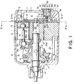
- variable displacement compressor is for use in, for example, compressing a refrigerant gas in a vehicle air conditioner, and includes a cylinder block 1. On the right side of the cylinder block 1, a rear housing 3 is provided via a valve plate 2 interposed therebetween so as to form a suction chamber 4 and a discharge chamber 6. The suction chamber 4 is connected to a suction port 5, while the discharge chamber 6 is connected to a discharge port 7.
- a front housing 8 On the left side of the cylinder block 1, a front housing 8 is provided so as to form a crank chamber 9.
- a drive shaft 10 passes through the crank chamber 9 and extends along a central axis of the cylinder block 1 in a predetermined direction.
- the drive shaft 10 is rotatably supported on the cylinder block 1 and the front housing 8 via bearings 11.
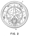
- the cylinder block 1 is provided with a plurality of (five in this embodiment) cylinder bores 12 arranged at regular intervals in a circumferential direction of the cylinder block 1 around the central axis of the cylinder block 1.
- a piston 13 is received in each of the cylinder bores 12, and a piston rod 14 is connected to each of the pistons 13.
- a suction valve 15 and a discharge valve mechanism 16 are attached to the valve plate 2 and engaged therewith in a rotation direction.
- a swash plate 19a is coupled to the rotor 17 via a coupling pin 18 so as to be variable in inclination.
- a wobble plate 19b is provided so as to confront the swash plate 19a.
- a guide rod 20 is further provided between the cylinder block 1 and the front housing 8. The wobble plate 19b is engaged with the guide rod 20 in a rotation direction, and thus it rocks without rotation due to the known principle.
- the foregoing piston rods 14 are connected to a peripheral portion of the wobble plate 19b.
- a combination of the rotor 17, the swash plate 19a, and the wobble plate 19b will be referred to as a crank mechanism.
- the wobble plate 19b wobbles to cause the pistons 13 to make reciprocating motions in the corresponding cylinder bores 12.
- the refrigerant gas is sucked into the suction chamber 4 via the suction port 5 and further sucked into the cylinder bores 12 via the suction valve 15 which controls the opening of suction holes of the valve plate 2 synchronously with a compressing operation of the compressor. Then, the refrigerant gas is compressed in the cylinder bores 12, introduced into the discharge chamber 6 via the discharge valve mechanism 16 and then discharged through the discharge port 7.
- the rear housing 3 is formed with a swell portion 21 swelling toward the discharge chamber 6.
- An induction passage 22 is provided for establishing communication between the crank chamber 9 and the discharge chamber 6 via the cylinder block 1, the valve plate 2 and the swell portion 21.
- the induction passage 22 extends through a passage 23, a passage 24, a passage 26, a bearing bore 25, the bearing 11 and a passage 27.
- an induction passage open/close valve 28 is provided between the passages 23 and 24 and will be referred to as a passage valve.
- the induction passage open/close valve 28 comprises a valve seat 29, a ball 30 confronting the valve seat 29, and a compression spring 31 biasing the ball 30 toward the valve seat 29.
- the swell portion 21 is formed with a recess 32 in which a bellows 33 is disposed using a mounting ring 34 with an O-ring 35 interposed between the mounting ring 34 and an inner periphery of the recess 32, and further retained by a snap ring 36.
- the bellows 33 has at its tip a mounting plate 37 which holds the ball 30 via a rod 38.
- an induction control mechanism 39 is provided for adjusting the pressure in the crank chamber 9.
- a combination of the compression spring 31 and the bellows 33 will be referred to as a valve driving arrangement.
- a spring support 40 is fixed to the mounting ring 34 and receives thereon a spring 41 applying an extending force to the bellows 33.
- the inside 42 of the bellows 33 is under vacuum, and a pressure sensitive chamber 44 is defined around the bellows 33.
- the pressure sensitive chamber 44 communicates with the suction chamber 4 via a passage 47.
- a bleed passage 46 is provided for establishing communication between the suction chamber 4 and the crank chamber 9.
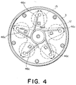
- the bleed passage 46 has a through hole 46a extending through the cylinder block 1 and the suction valve 15 in an axial direction, an annular groove 46b formed on a surface of the valve plate 2 confronting the cylinder block 1 so as to communicate with the through hole 46a, and five extension grooves 46c formed on the foregoing surface of the valve plate 2 and extending outward from the annular groove 46b to positions corresponding to the respective five cylinder bores 12 while confronting the suction valve 15.
- the refrigerant gas flows as bow-by gas from the cylinder bores 12 into the crank chamber 9 as well known in the art.
- the pressure in the suction chamber 4 is not less than a set value, the bellows 33 and the spring 41 contract so that the ball 30 abuts the valve seat 29 under pressure to block the induction passage 22.
- the blow-by gas returns from the crank chamber 9 to the cylinder bores 12 through the bleed passage 46. Therefore, the pressure in the crank chamber 9 becomes relatively lower so that the inclination of the swash plate 19a varies to increase the discharge capacity.
- the suction valve 15 When the variable displacement compressor is stopped, the suction valve 15 fully closes the bleed passage 46 so that the communication between the crank chamber 9 and the suction chamber 4 is disabled. In this event, the suction valve 15 serves as a bleed control arrangement or mechanism. Therefore, when the temperature in the vehicle compartment is high while the temperature around the compressor is low after the compressor has been stopped for hours, the liquid refrigerant in the low pressure side circuit is prevented from flowing into the crank chamber 9 so that the shift to the maximum displacement can be smoothly carried out at the initial stage of the start-up. In this case, the suction valve 15 constitutes a bleed control mechanism.
- variable displacement compressor since the bleed passage 46 is closed while the compressor is stopped, the liquid refrigerant is prevented from flowing into the crank chamber 9 so that the shift to the maximum displacement can be smoothly carried out at the initial stage of the start-up.
- the present invention has thus far been described in conjunction with the single preferred embodiment thereof, it will readily be possible for those skilled in the art to put this invention into practice in various other manners.
- the present invention is applicable to a variable displacement compressor of a single swash plate type known in the art.
Applications Claiming Priority (3)
| Application Number | Priority Date | Filing Date | Title |
|---|---|---|---|
| JP9214515A JPH1162823A (ja) | 1997-08-08 | 1997-08-08 | 可変容量圧縮機 |
| JP21451597 | 1997-08-08 | ||
| JP214515/97 | 1997-08-08 |
Publications (2)
| Publication Number | Publication Date |
|---|---|
| EP0896155A2 true EP0896155A2 (fr) | 1999-02-10 |
| EP0896155A3 EP0896155A3 (fr) | 1999-09-15 |
Family
ID=16657007
Family Applications (1)
| Application Number | Title | Priority Date | Filing Date |
|---|---|---|---|
| EP98114928A Ceased EP0896155A3 (fr) | 1997-08-08 | 1998-08-07 | Compresseur à capacité variable dont le réglage de la capacité est amélioré en phase initiale de son démarrage |
Country Status (3)
| Country | Link |
|---|---|
| US (1) | US6129519A (fr) |
| EP (1) | EP0896155A3 (fr) |
| JP (1) | JPH1162823A (fr) |
Cited By (2)
| Publication number | Priority date | Publication date | Assignee | Title |
|---|---|---|---|---|
| FR2809459A1 (fr) * | 2000-05-24 | 2001-11-30 | Sanden Corp | Compresseur a cylindree variable du type a came inclinee avec un mecanisme de commande de capacite |
| EP1283360A2 (fr) * | 2001-08-10 | 2003-02-12 | Kabushiki Kaisha Toyota Jidoshokki | Structure de conduit pour compresseur à capacité variable |
Families Citing this family (10)
| Publication number | Priority date | Publication date | Assignee | Title |
|---|---|---|---|---|
| JP2000199479A (ja) | 1998-10-30 | 2000-07-18 | Toyota Autom Loom Works Ltd | 可変容量型圧縮機 |
| KR20020000966A (ko) * | 2000-06-23 | 2002-01-09 | 신영주 | 사판식 압축기의 실린더부 흡입공 구조 |
| JP4031945B2 (ja) * | 2002-04-09 | 2008-01-09 | サンデン株式会社 | 可変容量圧縮機の容量制御弁 |
| US6939112B2 (en) | 2002-04-25 | 2005-09-06 | Sanden Corporation | Variable displacement compressors |
| DE10320115A1 (de) * | 2002-05-08 | 2003-11-27 | Sanden Corp | Kompressor |
| US7645125B2 (en) * | 2004-06-22 | 2010-01-12 | Delphi Technologies, Inc. | Refrigerant compressor with improved oil retention |
| JP2007138785A (ja) * | 2005-11-16 | 2007-06-07 | Toyota Industries Corp | 車両用冷凍回路の制御装置、容量可変型圧縮機及び容量可変型圧縮機用制御弁 |
| JP5065120B2 (ja) * | 2008-03-28 | 2012-10-31 | サンデン株式会社 | 往復動圧縮機 |
| CN106870331A (zh) * | 2015-12-11 | 2017-06-20 | 浙江三花汽车零部件有限公司 | 一种用于变排量压缩机的控制阀及其阀体的加工方法 |
| JP6991107B2 (ja) * | 2018-06-29 | 2022-01-12 | サンデン・オートモーティブコンポーネント株式会社 | 可変容量圧縮機 |
Citations (1)
| Publication number | Priority date | Publication date | Assignee | Title |
|---|---|---|---|---|
| JPH0474549A (ja) | 1990-07-16 | 1992-03-09 | Iwata Air Compressor Mfg Co Ltd | 2液混合スプレーガン |
Family Cites Families (23)
| Publication number | Priority date | Publication date | Assignee | Title |
|---|---|---|---|---|
| US4428718A (en) * | 1982-02-25 | 1984-01-31 | General Motors Corporation | Variable displacement compressor control valve arrangement |
| JPS60135680A (ja) * | 1983-12-23 | 1985-07-19 | Sanden Corp | 揺動式圧縮機 |
| JPS6287679A (ja) * | 1985-10-11 | 1987-04-22 | Sanden Corp | 容量可変型圧縮機 |
| JP2555026B2 (ja) * | 1986-05-23 | 1996-11-20 | 株式会社日立製作所 | 容量可変型圧縮機 |
| JPS6316177A (ja) * | 1986-07-08 | 1988-01-23 | Sanden Corp | 容量可変型圧縮機 |
| JPS63205469A (ja) * | 1987-02-20 | 1988-08-24 | Sanden Corp | 容量可変型斜板式圧縮機 |
| JPH0649918Y2 (ja) * | 1987-03-24 | 1994-12-14 | サンデン株式会社 | 容量可変型圧縮機 |
| JPS63149319U (fr) * | 1987-03-24 | 1988-09-30 | ||
| JPH01142276A (ja) * | 1987-11-27 | 1989-06-05 | Sanden Corp | 容量可変型斜板式圧縮機 |
| JPH02115577A (ja) * | 1988-10-24 | 1990-04-27 | Sanden Corp | 容量可変形揺動式圧縮機 |
| JPH0343685A (ja) * | 1989-07-05 | 1991-02-25 | Sanden Corp | 容量可変型揺動式圧縮機 |
| DE4033422C2 (de) * | 1990-10-20 | 1999-07-15 | Bosch Gmbh Robert | Taumelscheibenkompressor |
| JP2567549Y2 (ja) * | 1991-07-23 | 1998-04-02 | カルソニック株式会社 | 容量可変斜板式コンプレッサ |
| JP3088536B2 (ja) * | 1991-12-26 | 2000-09-18 | サンデン株式会社 | 可変容量型揺動式圧縮機 |
| JPH05256251A (ja) * | 1992-03-12 | 1993-10-05 | Aisin Seiki Co Ltd | 可変容量圧縮機 |
| JP2572690Y2 (ja) * | 1992-09-02 | 1998-05-25 | サンデン株式会社 | 斜板式圧縮機のピストン回転防止機構 |
| US5486098A (en) * | 1992-12-28 | 1996-01-23 | Kabushiki Kaisha Toyoda Jidoshokki Seisakusho | Swash plate type variable displacement compressor |
| US5577894A (en) * | 1993-11-05 | 1996-11-26 | Kabushiki Kaisha Toyoda Jidoshokki Seisakusho | Piston type variable displacement compressor |
| KR960700411A (ko) * | 1994-03-09 | 1996-01-20 | 이소가이 찌세이 | 가변 압축기(Variable displacement compressor) |
| US5498140A (en) * | 1994-03-16 | 1996-03-12 | Kabushiki Kaisha Toyoda Jidoshokki Seisakusho | Variable displacement compressor |
| US5624240A (en) * | 1994-06-27 | 1997-04-29 | Kabushiki Kaisha Toyoda Jidoshokki Seisakusho | Piston type variable displacement compressor |
| JP3723283B2 (ja) * | 1996-06-25 | 2005-12-07 | サンデン株式会社 | スクロール型可変容量圧縮機 |
| JPH10238463A (ja) * | 1997-02-25 | 1998-09-08 | Toyota Autom Loom Works Ltd | 圧縮機 |
-
1997
- 1997-08-08 JP JP9214515A patent/JPH1162823A/ja not_active Withdrawn
-
1998
- 1998-07-31 US US09/126,321 patent/US6129519A/en not_active Expired - Fee Related
- 1998-08-07 EP EP98114928A patent/EP0896155A3/fr not_active Ceased
Patent Citations (1)
| Publication number | Priority date | Publication date | Assignee | Title |
|---|---|---|---|---|
| JPH0474549A (ja) | 1990-07-16 | 1992-03-09 | Iwata Air Compressor Mfg Co Ltd | 2液混合スプレーガン |
Cited By (3)
| Publication number | Priority date | Publication date | Assignee | Title |
|---|---|---|---|---|
| FR2809459A1 (fr) * | 2000-05-24 | 2001-11-30 | Sanden Corp | Compresseur a cylindree variable du type a came inclinee avec un mecanisme de commande de capacite |
| EP1283360A2 (fr) * | 2001-08-10 | 2003-02-12 | Kabushiki Kaisha Toyota Jidoshokki | Structure de conduit pour compresseur à capacité variable |
| EP1283360A3 (fr) * | 2001-08-10 | 2004-07-21 | Kabushiki Kaisha Toyota Jidoshokki | Structure de conduit pour compresseur à capacité variable |
Also Published As
| Publication number | Publication date |
|---|---|
| US6129519A (en) | 2000-10-10 |
| EP0896155A3 (fr) | 1999-09-15 |
| JPH1162823A (ja) | 1999-03-05 |
Similar Documents
| Publication | Publication Date | Title |
|---|---|---|
| US4723891A (en) | Variable displacement wobble plate type compressor with improved crankcase pressure control system | |
| US4702677A (en) | Variable displacement wobble plate type compressor with improved wobble angle return system | |
| US5259736A (en) | Swash plate type compressor with swash plate hinge coupling mechanism | |
| CA2095740C (fr) | Compresseur a plateau oscillant et mecanisme de variation de debit | |
| US5531572A (en) | Capacity control valve for a variable capacity refrigerant compressor | |
| US4685866A (en) | Variable displacement wobble plate type compressor with wobble angle control unit | |
| US5032060A (en) | Continuously variable capacity swash plate type refrigerant compressor | |
| EP1059443B1 (fr) | Soupape de contrôle de capacité | |
| US5318410A (en) | Variable displacement compressor | |
| US5137431A (en) | Lubricating mechanism and method for a piston assembly of a slant plate type compressor | |
| EP1081378A2 (fr) | Soupape de régulation d'un compresseur à capacité variable | |
| US5681150A (en) | Piston type variable displacement compressor | |
| EP0318316A1 (fr) | Compresseur à plateau en biais avec mécanisme à déplacement variable | |
| CA1324361C (fr) | Compresseur a piston, a element incline a ressort | |
| US6129519A (en) | Variable displacement compressor in which a displacement control is improved at an initial stage of the start-up thereof | |
| KR19980064124A (ko) | 가변용량 압축기용 제어밸브 | |
| EP0300831B1 (fr) | Compresseur à plateau en biais avec mécanisme à déplacement variable | |
| EP0905376B1 (fr) | Compresseur à capacité variable avec mécanisme de lubrification amélioré | |
| US6572341B2 (en) | Variable displacement type compressor with suction control valve | |
| US6074173A (en) | Variable displacement compressor in which a liquid refrigerant can be prevented from flowing into a crank chamber | |
| JP3293357B2 (ja) | 往復動型圧縮機 | |
| CA2221475C (fr) | Compresseur a cylindree variable | |
| US6192699B1 (en) | Variable capacity compressor | |
| JP2949836B2 (ja) | 斜板式連続可変容量型圧縮機 | |
| US6350106B1 (en) | Variable displacement compressor with capacity control mechanism |
Legal Events
| Date | Code | Title | Description |
|---|---|---|---|
| PUAI | Public reference made under article 153(3) epc to a published international application that has entered the european phase |
Free format text: ORIGINAL CODE: 0009012 |
|
| AK | Designated contracting states |
Kind code of ref document: A2 Designated state(s): DE FR |
|
| AX | Request for extension of the european patent |
Free format text: AL;LT;LV;MK;RO;SI |
|
| PUAL | Search report despatched |
Free format text: ORIGINAL CODE: 0009013 |
|
| AK | Designated contracting states |
Kind code of ref document: A3 Designated state(s): AT BE CH CY DE DK ES FI FR GB GR IE IT LI LU MC NL PT SE |
|
| AX | Request for extension of the european patent |
Free format text: AL;LT;LV;MK;RO;SI |
|
| 17P | Request for examination filed |
Effective date: 20000313 |
|
| AKX | Designation fees paid |
Free format text: DE FR |
|
| 17Q | First examination report despatched |
Effective date: 20000509 |
|
| GRAG | Despatch of communication of intention to grant |
Free format text: ORIGINAL CODE: EPIDOS AGRA |
|
| STAA | Information on the status of an ep patent application or granted ep patent |
Free format text: STATUS: THE APPLICATION HAS BEEN REFUSED |
|
| 18R | Application refused |
Effective date: 20010705 |