EP1283360A2 - Structure de conduit pour compresseur à capacité variable - Google Patents
Structure de conduit pour compresseur à capacité variable Download PDFInfo
- Publication number
- EP1283360A2 EP1283360A2 EP02017854A EP02017854A EP1283360A2 EP 1283360 A2 EP1283360 A2 EP 1283360A2 EP 02017854 A EP02017854 A EP 02017854A EP 02017854 A EP02017854 A EP 02017854A EP 1283360 A2 EP1283360 A2 EP 1283360A2
- Authority
- EP
- European Patent Office
- Prior art keywords
- drive shaft
- chamber
- cylinder block
- bleed passage
- variable displacement
- Prior art date
- Legal status (The legal status is an assumption and is not a legal conclusion. Google has not performed a legal analysis and makes no representation as to the accuracy of the status listed.)
- Withdrawn
Links
- 238000006073 displacement reaction Methods 0.000 title claims abstract description 50
- 239000003507 refrigerant Substances 0.000 claims abstract description 66
- 230000000903 blocking effect Effects 0.000 claims description 39
- 239000000314 lubricant Substances 0.000 claims description 10
- 229920001971 elastomer Polymers 0.000 claims description 7
- 239000005060 rubber Substances 0.000 claims description 7
- 229920000459 Nitrile rubber Polymers 0.000 claims description 3
- -1 polytetrafluoroethylene Polymers 0.000 claims description 3
- 229920001343 polytetrafluoroethylene Polymers 0.000 claims description 3
- 239000004810 polytetrafluoroethylene Substances 0.000 claims description 3
- 229920005989 resin Polymers 0.000 claims 2
- 239000011347 resin Substances 0.000 claims 2
- 238000011144 upstream manufacturing Methods 0.000 claims 2
- 239000012530 fluid Substances 0.000 claims 1
- 230000004308 accommodation Effects 0.000 description 20
- 230000006835 compression Effects 0.000 description 9
- 238000007906 compression Methods 0.000 description 9
- 229920003002 synthetic resin Polymers 0.000 description 6
- 239000000057 synthetic resin Substances 0.000 description 6
- 230000000694 effects Effects 0.000 description 5
- 238000005461 lubrication Methods 0.000 description 5
- 230000005489 elastic deformation Effects 0.000 description 3
- 230000001050 lubricating effect Effects 0.000 description 3
- 238000000465 moulding Methods 0.000 description 3
- 230000003247 decreasing effect Effects 0.000 description 2
- 238000005553 drilling Methods 0.000 description 2
- 230000005611 electricity Effects 0.000 description 2
- 239000000463 material Substances 0.000 description 2
- 230000005540 biological transmission Effects 0.000 description 1
- 230000007423 decrease Effects 0.000 description 1
- 230000005347 demagnetization Effects 0.000 description 1
- 230000006866 deterioration Effects 0.000 description 1
- 238000003754 machining Methods 0.000 description 1
- 230000005415 magnetization Effects 0.000 description 1
- 238000004519 manufacturing process Methods 0.000 description 1
- 238000000926 separation method Methods 0.000 description 1
Images


Classifications
-
- F—MECHANICAL ENGINEERING; LIGHTING; HEATING; WEAPONS; BLASTING
- F04—POSITIVE - DISPLACEMENT MACHINES FOR LIQUIDS; PUMPS FOR LIQUIDS OR ELASTIC FLUIDS
- F04B—POSITIVE-DISPLACEMENT MACHINES FOR LIQUIDS; PUMPS
- F04B27/00—Multi-cylinder pumps specially adapted for elastic fluids and characterised by number or arrangement of cylinders
- F04B27/08—Multi-cylinder pumps specially adapted for elastic fluids and characterised by number or arrangement of cylinders having cylinders coaxial with, or parallel or inclined to, main shaft axis
- F04B27/10—Multi-cylinder pumps specially adapted for elastic fluids and characterised by number or arrangement of cylinders having cylinders coaxial with, or parallel or inclined to, main shaft axis having stationary cylinders
- F04B27/1036—Component parts, details, e.g. sealings, lubrication
- F04B27/109—Lubrication
Definitions
- the present invention relates to a structure of a channel in a variable displacement piston type compressor.
- Japanese Unexamined Patent Publication No. 10-61548 discloses a variable displacement piston type compressor.
- a drive shaft is rotatably supported in a front housing and a cylinder block by a radial bearing.
- Compression reactive force is generated due to the discharge work of a piston.
- the compression reactive force is received by the front housing at its end wall through the piston, a pair of shoes, a swash plate, a lug plate and a thrust bearing.
- the pressure in a crank chamber urges the drive shaft in the direction from the rear side to the front side. Therefore, even when the inclination angle of the swash plate is relatively small, the load acting to the thrust bearing is relatively large.
- the thrust bearing requires lubricating.
- the crank chamber and a suction chamber are connected with each other by an axial passage formed in the drive shaft. Refrigerant in the crank chamber flows into the suction chamber through the axial passage. At this time, lubricant oil that flows with the refrigerant lubricates the thrust bearing.
- the present invention addresses a variable displacement piston type compressor that improves the reliability of a portion requiring lubrication in a crank chamber without increasing the size of the compressor.
- a variable displacement piston type compressor has a housing, a drive shaft, a cam plate and a piston.
- the housing has a cylinder block including a plurality of cylinder bores.
- the housing defines a crank chamber, a suction pressure region and a discharge pressure region.
- the suction pressure region includes a suction chamber.
- the discharge pressure region includes a discharge chamber.
- the drive shaft is rotatably supported by the housing.
- the drive shaft has a first end and a second end. The first end of the drive shaft extends through the housing.
- the cylinder block is placed between the first end and the second end.
- the suction chamber and the discharge chamber are defined near the first end relative to the cylinder block.
- the crank chamber is defined near the second end relative to the cylinder block.
- the cam plate is inclinably supported by the drive shaft in the crank chamber.
- the cam plate is integrally rotated with the drive shaft.
- the piston is accommodated in each cylinder bore.
- the rotation of the cam plate is converted into the reciprocating movement of the piston in accordance with the inclination angle of the cam plate.
- Refrigerant in the suction chamber is drawn into the cylinder bores due to the suction work of the piston.
- the refrigerant in the cylinder bores is discharged into the discharge chamber due to the discharge work of the piston.
- Refrigerant in the discharge pressure region is supplied into the crank chamber and the refrigerant in the crank chamber is bled into the suction pressure region through a bleed passage for controlling pressure in the crank chamber. Thereby, the inclination angle of the cam plate is controlled.
- the crank chamber and the suction chamber are connected with each other through the bleed passage.
- the bleed passage is formed outside of the drive shaft.
- a variable displacement piston type compressor has a cylinder block, a piston, a cam plate, a crank chamber, a drive shaft, a suction chamber and a discharge chamber.
- the cylinder block includes a plurality of cylinder bores.
- the piston functions so as to compress refrigerant in each cylinder bore.
- the cam plate is movably connected to the piston for reciprocating the piston.
- the crank chamber is defined near one end of the cylinder block.
- the drive shaft has a rotational axis for rotating to drive the cam plate. The drive shaft is urged in a direction of the rotational axis while the piston reciprocates.
- the suction chamber is defined near the opposite end to the crank chamber relative to the cylinder block.
- the refrigerant in the suction chamber is drawn into the cylinder bores due to the suction work of the piston.
- the discharge chamber is defined near the opposite end to the crank chamber relative to the cylinder block.
- the refrigerant in each cylinder bore is discharged to the discharge chamber due to the discharge work of the piston.
- the refrigerant in the discharge chamber is supplied into the crank chamber and the refrigerant in the crank chamber is bled into the suction chamber through a bleed passage for controlling pressure in the crank chamber.
- the bleed passage is formed outside of the drive shaft.
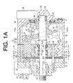
- FIG. 1A A first preferred embodiment according to the present invention in a variable displacement piston type compressor will now be described with reference to FIGs. 1A through 5.
- FIG. 1A the left side and the right side of the drawing respectively correspond to the front side and the rear side of the compressor.
- a front housing 11 and a rear housing 12 constitute a compressor housing 10.
- An end surface of a circumferential wall 34 of the front housing 11 and an end surface of a circumferential wall 35 of the rear housing 12 are secured to each other through a gasket 36.
- the front housing 11 and the rear housing 12 are fixed to each other by a plurality of bolts 37.
- a valve port plate 20, a suction valve plate 21, a discharge valve plate 22 and a retainer plate 23 are fitted in the front housing 11.
- a suction chamber 111 and a discharge chamber 112 are defined between the valve port plate 20 and an end wall 32 of the front housing 11.
- the suction chamber 111 is separated from the discharge chamber 112 by a separation wall 33 and is surrounded by the discharge chamber 112.
- the reference numerals in FIG. 4 are applied to substantially the same components in FIG. 1A, and the corresponding description will be provided later with respect to FIG. 1A if it has not yet been provided. If the description has been previously given, it will not be reiterated.
- a cylinder block 19 is fitted in the front housing 11 so as to secure the suction valve plate 21.
- the end wall 32 of the front housing 11 is screwed by a plurality of screws 38 through the cylinder block 19.
- the cylinder block 19 is fixed to the front housing 11.
- the cylinder block 19 has a plurality of cylinder bores 191. Although only one cylinder bore 191 is shown in FIG. 1A, five cylinder bores are arranged around the drive shaft 13 in the present embodiment as shown in FIGs. 2 and 3.
- the reference numerals in FIGs. 2 and 3 are applied to substantially the same components in FIG. 1A, and the corresponding description will be provided later with respect to FIG. 1A if it has not yet been provided. If the description has been previously given, it will not be reiterated.
- the rear housing 12 and the cylinder block 19 define a crank chamber 121.
- a drive shaft 13 is rotatably supported by radial bearings 40 and 41 respectively in the rear housing 12 and the cylinder block 19.
- a pair of accommodation chambers 241 and 242 is defined at the front and rear sides of a flange 192 of the cylinder block 19.
- the radial bearing 41 is accommodated in the accommodation chamber 241.
- the drive shaft 13 extends outside of the compressor housing 10 through the shaft hole 24 of the cylinder block 19 and a shaft hole 113 of the front housing 11.
- a front end of the drive shaft 13 connects with an external drive source such as a vehicle engine through a power transmission mechanism (not shown).
- a shaft seal 39 is placed in the shaft hole 113 so as to prevent the refrigerant in the suction chamber 111 from leaking to the outside of the compressor housing 10 along the circumferential surface 113 of the drive shaft 13.
- a lug plate 14 is secured to the drive shaft 13.
- a swash plate 15 is supported by the drive shaft 13 so as to slide along a rotational axis of the drive shaft 13 and is inclinable with respect to the axis of the drive shaft 13.
- a pair of guide pins 16 is secured to the swash plate 15.
- the reference numerals in FIG. 5 are applied to substantially the same components in FIG. 1A, and the corresponding description will be provided later with respect to FIG. 1A if it has not yet been provided. If the description has been previously given, it will not be reiterated.
- the guide pins 16 are respectively slidably fitted into a pair of guide holes 141 formed in the lug plate 14.
- the cooperation of the guide holes 141 and the guide pins 16 allow the swash plate 15 to incline with respect to the axis of the drive shaft 13 and to rotate integrally with the drive shaft 13.
- the inclination of the swash plate 15 is guided by the slidable movement of the guide pins 16 in the corresponding guide holes 141 under the condition that the swash plate 15 is slidably supported by the drive shaft 13.
- a piston 17 is accommodated in a corresponding one of the cylinder bores 191.
- Each of the pistons 17 is connected to the swash plate 15.
- the rotational movement of the swash plate 15, which integrally rotates with the drive shaft 13, is converted into the reciprocating movement of the piston 17 through a pair of shoes 18.
- the piston 17 reciprocates in the corresponding cylinder bores 191 frontward and rearward.
- the suction chamber 111 is included in a suction pressure region. While the piston 17 moves from the left side to the right side in FIG. 1A, the refrigerant in the suction chamber 111 pushes away a corresponding suction valve 211 formed on the suction valve plate 21 from a corresponding suction port 201 formed on the valve port plate 20. Thereby, the refrigerant in the suction chamber 111 is drawn into the corresponding cylinder bore 191. While the piston 17 moves from the right side to the left side in FIG. 1A, the refrigerant that has been drawn into the cylinder bore 191 pushes away a corresponding discharge valve 221 formed on the discharge valve plate 22 from a corresponding discharge port 202 formed on the valve port plate 20.
- the discharge chamber 191 is included in a discharge pressure region.
- the opening degree of the discharge valve 221 is restricted by the abutment of the discharge valve 221 against the retainer 231, which is formed on the retainer plate 23.
- valve port plate 20, the suction valve plate 21, the discharge valve plate 22 and the retainer plate 23 constitute a valve plate assembly.
- a thrust bearing 42 is interposed between the end wall 122 of the rear housing 12 and the lug plate 14. Compression reactive force is generated due to the discharge work of the piston 17 and is received by the end wall 122 of the rear housing 12 through the piston 17, the shoes 18, the swash plate 15, the guide pins 16, the lug plate 14 and the thrust bearing 42.
- the drive shaft 13 is urged in the direction of a central axis L of the drive shaft 13 while the piston 17 reciprocates.
- a supply passage 30 connects with the discharge chamber 112 and the crank chamber 121.
- the refrigerant in the discharge chamber 112 is sent to the crank chamber 121 through the supply passage 30.
- an electromagnetic type displacement control valve 25 is placed in the supply passage 30.
- the displacement control valve 25 is magnetized and demagnetized by a controller (not shown).
- the controller controls magnetization and demagnetization of the displacement control valve 25 based on a temperature detected by a temperature detector (not shown) that detects temperature in a vehicle compartment and a target temperature set by a temperature setting device (not shown).
- the displacement control valve 25 is closed while electricity is supplied to the displacement control valve 25.
- the displacement control valve 25 is open while the electricity is stopped being supplied to the displacement control valve 25.
- the displacement control valve 25 controls the amount of refrigerant that flows from the discharge chamber 112 to the crank chamber 121.
- a thrust bearing 43 and a shaft seal 44 are placed in the accommodation chamber 242.
- the pressure in the crank chamber 121 is applied to the rear end surface 132 of the drive shaft 13.
- the force differential between the sum of the compression reactive forces and the force resulting from the pressure applied to the rear end surface 132 is received by the cylinder block 19 through the drive shaft 13 and the thrust bearing 43.
- the shaft seal 44 prevents the refrigerant in the suction chamber 111 from leaking to the crank chamber 111 along the circumferential surface 133 of the drive shaft 13.
- a refrigerant passage 45 is formed in the cylinder block 19, a refrigerant passage 45 is formed.
- the refrigerant passage 45 has a first end 451 and a second end 452.
- the first end 451 is opened to a bottom of the crank chamber 121.
- the second end 452 is opened to a clearance S1 defined between the inner circumference of the flange 192 and the circumferential surface 133 of the drive shaft 13.
- the second end 452 is formed more upward than the central axis L of the drive shaft 13.
- a throttled passage 31 is formed in the refrigerant passage 45.
- the crank chamber 121 connects with the suction chamber 111 through the refrigerant passage 45, the clearance S1, the gap inside of the radial bearing 41, the accommodation chamber 241, and a shaft hole 203 formed in the valve port plate 20.
- the refrigerant passage 45, the clearance S1, the radial bearing 41, the accommodation chamber 241, and the shaft hole 203 constitute a bleed passage 46.
- the refrigerant in the crank chamber 121 flows into the suction chamber 111 through the bleed passage 46 that connects the crank chamber 121 to the suction chamber 111.
- the circumferential surface 133 of the drive shaft 13 and the bleed passage 46 in the cylinder block 19 (or the refrigerant passage 45 in the cylinder block 16) meet with each other more upward than the central axis L of the drive shaft 13.
- the inclination angle of the swash plate 15 is varied base on the control of the pressure in the crank chamber 121. As the pressure in the crank chamber 121 increases, the inclination angle of the swash plate 15 is decreased relative to the perpendicular plane to the drive shaft 13. In contrast, as the pressure in the crank chamber 121 decreases, the inclination angle of the swash plate 15 is increased relative to the perpendicular plane to the drive shaft 13. As the refrigerant in the discharge chamber 112 is supplied to the crank chamber 121, the pressure in the crank chamber 121 is increased. When the supply of the refrigerant from the discharge chamber 112 to the crank chamber 121 stops, the pressure in the crank chamber 121 is decreased. That is, the inclination angle of the swash plate 15 is controlled by the displacement control valve 25.
- the maximum inclination angle of the swash plate 15 is restricted by the abutment of the swash plate 15 against the lug plate 14.
- the minimum inclination angle of the swash plate 15 is restricted by the abutment of the swash plate 15 against the circular clip 47.
- the discharge chamber 112 and the suction chamber 111 connect with each other through an external refrigerant circuit 26.
- the refrigerant that has been flowed into the external refrigerant circuit 26 from the discharge chamber 112 is returned to the suction chamber 111 in the compressor through a condenser 27, an expansion valve 28 and an evaporator 29.
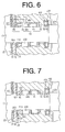
- a second preferred embodiment according to the present invention in a variable displacement piston type compressor will now be described with reference to FIG. 6.
- the same reference numerals of the first preferred embodiment are applied to substantially the same elements in the second preferred embodiment.
- a shaft seal 44A is placed in the accommodation chamber 241.
- the shaft seal 44A prevents the refrigerant in the accommodation chamber 241 from leaking to the suction chamber 111 along the circumferential surface 133 of the drive shaft 13.
- the accommodation chamber 241 and the suction chamber 111 are connected by a refrigerant passage 48 formed in the cylinder block 19 and a throttled passage 49 formed through the valve port plate 20.
- a first end 481 of the refrigerant passage 48 is opened relatively upward in the accommodation chamber 241.
- a clearance S2 is defined between an inner circumferential surface of a race 431 of the thrust bearing 43 and the circumferential surface 133 of the drive shaft 13.
- the refrigerant in the crank chamber 121 flows to the suction chamber 111 through a bleed passage 50 constituted of a gap between the race 431 and a race 432 of the thrust bearing 43, the clearance S2, the clearance S1, a gap in the radial bearing 41, the accommodation chamber 241, the refrigerant passage 48 and the throttled passage 49.
- a third preferred embodiment according to the present invention in a variable displacement piston type compressor will now be described with reference to FIG. 7.
- the same reference numerals of the first preferred embodiment are applied to substantially the same elements in the third preferred embodiment.
- An annular blocking body 51 made of synthetic resin is placed in the accommodation chamber 241.
- the blocking body 51 is made of polytetrafluoroethylene.
- the blocking body 51 is slidable respective to the circumferential surface in the accommodation chamber 241, the circumferential surface 133 of the drive shaft 13 and the suction valve plate 21.
- Grooves 52 and 521 are formed respectively on the outer circumferential surface 512 and the end surface 513 of the blocking body 51.
- the refrigerant in the crank chamber 121 flows to the suction chamber 111 through the gap in the thrust bearing 43, the clearances S2 and S1, the gap in the thrust bearing 41, the accommodation chamber 241, the grooves 52 and 521, and the shaft hole 203.
- the pressure in the crank chamber 121 is adjusted by the outflow of the refrigerant in the crank chamber 121 (or the release of the pressure in the crank chamber 121) through the grooves 52 and 521 of the blocking body 51 that are throttling means.
- the grooves 52 and 521 of the blocking body 51 function as a throttle so as to separate the pressure in the suction chamber 111 from the pressure in the crank chamber 121.
- a bleed passage that linearly extends through the cylinder block 19, the suction valve plate 21, the valve port plate 20 and the discharge valve plate 22 may connect with the crank chamber 121 and the suction chamber 111.
- the refrigerant passage 48 and the throttled passage 49 may be omitted.
- a throttled passage may be formed in the shaft seal 44A.
- a blocking body 51 made of rubber may be employed.
- a nitrile-butadiene rubber may be employed.
- the nitrile-butadiene rubber that is excellent in a resistance to deterioration relative to refrigerant and lubricant oil is suitable for a material of the blocking body 51. While the blocking body 51 made of rubber is formed by molding, the elastic deformation of rubber allows rubber to be lower accuracy in size than synthetic resin. Therefore, the blocking body 51 made of rubber is manufactured more easily than a blocking body made of synthetic resin.
Applications Claiming Priority (2)
| Application Number | Priority Date | Filing Date | Title |
|---|---|---|---|
| JP2001244759A JP2003056460A (ja) | 2001-08-10 | 2001-08-10 | 可変容量型ピストン式圧縮機における流路構造 |
| JP2001244759 | 2001-08-10 |
Publications (2)
| Publication Number | Publication Date |
|---|---|
| EP1283360A2 true EP1283360A2 (fr) | 2003-02-12 |
| EP1283360A3 EP1283360A3 (fr) | 2004-07-21 |
Family
ID=19074642
Family Applications (1)
| Application Number | Title | Priority Date | Filing Date |
|---|---|---|---|
| EP02017854A Withdrawn EP1283360A3 (fr) | 2001-08-10 | 2002-08-08 | Structure de conduit pour compresseur à capacité variable |
Country Status (3)
| Country | Link |
|---|---|
| US (1) | US20030035732A1 (fr) |
| EP (1) | EP1283360A3 (fr) |
| JP (1) | JP2003056460A (fr) |
Cited By (1)
| Publication number | Priority date | Publication date | Assignee | Title |
|---|---|---|---|---|
| US7178450B1 (en) | 2005-10-06 | 2007-02-20 | Delphi Technologies, Inc. | Sealing system for a compressor |
Families Citing this family (2)
| Publication number | Priority date | Publication date | Assignee | Title |
|---|---|---|---|---|
| JP4826948B2 (ja) * | 2005-10-06 | 2011-11-30 | 株式会社ヴァレオジャパン | ピストン型圧縮機 |
| JP6136906B2 (ja) * | 2013-12-11 | 2017-05-31 | 株式会社豊田自動織機 | 容量可変型斜板式圧縮機 |
Citations (6)
| Publication number | Priority date | Publication date | Assignee | Title |
|---|---|---|---|---|
| EP0896155A2 (fr) * | 1997-08-08 | 1999-02-10 | Sanden Corporation | Compresseur à capacité variable dont le réglage de la capacité est amélioré en phase initiale de son démarrage |
| EP0935107A2 (fr) * | 1998-02-06 | 1999-08-11 | Kabushiki Kaisha Toyoda Jidoshokki Seisakusho | Procédé et dispositif pour régler un compresseur à refoulement variable |
| EP0952346A2 (fr) * | 1998-04-14 | 1999-10-27 | Kabushiki Kaisha Toyoda Jidoshokki Seisakusho | Compresseur en plateau en biais à capacité constante ou variable |
| EP1039129A2 (fr) * | 1999-03-15 | 2000-09-27 | Kabushiki Kaisha Toyoda Jidoshokki Seisakusho | Dispositif et procédé de régulation du débit d'un compresseur à capacité variable |
| EP1065375A2 (fr) * | 1999-06-29 | 2001-01-03 | Kabushiki Kaisha Toyoda Jidoshokki Seisakusho | Régulation de pression dans la chambre de bielle d'un compresseur à plateau en biais |
| EP1113235A1 (fr) * | 1999-12-27 | 2001-07-04 | Kabushiki Kaisha Toyoda Jidoshokki Seisakusho | Système de conditionnement d'air |
Family Cites Families (2)
| Publication number | Priority date | Publication date | Assignee | Title |
|---|---|---|---|---|
| JP2000186668A (ja) * | 1998-12-22 | 2000-07-04 | Toyota Autom Loom Works Ltd | 可変容量型圧縮機における容量制御構造 |
| KR100389013B1 (ko) * | 2000-01-11 | 2003-06-25 | 가부시키가이샤 도요다 지도숏키 | 피스톤식 압축기 및 그 조립방법 |
-
2001
- 2001-08-10 JP JP2001244759A patent/JP2003056460A/ja active Pending
-
2002
- 2002-08-08 EP EP02017854A patent/EP1283360A3/fr not_active Withdrawn
- 2002-08-08 US US10/215,702 patent/US20030035732A1/en not_active Abandoned
Patent Citations (6)
| Publication number | Priority date | Publication date | Assignee | Title |
|---|---|---|---|---|
| EP0896155A2 (fr) * | 1997-08-08 | 1999-02-10 | Sanden Corporation | Compresseur à capacité variable dont le réglage de la capacité est amélioré en phase initiale de son démarrage |
| EP0935107A2 (fr) * | 1998-02-06 | 1999-08-11 | Kabushiki Kaisha Toyoda Jidoshokki Seisakusho | Procédé et dispositif pour régler un compresseur à refoulement variable |
| EP0952346A2 (fr) * | 1998-04-14 | 1999-10-27 | Kabushiki Kaisha Toyoda Jidoshokki Seisakusho | Compresseur en plateau en biais à capacité constante ou variable |
| EP1039129A2 (fr) * | 1999-03-15 | 2000-09-27 | Kabushiki Kaisha Toyoda Jidoshokki Seisakusho | Dispositif et procédé de régulation du débit d'un compresseur à capacité variable |
| EP1065375A2 (fr) * | 1999-06-29 | 2001-01-03 | Kabushiki Kaisha Toyoda Jidoshokki Seisakusho | Régulation de pression dans la chambre de bielle d'un compresseur à plateau en biais |
| EP1113235A1 (fr) * | 1999-12-27 | 2001-07-04 | Kabushiki Kaisha Toyoda Jidoshokki Seisakusho | Système de conditionnement d'air |
Cited By (1)
| Publication number | Priority date | Publication date | Assignee | Title |
|---|---|---|---|---|
| US7178450B1 (en) | 2005-10-06 | 2007-02-20 | Delphi Technologies, Inc. | Sealing system for a compressor |
Also Published As
| Publication number | Publication date |
|---|---|
| US20030035732A1 (en) | 2003-02-20 |
| JP2003056460A (ja) | 2003-02-26 |
| EP1283360A3 (fr) | 2004-07-21 |
Similar Documents
| Publication | Publication Date | Title |
|---|---|---|
| KR100203975B1 (ko) | 캠 플레이트식 가변용량 압축기 | |
| EP0940581B1 (fr) | Amortisseur des pulsations de pression pour le réfoulement d'un compresseur | |
| JP6477441B2 (ja) | 可変容量型斜板式圧縮機 | |
| US7972119B2 (en) | Variable displacement compressor | |
| EP2096308B1 (fr) | Compresseur à déplacement variable de type brise-flot | |
| KR19990044689A (ko) | 압축기의 축 밀봉구조 | |
| US6592337B2 (en) | Shaft seal of a lip type with fluid guiding components having the same | |
| KR100202784B1 (ko) | 가변용량 압축기 | |
| US20090223244A1 (en) | Swash plate type compressor | |
| EP1447562B1 (fr) | Compresseur avec structure de lubrification | |
| EP0704622B1 (fr) | Mécanisme d'aspiration à soupape pour un compresseur de réfrigérant | |
| EP1197659B1 (fr) | Refroidissement du système d'étanchéité d'un compresseur à plateau en biais | |
| EP0855505A2 (fr) | Compresseur à déplacement variable | |
| US5498140A (en) | Variable displacement compressor | |
| US20150167655A1 (en) | Variable displacement swash plate type compressor | |
| EP1172557A2 (fr) | Compresseur à plateau en biais | |
| US5782316A (en) | Reciprocating piston variable displacement type compressor improved to distribute lubricating oil sufficiently | |
| EP1283360A2 (fr) | Structure de conduit pour compresseur à capacité variable | |
| CA2221475C (fr) | Compresseur a cylindree variable | |
| US5378115A (en) | Swash plate type compressor | |
| EP1288496A2 (fr) | Compresseur à capacité variable | |
| JP3254820B2 (ja) | クラッチレス片側ピストン式可変容量圧縮機 | |
| EP1065375A2 (fr) | Régulation de pression dans la chambre de bielle d'un compresseur à plateau en biais | |
| JPH0960584A (ja) | 可変容量圧縮機 | |
| EP1092873A2 (fr) | Alésages dans le cylindre d'un compresseur à plateau en biais |
Legal Events
| Date | Code | Title | Description |
|---|---|---|---|
| PUAI | Public reference made under article 153(3) epc to a published international application that has entered the european phase |
Free format text: ORIGINAL CODE: 0009012 |
|
| 17P | Request for examination filed |
Effective date: 20020903 |
|
| AK | Designated contracting states |
Designated state(s): AT BE BG CH CY CZ DE DK EE ES FI FR GB GR IE IT LI LU MC NL PT SE SK TR |
|
| AX | Request for extension of the european patent |
Extension state: AL LT LV MK RO SI |
|
| PUAL | Search report despatched |
Free format text: ORIGINAL CODE: 0009013 |
|
| STAA | Information on the status of an ep patent application or granted ep patent |
Free format text: STATUS: THE APPLICATION HAS BEEN WITHDRAWN |
|
| AK | Designated contracting states |
Kind code of ref document: A3 Designated state(s): AT BE BG CH CY CZ DE DK EE ES FI FR GB GR IE IT LI LU MC NL PT SE SK TR |
|
| AX | Request for extension of the european patent |
Extension state: AL LT LV MK RO SI |
|
| 18W | Application withdrawn |
Effective date: 20040708 |