EP0896139A2 - Verfahren zum Betrieb einer Brennkraftmaschine - Google Patents
Verfahren zum Betrieb einer Brennkraftmaschine Download PDFInfo
- Publication number
- EP0896139A2 EP0896139A2 EP98113922A EP98113922A EP0896139A2 EP 0896139 A2 EP0896139 A2 EP 0896139A2 EP 98113922 A EP98113922 A EP 98113922A EP 98113922 A EP98113922 A EP 98113922A EP 0896139 A2 EP0896139 A2 EP 0896139A2
- Authority
- EP
- European Patent Office
- Prior art keywords
- exhaust gas
- combustion engine
- internal combustion
- gas recirculation
- inlet line
- Prior art date
- Legal status (The legal status is an assumption and is not a legal conclusion. Google has not performed a legal analysis and makes no representation as to the accuracy of the status listed.)
- Granted
Links
Images
Classifications
-
- F—MECHANICAL ENGINEERING; LIGHTING; HEATING; WEAPONS; BLASTING
- F02—COMBUSTION ENGINES; HOT-GAS OR COMBUSTION-PRODUCT ENGINE PLANTS
- F02D—CONTROLLING COMBUSTION ENGINES
- F02D41/00—Electrical control of supply of combustible mixture or its constituents
- F02D41/02—Circuit arrangements for generating control signals
- F02D41/14—Introducing closed-loop corrections
- F02D41/1438—Introducing closed-loop corrections using means for determining characteristics of the combustion gases; Sensors therefor
- F02D41/1439—Introducing closed-loop corrections using means for determining characteristics of the combustion gases; Sensors therefor characterised by the position of the sensor
- F02D41/1441—Plural sensors
-
- F—MECHANICAL ENGINEERING; LIGHTING; HEATING; WEAPONS; BLASTING
- F02—COMBUSTION ENGINES; HOT-GAS OR COMBUSTION-PRODUCT ENGINE PLANTS
- F02D—CONTROLLING COMBUSTION ENGINES
- F02D21/00—Controlling engines characterised by their being supplied with non-airborne oxygen or other non-fuel gas
- F02D21/06—Controlling engines characterised by their being supplied with non-airborne oxygen or other non-fuel gas peculiar to engines having other non-fuel gas added to combustion air
- F02D21/08—Controlling engines characterised by their being supplied with non-airborne oxygen or other non-fuel gas peculiar to engines having other non-fuel gas added to combustion air the other gas being the exhaust gas of engine
-
- F—MECHANICAL ENGINEERING; LIGHTING; HEATING; WEAPONS; BLASTING
- F02—COMBUSTION ENGINES; HOT-GAS OR COMBUSTION-PRODUCT ENGINE PLANTS
- F02D—CONTROLLING COMBUSTION ENGINES
- F02D41/00—Electrical control of supply of combustible mixture or its constituents
- F02D41/0025—Controlling engines characterised by use of non-liquid fuels, pluralities of fuels, or non-fuel substances added to the combustible mixtures
- F02D41/0047—Controlling exhaust gas recirculation [EGR]
- F02D41/0065—Specific aspects of external EGR control
- F02D41/0072—Estimating, calculating or determining the EGR rate, amount or flow
-
- F—MECHANICAL ENGINEERING; LIGHTING; HEATING; WEAPONS; BLASTING
- F02—COMBUSTION ENGINES; HOT-GAS OR COMBUSTION-PRODUCT ENGINE PLANTS
- F02D—CONTROLLING COMBUSTION ENGINES
- F02D41/00—Electrical control of supply of combustible mixture or its constituents
- F02D41/02—Circuit arrangements for generating control signals
- F02D41/14—Introducing closed-loop corrections
- F02D41/1438—Introducing closed-loop corrections using means for determining characteristics of the combustion gases; Sensors therefor
- F02D41/1439—Introducing closed-loop corrections using means for determining characteristics of the combustion gases; Sensors therefor characterised by the position of the sensor
- F02D41/144—Sensor in intake manifold
-
- F—MECHANICAL ENGINEERING; LIGHTING; HEATING; WEAPONS; BLASTING
- F02—COMBUSTION ENGINES; HOT-GAS OR COMBUSTION-PRODUCT ENGINE PLANTS
- F02B—INTERNAL-COMBUSTION PISTON ENGINES; COMBUSTION ENGINES IN GENERAL
- F02B29/00—Engines characterised by provision for charging or scavenging not provided for in groups F02B25/00, F02B27/00 or F02B33/00 - F02B39/00; Details thereof
- F02B29/04—Cooling of air intake supply
- F02B29/0406—Layout of the intake air cooling or coolant circuit
-
- F—MECHANICAL ENGINEERING; LIGHTING; HEATING; WEAPONS; BLASTING
- F02—COMBUSTION ENGINES; HOT-GAS OR COMBUSTION-PRODUCT ENGINE PLANTS
- F02D—CONTROLLING COMBUSTION ENGINES
- F02D41/00—Electrical control of supply of combustible mixture or its constituents
- F02D41/0002—Controlling intake air
- F02D2041/0017—Controlling intake air by simultaneous control of throttle and exhaust gas recirculation
-
- F—MECHANICAL ENGINEERING; LIGHTING; HEATING; WEAPONS; BLASTING
- F02—COMBUSTION ENGINES; HOT-GAS OR COMBUSTION-PRODUCT ENGINE PLANTS
- F02M—SUPPLYING COMBUSTION ENGINES IN GENERAL WITH COMBUSTIBLE MIXTURES OR CONSTITUENTS THEREOF
- F02M26/00—Engine-pertinent apparatus for adding exhaust gases to combustion-air, main fuel or fuel-air mixture, e.g. by exhaust gas recirculation [EGR] systems
- F02M26/02—EGR systems specially adapted for supercharged engines
- F02M26/04—EGR systems specially adapted for supercharged engines with a single turbocharger
- F02M26/05—High pressure loops, i.e. wherein recirculated exhaust gas is taken out from the exhaust system upstream of the turbine and reintroduced into the intake system downstream of the compressor
-
- F—MECHANICAL ENGINEERING; LIGHTING; HEATING; WEAPONS; BLASTING
- F02—COMBUSTION ENGINES; HOT-GAS OR COMBUSTION-PRODUCT ENGINE PLANTS
- F02M—SUPPLYING COMBUSTION ENGINES IN GENERAL WITH COMBUSTIBLE MIXTURES OR CONSTITUENTS THEREOF
- F02M26/00—Engine-pertinent apparatus for adding exhaust gases to combustion-air, main fuel or fuel-air mixture, e.g. by exhaust gas recirculation [EGR] systems
- F02M26/13—Arrangement or layout of EGR passages, e.g. in relation to specific engine parts or for incorporation of accessories
- F02M26/22—Arrangement or layout of EGR passages, e.g. in relation to specific engine parts or for incorporation of accessories with coolers in the recirculation passage
- F02M26/23—Layout, e.g. schematics
-
- Y—GENERAL TAGGING OF NEW TECHNOLOGICAL DEVELOPMENTS; GENERAL TAGGING OF CROSS-SECTIONAL TECHNOLOGIES SPANNING OVER SEVERAL SECTIONS OF THE IPC; TECHNICAL SUBJECTS COVERED BY FORMER USPC CROSS-REFERENCE ART COLLECTIONS [XRACs] AND DIGESTS
- Y02—TECHNOLOGIES OR APPLICATIONS FOR MITIGATION OR ADAPTATION AGAINST CLIMATE CHANGE
- Y02T—CLIMATE CHANGE MITIGATION TECHNOLOGIES RELATED TO TRANSPORTATION
- Y02T10/00—Road transport of goods or passengers
- Y02T10/10—Internal combustion engine [ICE] based vehicles
- Y02T10/40—Engine management systems
Definitions
- the invention relates to a method for operating a Internal combustion engine and one for performing the method suitable internal combustion engine according to the generic terms of the independent Claims 1 and 8.
- the exhaust gas recirculation is Known as an effective means of reducing emissions.
- the recirculation rate of the exhaust gas i.e. H. the Amount of the proportion of fresh air flow in the inlet line admixed exhaust gas flow in relation to the amount of combustion air, is adjusted by a controller unit Specified setpoints depending on the operating point.
- EP-0 574 614 A1 describes a method for regulating the Exhaust gas recirculation rate known to determine the Actual value of the recirculated exhaust gas mass flow the pressure drop on a venturi in the exhaust gas recirculation duct measures and determines the flow from the pressure difference.
- the backflow of the exhaust gas through the exhaust gas recirculation channel of the pressure drop between the exhaust pipe and Inlet line of the internal combustion engine is reduced the pressure loss at the venturi nozzle that for recirculation available pressure drops.
- the possible exhaust gas recirculation rate is reduced and it can be in many operating points of the internal combustion engine are not the optimum Reduction of exhaust emissions can be achieved.
- the invention has for its object a maximum Emission reduction of the internal combustion engine through exhaust gas recirculation with the most accurate recording and control of the To allow exhaust gas recirculation rate.
- the hydrocarbons of the fuel with the release of energy chemically associated with oxygen.
- the exhaust gas therefore contains significantly less oxygen than fresh air, which the internal combustion engine when changing charges is fed.
- the recirculation of the low-oxygen exhaust gas leads to a reduction in the oxygen concentration in the ultimately combustion air flow supplied to the internal combustion engine compared to the fresh air drawn in.
- the invention is in the gas streams before and after the confluence of the exhaust gas recirculation channel in the inlet line the respective oxygen content of accordingly in the respective Gas flow protruding oxygen sensors measured.
- the measurement signals from the oxygen sensors become the input side fed to the controller unit, which from the measurement results determines the difference in oxygen concentrations and from this the present recirculation rate in exhaust gas recirculation mode the internal combustion engine determined.
- the respective oxygen contents are measured in the Combustion air flow before entering the internal combustion engine on the one hand and in the exhaust gas flow on the other hand, whereby the amount of exhaust gas recirculated from the measurement results Can be determined precisely due to physical relationships is.
- the controller unit can determine the combustion air ratio in the mixture formation in the internal combustion engine regulate, d. H. the ratio of those during the combustion process available amount of oxygen to the required Amount for a complete fuel combustion, being the controller unit controls another actuator which on the fresh air flow before the confluence of the recirculated Exhaust gas flow acts.
- the actuator can Throttle valve in the inlet line or for example when using the invention for charged Internal combustion engines have a variable turbine geometry of the exhaust gas turbolator.
- a particularly precise regulation of the combustion air ratio is achieved if the controller unit alternatively or in addition to the actuator with effect on the fresh air flow sets the fuel metering.
- the controller unit is dependent on the operating point a setpoint of the combustion air ratio given which, based on the precise recording of the Recirculation rate in the range of the maximum traceable exhaust gas quantity lies.
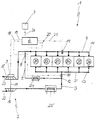
- the only drawing figure shows a supercharged internal combustion engine 1 with six cylinders Z1 to Z6 in a row arrangement.
- Each of the cylinders Z1 to Z6 is each one Cylinder inlet 13 is supplied with combustion air.
- the exhaust gases are each pushed out via a cylinder outlet 14 and discharged through a common exhaust pipe 4.
- a Exhaust gas turbocharger 2 compresses atmospheric fresh air 22 and pushes the charge air into an inlet line 3 Charge air line 3 ', which the cylinder inlets 13 of all Cylinder Z1 to Z6 feeds.
- a turbine 15 of the exhaust gas turbocharger 2 is arranged in the exhaust pipe 4 in a known manner and is flowed through by the exhaust gas stream 23.
- a Charger shaft 17 drives the turbine 15 a charge air compressor 16 on.
- a charge air cooler 25 arranged, which precedes the compressed fresh air flow cools the entry into the charge air line 3 '.
- the flow cross section the turbine 15 of the exhaust gas turbocharger 2 is through corresponding control measures on a guide device 9 variable adjustable. By adjusting the turbine guide vane The speed is determined by the guide device 9 of the turbine the mechanically rigidly connected via the loader shaft 17 Turbomachines 15, 16 and thus the throughput of Fresh air flow 22 at the compressor 16 and the compressor output influenced.
- an exhaust gas recirculation channel 5 is from the exhaust pipe 4 of the internal combustion engine to reduce emissions Partial flow in the inlet line 3 traceable, in particular the temperature-dependent nitrogen oxide emission can be caused by Exhaust gas recirculation operation can be reduced, being in the exhaust gas recirculation channel 5 for cooling the recirculated exhaust gas stream before the confluence with the inlet line 3 and the mixing there with the compacted Fresh air flow an exhaust gas cooler 24 is arranged. After Junction 12 of the exhaust gas recirculation duct 5 into the inlet line 3 flows from fresh air and recirculated exhaust gas existing charge air flow into the charge air line 3 '.
- an exhaust gas recirculation valve 8 with variably adjustable passage cross-section arranged for dosing the amount of recirculated exhaust gas is in the exhaust gas recirculation channel 5 an exhaust gas recirculation valve 8 with variably adjustable passage cross-section arranged.
- the exhaust gas recirculation valve 8 is operated by a control unit controlled with an actuating signal 18, which is dependent generated from the operating point of the internal combustion engine 1 becomes.
- the present operating point of the internal combustion engine during operation, the Controller unit 6 by supplying corresponding operating parameters such as speed, operating load etc. are displayed.
- the maximum The traceable amount of exhaust gas depends on the operating point the internal combustion engine differently, one Exceeding the permissible return rate, i. H. in relation to the amount of exhaust gas added to the fresh air flow a significant deterioration in exhaust gas emissions Increase in the soot content of the exhaust gas and beyond an increase in the fuel consumption of the internal combustion engine leads.
- the recirculation rate is regulated by the controller unit with control measures on the exhaust gas recirculation valve 8 via the control signal 18, the optimum recirculation rate specific to the operating point being specified as a reference variable.
- the controller unit 6 takes the reference variable 26 for the control from a map memory 7, in which the operationally optimal setpoints are stored for a large number of operating points of the internal combustion engine.
- the exact actual value of the recirculation rate is determined by the controller unit 6 from the measurement results of two oxygen sensors 10, 11, which are arranged on the one hand in the inlet line 3 after the junction 12 of the exhaust gas recirculation duct 5 and on the other hand in the exhaust line 4 of the internal combustion engine 1.
- the oxygen measuring probes 10, 11 measure the respective oxygen content of the exhaust gas flow before the junction 12 into the inlet line 3 and the combustion air flow after the junction 12 and each generate a measurement signal 20, 21 which is fed to the controller unit 6 for evaluation.
- the control unit determines the measurement signal 21 from the oxygen sensor 11 in the exhaust line 4 and the measurement signal 20 from the oxygen sensor 10 in the inlet line 3, which represents the oxygen content of the combustion air flow flowing into the cylinders Z1 to Z6, which consists of the compressed fresh air and recirculated exhaust gas 6 the precise actual value of the feedback rate R according to the following assignment rule: where R denotes the ratio of the amount of exhaust gas recirculated to the total amount of combustion air, [11] represents the oxygen content of the exhaust gas flow represented by the measurement signal from the oxygen sensor 11 and [10] represents the oxygen content of the combustion air, which from the measurement signal of the oxygen sensor 10 in the inlet line 3 of the internal combustion engine 1 is determined with a statement about the oxygen content of the combustion air.
- the controller unit pulls 6 the respective difference in the oxygen concentrations between fresh air and combustion air on the one hand and Combustion air and exhaust gas on the other hand to determine the Return rate.
- the exhaust gas recirculation rate R can be in simple Use cases from the measurement results in the structure easier Differential measuring probes are determined, which accordingly are arranged in the lines to be measured and determine the difference between the respective oxygen contents as above.
- the determination of the absolute values of the oxygen content in the combustion air (sensor 10) and in the exhaust gas (sensor 11) also enables the control unit 6 to regulate the combustion air ratio when the mixture is formed in the cylinders Z1 to Z6 of the internal combustion engine 1, including the previously precisely determined actual value of the recirculation rate R and the oxygen content in the exhaust gas.
- the controller unit generates an actuating signal 19 for the guide device 9 of the exhaust gas turbocharger 2 and acts on the fresh air mass flow 22 on the compressor side via the inflow cross section of the turbine 15 for the exhaust gas flow.
- the combustion air ratio is adjusted to a setpoint-specific setpoint which, like the setpoints of the feedback rate, is taken from the map memory 7.
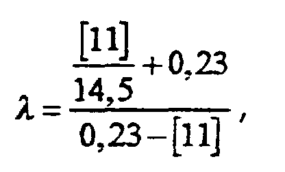
- the exact actual value of the combustion air ratio ⁇ EGR in exhaust gas recirculation mode is determined using the previously determined recirculation rate R according to the following size equation: ⁇ denotes the combustion air ratio without taking into account the additional oxygen returned via the return duct 5.
- the controller unit 6 regulates the in each operating point Internal combustion engine the maximum feedback rate and the optimal Combustion air ratio and generates corresponding Control signals 18, 19 for the exhaust gas recirculation valve actuators 8 and turbine guide grill 9. Since the recirculation rate and the combustion air ratio at the same time and are mutually dependent, is also such operating points the internal combustion engine in which the required Air ratio through two different inflow cross sections the turbine 15 of the exhaust gas turbocharger 2 can be generated is a position of the guide device 9 clearly assignable, namely exactly which of the targeted return rate corresponds.
- the determination and regulation of the return rate according to the invention is feasible with little construction and is also particularly suitable for retrofitting in Operation of controlled exhaust gas recirculation devices.
- the efficiency of internal combustion engines with Exhaust gas recirculation devices can with the invention Procedures can be increased significantly.
- the exact determination the return rate from the measurement results of the oxygen sensors 10, 11, which the oxygen content in the Gas flows before and after the opening of the exhaust gas recirculation channel measuring in the inlet pipe is in principle regardless of the type of feedback device, d. H. their actuators.
Landscapes
- Engineering & Computer Science (AREA)
- Chemical & Material Sciences (AREA)
- Combustion & Propulsion (AREA)
- Mechanical Engineering (AREA)
- General Engineering & Computer Science (AREA)
- Exhaust-Gas Circulating Devices (AREA)
- Output Control And Ontrol Of Special Type Engine (AREA)
Abstract
Description


Claims (7)
- Verfahren zum Betrieb einer Brennkraftmaschine, wobei zur Emissionssenkung Abgas durch einen Abgasrückführungskanal (5) aus einer Abgasleitung (4) der Brennkraftmaschine (1) in eine Einlaßleitung (3) rückgeführt wird und eine Reglereinheit (6) die Rückführrate (R) des dem Frischluftstrom in der Einlaßleitung (3) anteilig beigemischten Abgasstroms unter Angleich eines ermittelten Ist-Wertes an betriebspunktabhängig vorgegebene Sollwerte regelt und ein Abgasrückführungsventil (8) mit variabel einstellbarem Durchgangsquerschnitt ansteuert,
dadurch gekennzeichnet, daß in den Gasströmen jeweils vor und nach einer Einmündung (12) des Abgasrückführungskanals (5) in die Einlaßleitung (3) der jeweilige Sauerstoffgehalt gemessen wird und die Reglereinheit (6) aus den Messergebnissen die vorliegende Rückführrate (R) ermittelt. - Verfahren nach Anspruch 1,
dadurch gekennzeichnet, daß die Messungen der jeweiligen Sauerstoffgehalte im Verbrennungsluftstrom vor dem Eintritt in die Brennkraftmaschine (1) einerseits und im Abgasstrom (23) andererseits erfolgen. - Verfahren nach Anspruch 1 oder 2,
dadurch gekennzeichnet, daß die jeweilige Differenz der Sauerstoffkonzentrationen zwischen Frischluftstrom (22) mit Verbrennungsluftstrom vor dem Eintritt in die Brennkraftmaschine einerseits sowie zwischen Verbrennungsluftstrom und Abgasstrom 23 andererseits zur Ermittlung der Regelgröße herangezogen wird. - Verfahren nach einem der Ansprüche 1 bis 3,
dadurch gekennzeichnet, daß die Reglereinheit (6) ein weiteres Stellglied (9) mit Wirkung auf den Frischluftmassenstrom (22) vor der Einmündung (12) des Abgasrückführungskanals (5) ansteuert und unter Einbeziehung der Rückführungsrate (R) und des Sauerstoffgehaltes im Abgasstrom (23) das Verbrennungsluftverhältnis (λAGR) bei der Gemischbildung in der Brennkraftmaschine regelt, wobei der Reglereinheit (6) Sollwerte des Verbrennungsluftverhältnisses (λAGR) in Abhängigkeit vom Betriebspunkt vorgegeben werden. - Verfahren nach Anspruch 4,
dadurch gekennzeichnet, daß die Reglereinheit (6) im Regelkreis des Verbrennungsluftverhältnisses (λAGR) alternativ oder zusätzlich zum Stellglied (9) mit Wirkung auf den Frischluftmassenstrom (22) die Kraftstoffzumessung einstellt. - Verfahren nach einem der Ansprüche 1 bis 5,
dadurch gekennzeichnet, daß in einem Kennfeldspeicher (7) für eine Vielzahl von Betriebspunkten der Brennkraftmaschine (1) die betriebsoptimalen Sollwerte abgelegt sind, welche die Reglereinheit (6) bedarfsweise als Führungsgröße (26) für die Regelung entnimmt. - Brennkraftmaschine mit einem Abgasrückführungskanal (5) zwischen einer Abgasleitung (4) und einer Einlaßleitung (3), wobei in dem Abgasrückführungskanal (5) ein Abgasrückführungsventil (8) mit variabel einstellbarem Durchgangsquerschnitt angeordnet ist, welches von einer Reglereinheit (6) zur Regelung der Rückführrate (R) des dem Frischluftstrom in der Einlaßleitung (3) anteilig beigemischten Abgasstroms über ein Stellsignal (18) ansteuerbar ist,
dadurch gekennzeichnet, daß ein Sauerstoffsensor (10) in der Einlaßleitung (3) nach einer Einmündung (12) des Abgasrückführungskanals (5) und ein weiterer Sauerstoffsensor (11) in einer abgasführenden Leitung (4, 5) angeordnet ist und signalübertragend mit einer Eingangsseite der Reglereinheit (6) verbunden ist.
Applications Claiming Priority (2)
| Application Number | Priority Date | Filing Date | Title |
|---|---|---|---|
| DE19734494A DE19734494C1 (de) | 1997-08-08 | 1997-08-08 | Verfahren zum Betrieb einer Brennkraftmaschine |
| DE19734494 | 1997-08-08 |
Publications (3)
| Publication Number | Publication Date |
|---|---|
| EP0896139A2 true EP0896139A2 (de) | 1999-02-10 |
| EP0896139A3 EP0896139A3 (de) | 1999-12-29 |
| EP0896139B1 EP0896139B1 (de) | 2002-07-03 |
Family
ID=7838460
Family Applications (1)
| Application Number | Title | Priority Date | Filing Date |
|---|---|---|---|
| EP98113922A Expired - Lifetime EP0896139B1 (de) | 1997-08-08 | 1998-07-24 | Verfahren zum Betrieb einer Brennkraftmaschine |
Country Status (3)
| Country | Link |
|---|---|
| US (1) | US6029451A (de) |
| EP (1) | EP0896139B1 (de) |
| DE (2) | DE19734494C1 (de) |
Cited By (1)
| Publication number | Priority date | Publication date | Assignee | Title |
|---|---|---|---|---|
| EP4261393A1 (de) | 2022-04-11 | 2023-10-18 | Winterthur Gas & Diesel Ltd. | Verbrennungsmotor |
Families Citing this family (49)
| Publication number | Priority date | Publication date | Assignee | Title |
|---|---|---|---|---|
| JP3430923B2 (ja) * | 1998-06-15 | 2003-07-28 | 日産自動車株式会社 | 内燃機関の過給制御装置 |
| DE19858293C1 (de) * | 1998-12-17 | 2000-03-09 | Daimler Chrysler Ag | Brennkraftmaschine mit einem Abgasturbolader mit variabler Turbinengeometrie |
| US6178749B1 (en) * | 1999-01-26 | 2001-01-30 | Ford Motor Company | Method of reducing turbo lag in diesel engines having exhaust gas recirculation |
| US6128902A (en) * | 1999-01-26 | 2000-10-10 | Ford Global Technologies, Inc. | Control method and apparatus for turbocharged diesel engines having exhaust gas recirculation |
| DE19912317C9 (de) * | 1999-03-19 | 2004-11-04 | Daimlerchrysler Ag | Verfahren zur Regelung des Anteils der einer Brennkraftmaschine rückgeführten Abgasmenge |
| DE19921494A1 (de) * | 1999-05-08 | 2000-11-09 | Deutz Ag | Verfahren zum Betreiben einer Abgasrückführeinrichtung einer Brennkraftmaschine |
| US6301888B1 (en) | 1999-07-22 | 2001-10-16 | The United States Of America As Represented By The Administrator Of The Environmental Protection Agency | Low emission, diesel-cycle engine |
| DE19936595C1 (de) * | 1999-08-04 | 2000-08-03 | Daimler Chrysler Ag | Verfahren zum Betrieb einer mittels Abgasturbolader aufgeladenen Brennkraftmaschine |
| US6354084B1 (en) * | 1999-08-20 | 2002-03-12 | Cummins Engine Company, Inc. | Exhaust gas recirculation system for a turbocharged internal combustion engine |
| DE19960618B4 (de) * | 1999-12-16 | 2005-02-03 | Daimlerchrysler Ag | Brennkraftmaschine mit einer Einrichtung zur Abgasrückführung und einer variablen Ejektordüse im Ansaugtrakt |
| DE10007010C2 (de) * | 2000-02-16 | 2003-04-17 | Daimler Chrysler Ag | Sensoreinheit zur Bestimmung der Abgasrückführungsrate einer Brennkraftmaschine |
| US6305167B1 (en) * | 2000-03-31 | 2001-10-23 | Detroit Diesel Corporation | Method of controlling an engine with an EGR system |
| ATE307276T1 (de) * | 2000-03-31 | 2005-11-15 | Detroit Diesel Corp | Verfahren zum regeln eines motors mit abgasrückführung |
| DE10048237A1 (de) | 2000-09-29 | 2002-04-11 | Daimler Chrysler Ag | Abgasturbolader, aufgeladene Brennkraftmaschine und Verfahren hierzu |
| ITBO20010010A1 (it) * | 2001-01-12 | 2002-07-12 | Magneti Marelli Spa | Metodo per la stima della quantita' di aria fresca presente nei collettori di respirazione e di scarico di un motore a combustione interna c |
| US6508237B2 (en) | 2001-01-29 | 2003-01-21 | Detroit Diesel Corporation | Exhaust gas recirculation transient smoke control |
| US6666201B1 (en) * | 2002-05-29 | 2003-12-23 | Ford Global Technologies, Llc | System and method for diagnosing EGR performance using NOx sensor |
| DE10233362A1 (de) | 2002-07-23 | 2004-02-12 | Daimlerchrysler Ag | Vorrichtung zur Bestimmung der Abgasrückführungsrate einer Brennkraftmaschine |
| WO2004051069A1 (de) * | 2002-12-03 | 2004-06-17 | Behr Gmbh & Co. Kg | Vorrichtung zur kühlung |
| DE10316112A1 (de) | 2003-04-09 | 2004-10-28 | Daimlerchrysler Ag | Verfahren zum Betrieb einer Brennkraftmaschine mit Selbstzündung |
| DE10316113A1 (de) | 2003-04-09 | 2004-10-28 | Daimlerchrysler Ag | Verfahren zum Betrieb einer Brennkraftmaschine mit Selbstzündung |
| DE10320054A1 (de) * | 2003-05-06 | 2004-11-25 | Robert Bosch Gmbh | Verfahren und Vorrichtung zum Betreiben einer Brennkraftmaschine |
| DE10325413B4 (de) * | 2003-06-05 | 2015-03-05 | Audi Ag | Verfahren zum Betreiben einer Brennkraftmaschine eines Fahrzeuges, insbesondere eines Kraftfahtzeuges sowie Vorrichtung zur Durchführung eines derartigen Verfahrens |
| DE10329441B4 (de) * | 2003-07-01 | 2006-08-03 | Daimlerchrysler Ag | Aufgeladene Brennkraftmaschine |
| EP1559893B1 (de) * | 2004-01-30 | 2006-09-13 | Nissan Motor Co., Ltd. | Vorrichtung und Verfahren zur Steuerung einer Brennkraftmaschine |
| EP1607606B1 (de) * | 2004-06-15 | 2008-04-09 | C.R.F. Società Consortile per Azioni | Verfahren und Einrichtung zur Bestimmung der Ansaugluftmenge einer Brennkraftmaschine basierend auf der Messung der Sauerstoff-Konzentration in einem der Brennkraftmaschine zugeführten Gasgemisch |
| DE102005002246A1 (de) | 2005-01-18 | 2006-07-20 | Daimlerchrysler Ag | Brennkraftmaschine mit einer Abgasrückführungseinrichtung und Verfahren zum Betrieb einer Brennkraftmaschine |
| DE102005012306A1 (de) | 2005-03-17 | 2006-09-28 | Daimlerchrysler Ag | Verfahren zum Betrieb einer Brennkraftmaschine und Brennkraftmaschine hierzu |
| DE102005013977B4 (de) * | 2005-03-26 | 2020-09-03 | Ford Global Technologies, Llc | Abgasrückführsystem für ein Kraftfahrzeug und Verfahren zum Einstellen der Abgasrückführrate in einem Gasrückführsystem |
| US7063076B1 (en) | 2005-05-16 | 2006-06-20 | Detroit Diesel Corporation | Method of smoke limiting engine |
| US20070044472A1 (en) * | 2005-09-01 | 2007-03-01 | Guoqing Zhang | Oxygen sensor for an internal combustion engine |
| DE102006026219B4 (de) * | 2006-06-06 | 2016-01-07 | Continental Automotive Gmbh | Verfahren und Vorrichtung zum Betreiben einer Brennkraftmaschine |
| DE102007060036B4 (de) | 2007-12-13 | 2010-01-07 | Continental Automotive Gmbh | Verfahren zur Bestimmung von korrigierten Messwerten und/oder Modellparametern zur Steuerung des Luftpfads von Verbrennungsmotoren |
| DE102010035364B4 (de) | 2010-08-25 | 2017-07-13 | Audi Ag | Vorrichtung zum Betreiben einer Brennkraftmaschine |
| DE102011115364A1 (de) * | 2010-10-19 | 2012-04-19 | Alstom Technology Ltd. | Kraftwerk |
| US9267449B2 (en) | 2011-06-16 | 2016-02-23 | GM Global Technology Operations LLC | Control system and method for coordinating throttle and boost |
| US9157390B2 (en) | 2011-09-21 | 2015-10-13 | GM Global Technology Operations LLC | Selective exhaust gas recirculation diagnostic systems and methods |
| DE102012200062B4 (de) * | 2012-01-03 | 2015-07-23 | Continental Automotive Gmbh | Brennkraftmaschine mit im Luftansaugtrakt angeordnetem Sauerstoffsensor und Sauerstoffsensor |
| US10066564B2 (en) | 2012-06-07 | 2018-09-04 | GM Global Technology Operations LLC | Humidity determination and compensation systems and methods using an intake oxygen sensor |
| US9249764B2 (en) | 2012-03-06 | 2016-02-02 | GM Global Technology Operations LLC | Engine control systems and methods with humidity sensors |
| US9932917B2 (en) | 2012-03-21 | 2018-04-03 | GM Global Technology Operations LLC | Exhaust gas recirculation control systems and methods |
| US20130268176A1 (en) * | 2012-04-05 | 2013-10-10 | GM Global Technology Operations LLC | Exhaust gas recirculation control systems and methods for low engine delta pressure conditions |
| US20140025280A1 (en) * | 2012-07-18 | 2014-01-23 | Delphi Technologies, Inc. | System and method to determine restriction of individual exhaust gas recirculation runners |
| US9341133B2 (en) | 2013-03-06 | 2016-05-17 | GM Global Technology Operations LLC | Exhaust gas recirculation control systems and methods |
| US9188087B2 (en) * | 2013-03-07 | 2015-11-17 | Ford Global Technologies, Llc | Ejector flow rate computation for gas constituent sensor compensation |
| US9228524B2 (en) | 2013-08-15 | 2016-01-05 | GM Global Technology Operations LLC | Static and dynamic pressure compensation for intake oxygen sensing |
| US9683497B2 (en) * | 2013-10-25 | 2017-06-20 | Ford Global Technologies, Llc | Methods and systems for adjusting engine airflow based on output from an oxygen sensor |
| JP6707038B2 (ja) * | 2017-01-23 | 2020-06-10 | 日立オートモティブシステムズ株式会社 | 内燃機関の制御装置 |
| JP6320587B1 (ja) * | 2017-03-08 | 2018-05-09 | 三菱電機株式会社 | 内燃機関の制御装置及び制御方法 |
Citations (2)
| Publication number | Priority date | Publication date | Assignee | Title |
|---|---|---|---|---|
| EP0574614A1 (de) | 1992-06-19 | 1993-12-22 | Bundy Corporation | Verbindungskupplung mit Messblende für Abgasrückführung |
| DE4337313C1 (de) | 1993-11-02 | 1995-03-02 | Daimler Benz Ag | Vorrichtung zur Bestimmung eines Gasmassendurchsatzes einer Brennkraftmaschine |
Family Cites Families (8)
| Publication number | Priority date | Publication date | Assignee | Title |
|---|---|---|---|---|
| JPS5855345B2 (ja) * | 1976-11-30 | 1983-12-09 | 日産自動車株式会社 | 排気還流制御装置 |
| DE2911209A1 (de) * | 1979-03-22 | 1980-10-02 | Bosch Gmbh Robert | Einrichtung zum regeln der abgasrueckfuehrrate bei einer brennkraftmaschine |
| US4614175A (en) * | 1983-12-27 | 1986-09-30 | Mitsubishi Denki Kabushiki Kaisha | Engine exhaust gas recirculation control system |
| JPS62189358A (ja) * | 1986-02-14 | 1987-08-19 | Mitsubishi Electric Corp | 機関の排気ガス還流量制御装置 |
| KR920004491B1 (ko) * | 1987-05-21 | 1992-06-05 | 미쓰비시전기 주식회사 | 기관제어장치 |
| JPH0518324A (ja) * | 1991-07-12 | 1993-01-26 | Mitsubishi Electric Corp | 機関の排気ガス再循環制御装置 |
| JP3298358B2 (ja) * | 1995-04-25 | 2002-07-02 | 日産自動車株式会社 | ディーゼルエンジンにおける圧縮端温度制御方法および制御装置 |
| JP3518203B2 (ja) * | 1996-11-14 | 2004-04-12 | トヨタ自動車株式会社 | Egr装置付き内燃機関 |
-
1997
- 1997-08-08 DE DE19734494A patent/DE19734494C1/de not_active Expired - Fee Related
-
1998
- 1998-07-24 EP EP98113922A patent/EP0896139B1/de not_active Expired - Lifetime
- 1998-07-24 DE DE59804637T patent/DE59804637D1/de not_active Expired - Fee Related
- 1998-08-07 US US09/131,001 patent/US6029451A/en not_active Expired - Lifetime
Patent Citations (2)
| Publication number | Priority date | Publication date | Assignee | Title |
|---|---|---|---|---|
| EP0574614A1 (de) | 1992-06-19 | 1993-12-22 | Bundy Corporation | Verbindungskupplung mit Messblende für Abgasrückführung |
| DE4337313C1 (de) | 1993-11-02 | 1995-03-02 | Daimler Benz Ag | Vorrichtung zur Bestimmung eines Gasmassendurchsatzes einer Brennkraftmaschine |
Cited By (1)
| Publication number | Priority date | Publication date | Assignee | Title |
|---|---|---|---|---|
| EP4261393A1 (de) | 2022-04-11 | 2023-10-18 | Winterthur Gas & Diesel Ltd. | Verbrennungsmotor |
Also Published As
| Publication number | Publication date |
|---|---|
| DE59804637D1 (de) | 2002-08-08 |
| US6029451A (en) | 2000-02-29 |
| EP0896139A3 (de) | 1999-12-29 |
| EP0896139B1 (de) | 2002-07-03 |
| DE19734494C1 (de) | 1998-10-08 |
Similar Documents
| Publication | Publication Date | Title |
|---|---|---|
| EP0896139B1 (de) | Verfahren zum Betrieb einer Brennkraftmaschine | |
| DE102005013977B4 (de) | Abgasrückführsystem für ein Kraftfahrzeug und Verfahren zum Einstellen der Abgasrückführrate in einem Gasrückführsystem | |
| DE69923341T2 (de) | Verfahren und vorrichtung für ein abgasrückführungssystem und zugehöriges ventil | |
| DE602004012986T2 (de) | Verfahren und Einrichtung zur Bestimmung der Ansaugluftmenge einer Brennkraftmaschine basierend auf der Messung der Sauerstoffkonzentration in einem der Brennkraftmaschine zugeführten Gasgemisch | |
| DE3220832C2 (de) | ||
| AT391556B (de) | Verfahren und einrichtung zur stetigen entnahme einer teilmenge aus einem gasstrom | |
| DE19603472C2 (de) | Verfahren zur Steuerung einer Abgasrückführvorrichtung einer Brennkraftmaschine | |
| DE19959854A1 (de) | Verfahren zur Abgasrückführung in einem Luftansaugbereich von Fahrzeug-Brennkraftmaschinen sowie Vorrichtung | |
| DE10349490A1 (de) | System und Verfahren für die Schätzung und Regelung der Zylinderluftladung bei einem Innenverbrennungsmotor mit Direkteinspritzung | |
| DE19628852A1 (de) | Abgasrezirkulationssystem für einen Kompressionszündmotor und Verfahren zur Steuerung von Abgasrezirkulation in einem Kompressionszündmotor | |
| DE102011003095A1 (de) | Verfahren zur Ermittlung der SauerstoffkonzentrationO2 in einer Gasströmung und Sauerstoffsensor zur Durchführung des Verfahrens | |
| DE102005060350A1 (de) | Verfahren zur Regelung eines Verbrennungsprozesses einer Brennkraftmaschine mit Abgasrückführung | |
| DE19710840A1 (de) | Verfahren und Vorrichtung zur Anreicherung des Sauerstoff-Gehalts in der Ansaugluft eines Verbrennungsmotors | |
| DE19622891A1 (de) | Abgasrückführungssystem | |
| DE19502368B4 (de) | Verfahren zur Bildung eines Signals bezüglich der bei einer Brennkraftmaschine rückgeführten Abgasmenge | |
| EP1091106B1 (de) | Verfahren zur Bestimmung eines Abgasgegendruckes an einer Turbine | |
| DE19912317A1 (de) | Verfahren zur Regelung des Anteils der einer Brennkraftmaschine rückgeführten Abgasmenge | |
| WO2003078816A1 (de) | VERFAHREN UND EINRICHTUNG ZUR ÜBERWACHUNG UND REGELUNG DES BETRIEBES EINER BRENNKRAFTMASCHINE MIT REDUZIERTER NOx-EMISSION | |
| EP0252316B1 (de) | Brennkraftmaschine mit Druckwellenlader und Lamda-Sonde | |
| DE10256241A1 (de) | Verfahren und Vorrichtung zur Steuerung einer eine Abgasrückführung aufweisenden Brennkraftmaschine | |
| DE3036508C2 (de) | Mehrzylindrige Kolbenbrennkraftmaschine, insbesondere fremdgezündete Einspritzbrennkraftmaschine | |
| EP1417405A1 (de) | Verfahren zur regelung eines verbrennungsmotors mit abgasrückführung sowie einrichtung zur durchführung des verfahrens | |
| DE19936595C1 (de) | Verfahren zum Betrieb einer mittels Abgasturbolader aufgeladenen Brennkraftmaschine | |
| DE102005062681B4 (de) | Verfahren zur Bestimmung eines oberen Grenzwertes des Druckes eines Gases stromauf eines Strömungselementes, sowie ein Computerprogramm und ein Steuergerät | |
| DE60311235T2 (de) | Brennkraftmaschine und Verfahren zur Steuerung des Ladeluftmassenstroms und der Abgasrückführungsrate |
Legal Events
| Date | Code | Title | Description |
|---|---|---|---|
| PUAI | Public reference made under article 153(3) epc to a published international application that has entered the european phase |
Free format text: ORIGINAL CODE: 0009012 |
|
| AK | Designated contracting states |
Kind code of ref document: A2 Designated state(s): DE FR GB IT |
|
| AX | Request for extension of the european patent |
Free format text: AL;LT;LV;MK;RO;SI |
|
| RAP1 | Party data changed (applicant data changed or rights of an application transferred) |
Owner name: DAIMLERCHRYSLER AG |
|
| PUAL | Search report despatched |
Free format text: ORIGINAL CODE: 0009013 |
|
| AK | Designated contracting states |
Kind code of ref document: A3 Designated state(s): AT BE CH CY DE DK ES FI FR GB GR IE IT LI LU MC NL PT SE |
|
| AX | Request for extension of the european patent |
Free format text: AL;LT;LV;MK;RO;SI |
|
| 17P | Request for examination filed |
Effective date: 19991203 |
|
| 17Q | First examination report despatched |
Effective date: 20000322 |
|
| AKX | Designation fees paid |
Free format text: DE FR GB IT |
|
| GRAG | Despatch of communication of intention to grant |
Free format text: ORIGINAL CODE: EPIDOS AGRA |
|
| GRAG | Despatch of communication of intention to grant |
Free format text: ORIGINAL CODE: EPIDOS AGRA |
|
| GRAH | Despatch of communication of intention to grant a patent |
Free format text: ORIGINAL CODE: EPIDOS IGRA |
|
| GRAH | Despatch of communication of intention to grant a patent |
Free format text: ORIGINAL CODE: EPIDOS IGRA |
|
| GRAA | (expected) grant |
Free format text: ORIGINAL CODE: 0009210 |
|
| AK | Designated contracting states |
Kind code of ref document: B1 Designated state(s): DE FR GB IT |
|
| REF | Corresponds to: |
Ref document number: 59804637 Country of ref document: DE Date of ref document: 20020808 |
|
| GBT | Gb: translation of ep patent filed (gb section 77(6)(a)/1977) |
Effective date: 20020807 |
|
| ET | Fr: translation filed | ||
| PLBE | No opposition filed within time limit |
Free format text: ORIGINAL CODE: 0009261 |
|
| STAA | Information on the status of an ep patent application or granted ep patent |
Free format text: STATUS: NO OPPOSITION FILED WITHIN TIME LIMIT |
|
| 26N | No opposition filed |
Effective date: 20030404 |
|
| REG | Reference to a national code |
Ref country code: FR Ref legal event code: CD Ref country code: FR Ref legal event code: CA |
|
| PGFP | Annual fee paid to national office [announced via postgrant information from national office to epo] |
Ref country code: DE Payment date: 20080722 Year of fee payment: 11 |
|
| PGFP | Annual fee paid to national office [announced via postgrant information from national office to epo] |
Ref country code: IT Payment date: 20080724 Year of fee payment: 11 Ref country code: FR Payment date: 20080715 Year of fee payment: 11 |
|
| PGFP | Annual fee paid to national office [announced via postgrant information from national office to epo] |
Ref country code: GB Payment date: 20080722 Year of fee payment: 11 |
|
| GBPC | Gb: european patent ceased through non-payment of renewal fee |
Effective date: 20090724 |
|
| REG | Reference to a national code |
Ref country code: FR Ref legal event code: ST Effective date: 20100331 |
|
| PG25 | Lapsed in a contracting state [announced via postgrant information from national office to epo] |
Ref country code: FR Free format text: LAPSE BECAUSE OF NON-PAYMENT OF DUE FEES Effective date: 20090731 |
|
| PG25 | Lapsed in a contracting state [announced via postgrant information from national office to epo] |
Ref country code: GB Free format text: LAPSE BECAUSE OF NON-PAYMENT OF DUE FEES Effective date: 20090724 |
|
| PG25 | Lapsed in a contracting state [announced via postgrant information from national office to epo] |
Ref country code: DE Free format text: LAPSE BECAUSE OF NON-PAYMENT OF DUE FEES Effective date: 20100202 |
|
| PG25 | Lapsed in a contracting state [announced via postgrant information from national office to epo] |
Ref country code: IT Free format text: LAPSE BECAUSE OF NON-PAYMENT OF DUE FEES Effective date: 20090724 |