EP0895562B1 - Abgasvorrichtung für brennkraftmaschinen und fahrzeug mit dieser vorrichtung - Google Patents
Abgasvorrichtung für brennkraftmaschinen und fahrzeug mit dieser vorrichtung Download PDFInfo
- Publication number
- EP0895562B1 EP0895562B1 EP97917483A EP97917483A EP0895562B1 EP 0895562 B1 EP0895562 B1 EP 0895562B1 EP 97917483 A EP97917483 A EP 97917483A EP 97917483 A EP97917483 A EP 97917483A EP 0895562 B1 EP0895562 B1 EP 0895562B1
- Authority
- EP
- European Patent Office
- Prior art keywords
- exhaust
- muffler
- exhaust assembly
- gas flow
- assembly according
- Prior art date
- Legal status (The legal status is an assumption and is not a legal conclusion. Google has not performed a legal analysis and makes no representation as to the accuracy of the status listed.)
- Expired - Lifetime
Links
- 238000002485 combustion reaction Methods 0.000 title claims abstract description 14
- 238000013016 damping Methods 0.000 claims abstract description 33
- 239000000567 combustion gas Substances 0.000 claims description 54
- 239000007789 gas Substances 0.000 claims description 5
- 239000003546 flue gas Substances 0.000 claims 4
- 230000000712 assembly Effects 0.000 description 3
- 238000000429 assembly Methods 0.000 description 3
- 230000001276 controlling effect Effects 0.000 description 3
- 238000010276 construction Methods 0.000 description 2
- 238000004519 manufacturing process Methods 0.000 description 2
- 230000001105 regulatory effect Effects 0.000 description 2
- 230000003584 silencer Effects 0.000 description 2
- 230000015572 biosynthetic process Effects 0.000 description 1
- 238000003763 carbonization Methods 0.000 description 1
- 239000003054 catalyst Substances 0.000 description 1
- 238000006073 displacement reaction Methods 0.000 description 1
- 239000012530 fluid Substances 0.000 description 1
- 238000003475 lamination Methods 0.000 description 1
- 230000000717 retained effect Effects 0.000 description 1
Images


Classifications
-
- F—MECHANICAL ENGINEERING; LIGHTING; HEATING; WEAPONS; BLASTING
- F01—MACHINES OR ENGINES IN GENERAL; ENGINE PLANTS IN GENERAL; STEAM ENGINES
- F01N—GAS-FLOW SILENCERS OR EXHAUST APPARATUS FOR MACHINES OR ENGINES IN GENERAL; GAS-FLOW SILENCERS OR EXHAUST APPARATUS FOR INTERNAL COMBUSTION ENGINES
- F01N13/00—Exhaust or silencing apparatus characterised by constructional features ; Exhaust or silencing apparatus, or parts thereof, having pertinent characteristics not provided for in, or of interest apart from, groups F01N1/00 - F01N5/00, F01N9/00, F01N11/00
- F01N13/04—Exhaust or silencing apparatus characterised by constructional features ; Exhaust or silencing apparatus, or parts thereof, having pertinent characteristics not provided for in, or of interest apart from, groups F01N1/00 - F01N5/00, F01N9/00, F01N11/00 having two or more silencers in parallel, e.g. having interconnections for multi-cylinder engines
-
- F—MECHANICAL ENGINEERING; LIGHTING; HEATING; WEAPONS; BLASTING
- F01—MACHINES OR ENGINES IN GENERAL; ENGINE PLANTS IN GENERAL; STEAM ENGINES
- F01N—GAS-FLOW SILENCERS OR EXHAUST APPARATUS FOR MACHINES OR ENGINES IN GENERAL; GAS-FLOW SILENCERS OR EXHAUST APPARATUS FOR INTERNAL COMBUSTION ENGINES
- F01N1/00—Silencing apparatus characterised by method of silencing
- F01N1/16—Silencing apparatus characterised by method of silencing by using movable parts
- F01N1/165—Silencing apparatus characterised by method of silencing by using movable parts for adjusting flow area
-
- F—MECHANICAL ENGINEERING; LIGHTING; HEATING; WEAPONS; BLASTING
- F01—MACHINES OR ENGINES IN GENERAL; ENGINE PLANTS IN GENERAL; STEAM ENGINES
- F01N—GAS-FLOW SILENCERS OR EXHAUST APPARATUS FOR MACHINES OR ENGINES IN GENERAL; GAS-FLOW SILENCERS OR EXHAUST APPARATUS FOR INTERNAL COMBUSTION ENGINES
- F01N1/00—Silencing apparatus characterised by method of silencing
- F01N1/16—Silencing apparatus characterised by method of silencing by using movable parts
- F01N1/166—Silencing apparatus characterised by method of silencing by using movable parts for changing gas flow path through the silencer or for adjusting the dimensions of a chamber or a pipe
-
- F—MECHANICAL ENGINEERING; LIGHTING; HEATING; WEAPONS; BLASTING
- F01—MACHINES OR ENGINES IN GENERAL; ENGINE PLANTS IN GENERAL; STEAM ENGINES
- F01N—GAS-FLOW SILENCERS OR EXHAUST APPARATUS FOR MACHINES OR ENGINES IN GENERAL; GAS-FLOW SILENCERS OR EXHAUST APPARATUS FOR INTERNAL COMBUSTION ENGINES
- F01N13/00—Exhaust or silencing apparatus characterised by constructional features ; Exhaust or silencing apparatus, or parts thereof, having pertinent characteristics not provided for in, or of interest apart from, groups F01N1/00 - F01N5/00, F01N9/00, F01N11/00
- F01N13/009—Exhaust or silencing apparatus characterised by constructional features ; Exhaust or silencing apparatus, or parts thereof, having pertinent characteristics not provided for in, or of interest apart from, groups F01N1/00 - F01N5/00, F01N9/00, F01N11/00 having two or more separate purifying devices arranged in series
- F01N13/0097—Exhaust or silencing apparatus characterised by constructional features ; Exhaust or silencing apparatus, or parts thereof, having pertinent characteristics not provided for in, or of interest apart from, groups F01N1/00 - F01N5/00, F01N9/00, F01N11/00 having two or more separate purifying devices arranged in series the purifying devices are arranged in a single housing
-
- F—MECHANICAL ENGINEERING; LIGHTING; HEATING; WEAPONS; BLASTING
- F01—MACHINES OR ENGINES IN GENERAL; ENGINE PLANTS IN GENERAL; STEAM ENGINES
- F01N—GAS-FLOW SILENCERS OR EXHAUST APPARATUS FOR MACHINES OR ENGINES IN GENERAL; GAS-FLOW SILENCERS OR EXHAUST APPARATUS FOR INTERNAL COMBUSTION ENGINES
- F01N13/00—Exhaust or silencing apparatus characterised by constructional features ; Exhaust or silencing apparatus, or parts thereof, having pertinent characteristics not provided for in, or of interest apart from, groups F01N1/00 - F01N5/00, F01N9/00, F01N11/00
- F01N13/011—Exhaust or silencing apparatus characterised by constructional features ; Exhaust or silencing apparatus, or parts thereof, having pertinent characteristics not provided for in, or of interest apart from, groups F01N1/00 - F01N5/00, F01N9/00, F01N11/00 having two or more purifying devices arranged in parallel
- F01N13/017—Exhaust or silencing apparatus characterised by constructional features ; Exhaust or silencing apparatus, or parts thereof, having pertinent characteristics not provided for in, or of interest apart from, groups F01N1/00 - F01N5/00, F01N9/00, F01N11/00 having two or more purifying devices arranged in parallel the purifying devices are arranged in a single housing
-
- F—MECHANICAL ENGINEERING; LIGHTING; HEATING; WEAPONS; BLASTING
- F01—MACHINES OR ENGINES IN GENERAL; ENGINE PLANTS IN GENERAL; STEAM ENGINES
- F01N—GAS-FLOW SILENCERS OR EXHAUST APPARATUS FOR MACHINES OR ENGINES IN GENERAL; GAS-FLOW SILENCERS OR EXHAUST APPARATUS FOR INTERNAL COMBUSTION ENGINES
- F01N13/00—Exhaust or silencing apparatus characterised by constructional features ; Exhaust or silencing apparatus, or parts thereof, having pertinent characteristics not provided for in, or of interest apart from, groups F01N1/00 - F01N5/00, F01N9/00, F01N11/00
- F01N13/002—Apparatus adapted for particular uses, e.g. for portable devices driven by machines or engines
Definitions
- the invention relates to an exhaust assembly of the type described in the preamble of the main claim.
- Such assembly is known from US 4,901,528.
- the known assembly comprises a first exhaust manifold and a second exhaust manifold, joined at a predetermined portion and having different fluid flow paths in length down to said predetermined portion, a silencer being connected to said first and second exhaust manifolds at said portion.
- the silencer includes selector valve means for altering the exhaust resistance thereof.
- means are provided for detecting engine revolution speed and engine load, which can each send a signal to control means responsive to said signals for normally closing said selector valve, but opening said valve when the engine revolution speed and load exceeds a first predetermined level.
- a controller is provided for automatically opening said valve for reducing the noise and resonance created by the motor.
- This known exhaust assembly has the disadvantage that the noise characteristics of the exhaust assembly will be automatically regulated. The driver of the motor vehicle cannot influence the characteristics of the sound made by the vehicle at will. Thus with such known exhaust assembly it will not be possible to for example set the sound characteristics based on legal noise standards or personal preferences.
- This known assembly comprises an exhaust connectable to an engine of, in particular, a motorbike, which exhaust consists of a pipe having a muffler included therein. Adjacent the end of the exhaust which, during use, is remote from the engine, a series of disks is included. During use of the engine, the exhaust gases are guided along the disks, creating a particular damping characteristic, depending on the number of disks arranged one behind the other. In order to adjust the damping characteristic, disks can be added or removed, both of which influence in particular the noise produced during use and the back pressure of the exhaust. In order to change the number of disks in this exhaust assembly, a series of fastening screws should be unscrewed, after which disks can be removed or added.
- the fastening screws should be placed back again, possibly after replacement by screws of a different length.
- the engine can be started again for checking the change of the damping characteristic, after which, if necessary, the number of disks should be adjusted once again. In this manner, the suitable number of disks can iteratively be determined.
- a major drawback of this assembly is that each time when the damping characteristic is to be adjusted, the engine should be switched off and the above series of operations should be performed, usually a number of times in succession, while, moreover, replacement parts and tools are necessary.
- the means for adjusting the damping characteristic are unsuitable for quickly and readily adjusting the damping characteristic. In particular, this cannot be performed with a switched-on engine, as the pressure and temperature of the combustion gases are so high that handling the exhaust assembly, in particular the inside thereof, is not possible without the danger of burning oneself.
- the object of the invention is to provide an assembly of the type described in the preamble of the main claim, in which the drawbacks mentioned are avoided and the advantages thereof are retained.
- an exhaust assembly according to the invention is characterized by the features of the characterizing part of claim 1.
- An exhaust assembly comprises at least a first and a second combustion gas flow route.
- the combustion gases are selectively guided via the first, partly via the first and partly via the second, or, possibly, entirely via the second combustion gas flow route.
- the ratio between the amount of combustion gases flowing via each of the combustion gas flow routes can be set, during use. If for instance 100% of the combustion gases is guided via the first combustion gas flow route, the damping characteristic of the exhaust assembly is determined by the damping characteristic of the first combustion gas flow route. However, if a portion of the combustion gases is guided along the second combustion gas flow route, a damping characteristic is created which is a combination of the damping characteristics of the two combustion gas flow routes. In this manner, the exhaust noise can for instance be controlled by operating the control means.
- the noise produced by a vehicle in which the exhaust assembly is used can, during use, in each case be adjusted as desired or as necessary, in respect of pitch and key as well as volume. This is in particular very advantageous if the vehicle is for instance used in areas where different or changing noise standards prevail for the allowed noise production by a vehicle, such as a border region where the border is passed. Further, an exhaust assembly according to the invention offers the advantage that if different users of a vehicle have different noise preferences or if users have different noise preferences at different moments and in different situations, the noise can readily be adjusted during use.
- an exhaust assembly according to the invention is characterized by the features of claim 2.
- different exhausts can be used that can selectively be actuated, for processing the complete flow of combustion gases or a portion thereof.
- This for instance involves the first combustion gas flow route comprising a first exhaust and the second combustion gas flow route comprising another exhaust.
- One of the exhausts may for instance be the officially allowed standard exhaust and the other exhaust a custom exhaust.
- valve means provide the advantage that in a simple manner, a suitable choice between the exhausts present can in each case be made.
- the valve means By means of the valve means, the complete flow of combustion gases can be guided through one of the exhausts or be distributed over a series of exhausts.
- the valve means need only be arranged in the passage having the lowest flow resistance. After all, if both passages are released, the combustion gases will in each case at least substantially choose the passage having the lowest resistance. Only when that passage is closed will the combustion gases be guided via the second or further passage.
- constructionally simple, robust and readily operable valve means can be used that are little susceptible to, for instance, deposit formation and damage.
- an exhaust assembly according to the invention is characterized by the features of claim 6.
- the covering means release a portion of a muffler for being flown through by the combustion gases.
- a larger portion of the muffler at least a greater damping, less noise and a change of the back pressure will be created. Accordingly, a variation in the damping characteristic of the exhaust assembly can already be obtained with one exhaust, which variation can be controlled during use.
- an exhaust assembly according to the invention is characterized by the features of claim 8.
- the incerspace between the muffling elements is substantially the determining factor for the degree of damping and, accordingly, the damping characteristic of the exhaust assembly.
- the muffler elements can for instance be disk-shaped and be forced apart by spring means, with pulling means being provided for moving the muffler elements towards each other.
- an exhaust assembly according to the invention is preferably characterized by the features of claim 9.
- the means for controlling the damping characteristic are remotely controllable, the advantage is achieved that these means and, accordingly, the damping characteristic, are for instance controllable from a driver's position of a vehicle provided with the exhaust assembly, so that the damping characteristic can be adjusted during use without the vehicle having to be brought to a stop therefor. Moreover, this does not involve the danger of the burning of parts of the body and clothes and the like of the person who operates the means. Moreover, this enables fine-tuning of the noise in a simpler manner.
- the invention moreover relates to a vehicle comprising an exhaust assembly according to the invention, in particular a motorbike, moped or motorcar.
- Fig. 1 shows in side elevation an exhaust assembly 1 comprising a feed pipe 2, a manifold 3, a first exhaust 4 and a second exhaust 5.
- the feed pipe 2 has a first end connecting to a combustion engine, not shown, for instance a two-stroke or four-stroke engine of a motorbike or motorcar.
- the feed pipe 2 connects to a first connecting stub 6 of the manifold 3.
- the manifold 3 comprises a second connecting stub 7 and, located thereabove, a third connecting stub 8.
- the first exhaust 4 connects to the second connecting stub 7, the second exhaust 5 connects to the third connecting stub 8.
- the first 6 and second exhaust stub 7 are directly opposite each other, with the first flow passage therebetween being straight.
- the first combustion gas flow route V 1 is shown, which in itself has a relatively low flow resistance.
- the first 6 and third connecting stub 8 are positioned obliquely above and/or next to each other, in such a manner that the second flow passage therebetween is curved.
- the second combustion gas flow route V 2 is shown, which in itself has a relatively high flow resistance.
- the manifold 3 is slightly Y-shaped.
- a valve 9 Accommodated in or adjacent the second connecting stub 7 is a valve 9 which, by means of a schematically shown servo control 10, is tiltable within the connecting stub 7 between a first extreme position in which the passage of the second connecting stub 7 is at least substantially completely released (Fig. 1A), and a second extreme position in which the second connecting stub 7 is at least substantially completely closed (Fig. 1B). Because when the valve 9 is in the first position (Fig. 1A) the flow resistance of the first combustion gas flow route V 1 is much lower than that of the second combustion gas flow route V 2 , the combustion gases of the combustion engine will during use be discharged almost entirely via the first combustion gas flow route V 1 , i.e. through the first exhaust 4.
- the damping characteristic of the exhaust assembly is then almost entirely determined by the first exhaust 4.
- the valve When the valve is in the second position (Fig. 1B), the combustion gases cannot be guided via the first exhaust 4, so that they are guided along the second exhaust 5.
- the damping characteristic of the exhaust assembly is then almost entirely defined by the second exhaust 5.
- Fig. 6 schematically shows a valve 9 for use in an exhaust assembly according to the invention.
- the valve 9 comprises an annular valve seat 13 that can fittingly be disposed within for instance the connecting stub 7.
- the valve seat 13 comprises a top half 13A which is shifted in axial direction of the connecting stub 7 relative to the bottom half 13B of the valve seat, through a distance approximately corresponding to the thickness of the valve body 14.
- the valve body 14 is disk-shaped and is rotatable by means of a pivot 15 rotatably suspended in bearings 16 in the connecting piece 17 between the two valve seat halves 13A and 13B.
- the pivot 15 projects from the stub 7 at least on one side.
- Fig. 6 shows the valve body 14 in the closed position (Fig.
- valve 9 in full lines, in the completely open position (Fig. 1A) in broken lines.
- the valve body 14 In the closed position, the valve body 14 abuts against the sides of the top 13A and bottom halves 13B of the valve seat 13 that are located on the side of the pivot.
- Such valve 9 is easy to manufacture, incorporate and operate, is robust and little susceptible to for instance fouling, in particular carbonization, and is resistant to the exhaust pressures.
- the first exhaust 4 can for instance be a standard exhaust, legally permitted in a first country, with a maximum noise volume meeting the legal requirement prevailing in that country, while the second exhaust 5 can for instance be an exhaust which is legally permitted in another, for instance adjoining, second country.
- both exhausts are for instance provided with different mufflers 12.
- the valve 9 can then be moved into one of the extreme positions by means of the switching means 10, in such a manner that the exhaust 4 or 5 allowed in the country to be entered, i.e. the combustion gas flow route V 1 or V 2 , is switched on.
- valve 9 can be moved into an intermediate position, so that a first part of the combustion gases are guided via the first combustion gas flow route V 1 , while the rest of the combustion gases are guided via the second combustion gas flow route V 2 .
- other or more exhausts can be combined as well, for instance a standard exhaust and an open-flow exhaust.
- exhausts 4, 5 can also be fitted, for instance an exhaust having a maximum damping and an exhaust having a minimum damping or an exhaust having a normal noise and an exhaust having a sporty noise.
- the back pressure of the exhaust assembly 1 can be controlled, which may provide an additional advantage for better engine achievements.
- valve 9 is driven by the servo control 10 by means of a belt drive or the like.
- this provides the advantage that during the control of the exhaust assemblies 1, the valves 9 can first be controlled in an extreme position, for calibration, with slip of the belt drive ensuring that the valves 9 are not damaged, after which the valves 9 can be moved into the desired position.
- the valves 9 all assume the same position.
- the or each valve 9 is or can be biased in the direction of one of the extreme positions, in such a manner that a standard or preferred exhaust is in principle incorporated into the switched-on combustion gas flow route V, while a different exhaust must be connected consciously. This prevents a non-allowed exhaust from being switched on unintentionally.
- Fig. 2 shows an alternative exhaust assembly 21, in which the first 24 and second exhaust 25 are jointly accommodated in one exhaust housing 31.
- the valve 29, again operable by means of the servo control 30, is arranged in the integrated manifold 23, between the first connecting stub 26, the second connecting stub 27 and the third connecting stub 28.
- the valve 29 is adapted to direct combustion gases that are fed during use via the first connecting stub 26, in the direction of the first exhaust 24 and/or the second exhaust 25.
- the first and second combustion gas flow routes or a combination thereof can be switched on.
- Such embodiment has the advantage that it is relatively compact and has only one housing 31, which is attractive because of the outward appearance of the assembly and a vehicle provided therewith.
- Fig. 3 shows a third embodiment of an exhaust assembly 41 according to the invention.
- one exhaust 44 is provided, which exhaust directly connects to the feed pipe 42.
- a substantially cylindrical muffler 52 around which a tubular shell 53 is slidably fitted.
- the muffler is provided with passages for the combustion gases of the engine, schematically shown by the openings 54 and the central passage 55 in the muffler 52.
- the shell 53 abuts against the outside of the muffler 52 in such a manner that through displacement of the shell 53, openings 54 can be closed or released.
- a servo control 50 is included again, connected to the shell 53 via a drivable pull-push rod 56.
- the number of passages in the muffler 52 released by the shell 53 at least partly determines the damping characteristic of the exhaust assembly 41. In this embodiment, an extremely compact exhaust assembly is obtained which is moreover of a simple construction.
- Fig. 4 shows a fourth embodiment of an exhaust assembly 61, again provided with one exhaust 64 that is directly connected to the feed pipe 62.
- a muffler 72 Accommodated in the exhaust 64 is again a muffler 72, which in this embodiment comprises a number of disk-shaped muffler elements 75 arranged one behind the other, in each case with the interposition of a pressure spring 76.
- Extending through the muffler elements 75 is a pull member 77, operable by the schematically shown servo control 70.
- the pull member 77 for instance a pull rod, the muffler elements 75 can be pulled closer together, in such a manner that during use, the muffler 72 forms a higher flow resistance for the combustion gases of the combustion engine.
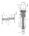
- Fig. 5 shows a particularly advantageous one-pipe embodiment of an exhaust assembly 81 according to the invention.
- the exhaust assembly 81 comprises one exhaust 84 that is directly connectable to the feed pipe 82, which exhaust comprises a housing 91 and a perforated tube 83 centrally arranged therein and extending in the longitudinal direction, which tube, in assembled condition, has one side connecting to the feed pipe 82 and has the other side opening into an exhaust piece 85.
- a valve 89 is provided in the tube 83, which valve in a first position closes the free passage of the tube 83 and in a second position substantially releases it.
- the tube 83 is surrounded with space by the housing 91, which, adjacent the feed pipe 82, closes tightly around the tube 83 and is in flow connection with the exhaust piece 85, around and downstream of the tube 83.
- the valve 89 is in the above-described manner operable, through servo control, between the first and the second position.
- Adjacent the end located on the side of the exhaust piece 85 a number of for instance disk-shaped muffler elements 95 are provided around the tube 83, which muffler elements provide for noise adjustment and reduction and possibly power limitation when exhaust gases are guided therealong.
- An exhaust assembly 81 according to Fig. 5 can be used as follows.
- the exhaust assembly 81 is connected to a feed pipe 82 in such a manner that combustion gases of an engine can be guided into the perforated tube 83 via the feed pipe 82.
- the valve 89 is then moved into the second position, enabling the combustion gases to be discharged to the environment via the tube 83 and the exhaust piece 85 practically without any resistance.
- this flow is shown by the arrow V1. This involves the generation of a first, relatively loud "engine” noise.
- valve 89 When the valve 89 is controlled so as to be partly or completely closed, the back pressure in the tube 83 is increased, whereby a part of the or all combustion gases are forced between the tube 83 and the housing 91 via the perforation openings 94 in the inner tube 83. There, these gases are subsequently forced along the muffler elements 95 and discharged, via the exhaust piece 85, to the environment. Because of the flow path V2 via the perforations and the muffler elements, a change and reduction of noise and, possibly, a reduction of power is provided. Through a suitable selection of, inter alia, the muffler elements 95 and the laminations 96 around the valve 89, a particular maximum noise volume can be set at a closed valve 89, for instance 81 dB.
- Adjustment of the damping characteristic should at least be understood to mean adjustment of the noise level produced by or via the exhaust assembly and/or the back pressure provided for the engine by the exhaust assembly, both during the use of the exhaust assembly.
- An exhaust assembly according to the invention is in particular suitable for use with a motorbike, a moped or a motorcar. This may involve different assemblies being used side by side, for instance one per cylinder of the engine of the relevant vehicle, or in an integrated manner.
- three or more exhausts having different or comparable damping characteristics may be used, while switching means may be provided for switching on each of the exhausts separately or combinations thereof.
- different combinations of the features given in the specification and the claims are possible in manners speaking for themselves.
- Various other means for adjusting the damping characteristic of an exhaust assembly in a comparable manner may be used, depending on the type of exhaust opted for.
- the means for controlling the damping characteristic may be incorporated downstream of the first and any further mufflers (dampers) and a catalyst, if any, which saves costs and space.
Landscapes
- Engineering & Computer Science (AREA)
- Chemical & Material Sciences (AREA)
- Combustion & Propulsion (AREA)
- Mechanical Engineering (AREA)
- General Engineering & Computer Science (AREA)
- Exhaust Silencers (AREA)
- Processes For Solid Components From Exhaust (AREA)
- Exhaust-Gas Circulating Devices (AREA)
- Exhaust Gas After Treatment (AREA)
Claims (11)
- (A) Auspuffanordnung zur Verwendung mit einem Kraftfahrzeug mit Verbrennungsmotor,(B) wobei die Auspuffanordnung aufweist: eine Einrichtung zum Verbinden mit dem Verbrennungsmotor,(C) wenigstens einem Auspuff,(D) und wenigstens einem Schalldämpfer,(E) wobei Steuereinrichtungen zum Steuern der Dämpfungscharakteristik der Auspuffanordnung vorgesehen sind, und(F) wobei die Auspuffanordnung (1, 21, 41, 61, 81) wenigstens einen ersten Verbrennungsgasströmungsweg V1 und einen zweiten Verbrennungsgasströmungsweg V2 aufweist,(G) wobei die Steuereinrichtungen (3, 9, 10; 23, 29, 30; 50, 53, 56; 70, 75, 76, 77; 89) während der Verwendung der mit einem Verbrennungsmotor verbundenen Auspuffanordnung selektiv durch einen Bediener betätigbar sind,(H) und die Steuereinrichtungen in der Lage sind, einen von den Verbrennungsgasen des Motors erzeugten annähernd konstanten Strom ungeachtet des Volumens der Verbrennungsgase selektiv auf die Verbrennungsgasströmungswege (V1, V2) zu verteilen,(I) wobei wenigstens einer der Gasströmungswege eine Dämpfungseinrichtung aufweist, so daß(J) die Verbrennungsgasströmungswege (V1, V2) erheblich voneinander verschiedene Dämpfungscharakteristiken aufweisen.
- Auspuffanordnung nach Anspruch 1, dadurch gekennzeichnet, daß die Anordnung (1, 21) wenigstens zwei Auspuffe (4, 5; 24, 25) aufweist, die jeweils einen jeweiligen Verbrennungsgasströmungsweg (V1, V2) bilden, wobei die Steuereinrichtungen mindestens Schalteinrichtungen (3, 9; 23, 29) zwischen der Einrichtung zum Verbinden mit dem Verbrennungsmotor, (2, 22) und den Auspuffen (4, 5; 24, 25) aufweisen, wobei die Schalteinrichtung in der Lage ist, selektiv für wenigstens einen der Auspuffe (4, 5; 24, 25) eine Abgasverbindung herzustellen.
- Auspuffanordnung nach Anspruch 2, dadurch gekennzeichnet, daß die Steuereinrichtungen (3, 9, 10; 23, 29, 30; 50, 53, 56; 70, 75, 76, 77) einen Verteiler (3, 23) aufweisen, der auf einer Seite mit der Einrichtung zum Verbinden mit dem Verbrennungsmotor (2, 22) verbunden und auf der anderen Seite mit wenigstens zwei getrennten Verbindungseinrichtungen (7, 8; 27, 28) versehen ist, mit denen jeweils wenigstens ein Auspuff (4, 5; 24, 25) verbunden ist, wobei die Schalteinrichtungen eine Ventileinrichtung (9; 29) aufweisen, die sich in den Verteiler (3; 23) erstreckt, um wenigstens eine der Verbindungseinrichtungen (7, 8; 27, 28) wenigstens teilweise zu schließen oder freizugeben.
- Auspuffanordnung nach Anspruch 3, dadurch gekennzeichnet, daß der Verteiler (3; 23) wenigstens eine erste Verbindung zwischen der Einrichtung zum Verbinden mit dem Verbrennungsmotor (2, 22) und einem ersten Auspuff (4; 24) und eine zweite Verbindung zwischen der Einrichtung zum Verbinden mit dem Verbrennungsmotor (2, 22) und einem zweiten Auspuff (5; 25) bildet, wobei der Strömungswiderstand der ersten Verbindung geringer ist als der Strömungswiderstand der zweiten Verbindung, wobei die Ventileinrichtung (9; 29) derart ausgebildet ist, daß sie in der Lage ist, die erste Verbindung wenigstens im wesentlichen zu schließen.
- Auspuffanordnung nach Anspruch 4, dadurch gekennzeichnet, daß die erste Verbindung im wesentlichen gerade ist.
- Auspuffanordnung nach Anspruch 1, dadurch gekennzeichnet, daß die Steuereinrichtungen (3, 9, 10; 23, 29, 30; 50, 53, 56; 70, 75, 76, 77) eine Abdeckeinrichtung (53) aufweisen, die wenigstens einen Teils des oder jedes Schalldämpfers (52) für das Durchströmen von Abgasen selektiv und aktiv schließt, und zwar derart, daß durch das Betätigen der Abdeckeinrichtung (53) ein kleinerer oder ein größerer Teil des jeweiligen Schalldämpfers (52) während des Betriebs von Abgasen durchströmt wird.
- Auspuffanordnung nach Anspruch 6, dadurch gekennzeichnet, daß der oder jeder Schalldämpfer (52) eine langgestreckte Form aufweist, wobei die Abgase während des Betriebs von außen durch Durchlässe (54, 55) in den Schalldämpfer (52) und durch den Schalldämpfer zur Auslaßseite des Auspuffs (4) strömen, wobei die Abdeckeinrichtung ein auf den Schalldämpfer (52) aufschiebbares mantelförmiges Teil (53) zum Schließen wenigsten eines Teils der Durchlässe (54, 55) aufweist.
- Auspuffanordnung nach Anspruch 1, dadurch gekennzeichnet, daß der oder jeder Schalldämpfer (72) mehrere lamellenförmige Schalldämpferelemente (75) aufweist, die in Längsrichtung des Schalldämpfers hintereinander angeordnet sind, wobei die Abgase im Betrieb zwischen den Schalldämpferelementen (75) in Richtung der Auslaßseite des jeweiligen Auspuffs (74) strömen, wobei die Steuereinrichtungen (3, 9, 10; 23, 29, 30; 50, 53, 56; 70, 75, 76, 77) eine Schalteinrichtung (70, 77) aufweisen, um wenigstens einiger der Schalldämpferelemente (75) relativ zueinander in Längsrichtung des Schalldämpfers (72) derart zu bewegen, daß dadurch die Größe der Durchlässe zwischen den Schalldämpferelementen (75) eingestellt wird.
- Auspuffanordnung nach Anspruch 1, dadurch gekennzeichnet, daß die Auspuffanordnung ein gasdichtes Gehäuse (91) aufweist, das ein davon beabstandetes perforiertes Innenrohr (83) aufweist, wobei das Gehäuse auf einer Seite um das Innenrohr (83) geschlossen ist, welches Verbindungseinrichtungen für ein Verbrennungsgaszuleitungsrohr (82) aufweist, wobei, mit Abstand von den Verbindungseinrichtungen, eine Ventileinrichtung (89) zum vollständigen oder teilweisen Schließen des Innenrohres (83) vorgesehen ist, wobei die Anordnung derart ausgebildet ist, daß bei offener Ventileinrichtung (89) der erste Verbrennungsgasströmungsweg (V1) sich ohne Unterbrechung durch das Innenrohr (83) in die Umwelt erstreckt, um einen freien Strömungsweg zu bilden, während bei geschlossener Ventileinrichtung (89) der zweite Verbrennungsgasströmungsweg (V2) über das Innenrohr (83) und die darin ausgebildeten Perforationsöffnungen (83) zwischen dem Innenrohr (83) und dem Gehäuse (91) in die Umwelt verläuft.
- Anordnung nach einem der vorhergehenden Ansprüche, dadurch gekennzeichnet, daß die Steuereinrichtungen (3, 9, 10; 23, 29, 30; 50, 53, 56; 70, 75, 76, 77) vorzugsweise elektrisch oder hydraulisch fernsteuerbar sind.
- Fahrzeug mit einer Auspuffanordnung nach einem der Ansprüche 1-10.
Applications Claiming Priority (5)
| Application Number | Priority Date | Filing Date | Title |
|---|---|---|---|
| NL1002921 | 1996-04-22 | ||
| NL1002921A NL1002921C2 (nl) | 1996-04-22 | 1996-04-22 | Uitlaatsamenstel voor gebruik bij verbrandingsmotoren en voertuig, voorzien van een dergelijke samenstel. |
| US1612096P | 1996-04-24 | 1996-04-24 | |
| US16120P | 1996-04-24 | ||
| PCT/NL1997/000204 WO1997040264A1 (en) | 1996-04-22 | 1997-04-21 | Exhaust assembly for use with combustion engines, and vehicle provided with such assembly |
Publications (2)
| Publication Number | Publication Date |
|---|---|
| EP0895562A1 EP0895562A1 (de) | 1999-02-10 |
| EP0895562B1 true EP0895562B1 (de) | 2000-07-05 |
Family
ID=26642379
Family Applications (1)
| Application Number | Title | Priority Date | Filing Date |
|---|---|---|---|
| EP97917483A Expired - Lifetime EP0895562B1 (de) | 1996-04-22 | 1997-04-21 | Abgasvorrichtung für brennkraftmaschinen und fahrzeug mit dieser vorrichtung |
Country Status (5)
| Country | Link |
|---|---|
| US (1) | US6178745B1 (de) |
| EP (1) | EP0895562B1 (de) |
| AT (1) | ATE194410T1 (de) |
| DE (1) | DE69702447T2 (de) |
| WO (1) | WO1997040264A1 (de) |
Cited By (1)
| Publication number | Priority date | Publication date | Assignee | Title |
|---|---|---|---|---|
| DE102006044381B4 (de) * | 2005-09-23 | 2015-07-30 | Werner Müller | Abgasvorrichtung mit sekundärer Leistungs- bzw. Drehmomentsteuerung bzw. -regelung |
Families Citing this family (31)
| Publication number | Priority date | Publication date | Assignee | Title |
|---|---|---|---|---|
| DE10020491A1 (de) * | 2000-04-26 | 2002-03-14 | Eberspaecher J Gmbh & Co | Schalldämpferanlage eines Kraftfahrzeuges mit variabler Dämpfungscharakteristik |
| US6454047B1 (en) * | 2000-10-17 | 2002-09-24 | Bbnt Solutions Llc | System and method for phases noise attenuation |
| US6887439B2 (en) * | 2000-12-15 | 2005-05-03 | Delphi Technologies, Inc. | Variable flow regulator for use with catalytic converters |
| JP3901483B2 (ja) * | 2001-10-04 | 2007-04-04 | ヤマハ発動機株式会社 | エンジンの吸気音調整構造及び排気音調整構造 |
| US6901752B2 (en) * | 2002-02-06 | 2005-06-07 | Arvin Technologies, Inc. | Exhaust processor with variable tuning system and method of operating such exhaust processor |
| US6732510B2 (en) * | 2002-02-06 | 2004-05-11 | Arvin Technologies, Inc. | Exhaust processor with variable tuning system |
| DE10231056A1 (de) * | 2002-07-10 | 2004-02-05 | J. Eberspächer GmbH & Co. KG | Abgasanlage |
| US20040108162A1 (en) * | 2002-12-02 | 2004-06-10 | Gilles Couvrette | Sound level adjustable muffler |
| US20060249328A1 (en) * | 2002-12-26 | 2006-11-09 | Hiroyuki Ichikawa | Muffler for motor vehicle |
| WO2005026508A1 (en) * | 2003-09-12 | 2005-03-24 | Martin Lester Cunliffe | Exhaust muffler |
| KR200340730Y1 (ko) * | 2003-09-19 | 2004-02-11 | 유영배 | 자동차 머플러 |
| SE526680C2 (sv) * | 2003-12-31 | 2005-10-25 | Abb Ab | Förfarande för reduktion av buller i en högeffektförbränningsmotor |
| US7428947B2 (en) * | 2004-02-12 | 2008-09-30 | Emcon Technologies Llc | Electrically controlled in-muffler exhaust valve for use during cylinder deactivation |
| US20080023261A1 (en) * | 2004-05-14 | 2008-01-31 | Yanmar Co., Ltd. | Noise Proof Structure of Cabin |
| US7117974B2 (en) * | 2004-05-14 | 2006-10-10 | Visteon Global Technologies, Inc. | Electronically controlled dual chamber variable resonator |
| US7347045B2 (en) * | 2004-06-30 | 2008-03-25 | Harley-Davidson Motor Company Group, Inc. | Motorcycle dynamic exhaust system |
| WO2007016767A1 (en) * | 2005-08-05 | 2007-02-15 | Rowe Grant M | Variable sound muffler system |
| US7575096B2 (en) * | 2005-09-21 | 2009-08-18 | Emcon Technologies Llc | Pressed assembly for passive valve installation |
| US20070074507A1 (en) * | 2005-09-23 | 2007-04-05 | Werner Muller | Exhaust system with secondary performance respective torque control/regulation |
| US7673720B2 (en) * | 2006-03-02 | 2010-03-09 | Pacbrake Company | High-performance muffler assembly with multiple modes of operation |
| US20100307864A1 (en) * | 2009-06-09 | 2010-12-09 | Bohata John F | Automotive muffler having means for switching between loud and quieter modes |
| DE202010012100U1 (de) | 2010-09-02 | 2011-02-10 | The Jekill & Hyde Company B.V. | Auspuff, Klappengehäuse und motorisiertes Fahrzeug |
| WO2012030222A1 (en) | 2010-09-02 | 2012-03-08 | The Jekill & Hyde Company B.V. | Exhaust, valve housing, motorized vehicle, and method of mounting |
| DE102010064088A1 (de) | 2010-12-02 | 2012-06-06 | Kess-Tech Gmbh | Schalldämpfer für Auspuff-Anlagen |
| DE202011001554U1 (de) | 2011-01-14 | 2011-04-14 | Jekill & Hyde Company B.V. | Auspuffanordnung zur Verwendung mit einem Verbrennungsmotor |
| DE102011088150A1 (de) * | 2011-12-09 | 2013-06-13 | Kess-Tech Gmbh | Schalldämpfer-Anordnung |
| DE202012002948U1 (de) | 2012-03-23 | 2012-04-03 | The Jekill & Hyde Company Bv | Auspuffanordnung zur Verwendung mit einem Verbrennungsmotor |
| US10443479B2 (en) | 2014-10-30 | 2019-10-15 | Roush Enterprises, Inc. | Exhaust control system |
| WO2017079156A1 (en) | 2015-11-02 | 2017-05-11 | Roush Enterprises, Inc. | Muffler with selected exhaust pathways |
| US20180223709A1 (en) * | 2017-02-06 | 2018-08-09 | GM Global Technology Operations LLC | Function based continuous exhaust valve control |
| US10823023B2 (en) * | 2017-12-27 | 2020-11-03 | Randy Phelps | Selective acoustic soundproofing device |
Family Cites Families (16)
| Publication number | Priority date | Publication date | Assignee | Title |
|---|---|---|---|---|
| US951770A (en) * | 1909-07-29 | 1910-03-08 | James M Miller | Silencer. |
| US981584A (en) * | 1910-10-15 | 1911-01-10 | James Madison Miller | Silencer. |
| US1591088A (en) | 1920-04-29 | 1926-07-06 | William H Holmes | Hydrocarbon motor |
| FR764504A (fr) | 1933-02-10 | 1934-05-23 | Silencieux, notamment pour moteurs, véhicules et armes à feu | |
| US2072372A (en) | 1934-02-23 | 1937-03-02 | Riethmiller Ruth | Exhaust system for automotive engines |
| GB446914A (en) * | 1934-11-09 | 1936-05-08 | Alan Arnold Griffith | Improvements in or relating to the exhaust systems of internal combustion engines |
| US2382159A (en) * | 1942-10-16 | 1945-08-14 | Harry A R Klemm | Muffler |
| BE526045A (de) * | 1953-02-02 | |||
| US3042138A (en) * | 1961-02-07 | 1962-07-03 | Reinert Richard | Exhaust muffler |
| US3141519A (en) * | 1962-09-10 | 1964-07-21 | Edward W Bottum | Adjustable muffler |
| DE2514689A1 (de) | 1975-04-04 | 1976-10-14 | Moos Guenter Ing Grad | Vorrichtung zur minderung von durch pulsierend stroemende gase hervorgerufenen geraeuschen |
| US4913260A (en) * | 1988-01-11 | 1990-04-03 | Tenneco Inc. | Gas silencing system with controlling sound attenuation |
| JPH0788770B2 (ja) | 1988-01-16 | 1995-09-27 | 日産自動車株式会社 | 自動車の排気消音装置 |
| JP2689720B2 (ja) * | 1990-11-06 | 1997-12-10 | 日産自動車株式会社 | 制御型マフラ |
| JP3443187B2 (ja) * | 1994-11-04 | 2003-09-02 | カルソニックカンセイ株式会社 | 制御型排気系システム |
| KR19980049083A (ko) * | 1996-12-19 | 1998-09-15 | 박병재 | 자동차용 소음기 |
-
1997
- 1997-04-21 DE DE69702447T patent/DE69702447T2/de not_active Expired - Lifetime
- 1997-04-21 US US09/171,571 patent/US6178745B1/en not_active Expired - Fee Related
- 1997-04-21 WO PCT/NL1997/000204 patent/WO1997040264A1/en active IP Right Grant
- 1997-04-21 AT AT97917483T patent/ATE194410T1/de not_active IP Right Cessation
- 1997-04-21 EP EP97917483A patent/EP0895562B1/de not_active Expired - Lifetime
Cited By (1)
| Publication number | Priority date | Publication date | Assignee | Title |
|---|---|---|---|---|
| DE102006044381B4 (de) * | 2005-09-23 | 2015-07-30 | Werner Müller | Abgasvorrichtung mit sekundärer Leistungs- bzw. Drehmomentsteuerung bzw. -regelung |
Also Published As
| Publication number | Publication date |
|---|---|
| ATE194410T1 (de) | 2000-07-15 |
| US6178745B1 (en) | 2001-01-30 |
| EP0895562A1 (de) | 1999-02-10 |
| DE69702447T2 (de) | 2001-02-22 |
| WO1997040264A1 (en) | 1997-10-30 |
| DE69702447D1 (de) | 2000-08-10 |
Similar Documents
| Publication | Publication Date | Title |
|---|---|---|
| EP0895562B1 (de) | Abgasvorrichtung für brennkraftmaschinen und fahrzeug mit dieser vorrichtung | |
| US7040451B2 (en) | Automotive exhaust silencer system with variable damping characteristics | |
| EP1400665A1 (de) | Abgasentgiftungsvorrichtung | |
| JP2004278519A (ja) | 可変減衰特性を有するマフラー | |
| GB2146070A (en) | I C engine air intake silencing | |
| JPH08232651A (ja) | 内燃エンジンの排気システム内の空気噴射回路のための閉止バルブユニット | |
| DE102006044381B4 (de) | Abgasvorrichtung mit sekundärer Leistungs- bzw. Drehmomentsteuerung bzw. -regelung | |
| EP1201897A3 (de) | Steuereinheit und Verfahren zur Berechnung des Luftdurchflusses | |
| CA2449392A1 (en) | Sound level adjustable muffler | |
| US20160305347A1 (en) | Control valve for an exhaust system and an exhaust system having such a control valve | |
| CN101395356B (zh) | 增压系统 | |
| JP4157008B2 (ja) | 車両用吸気構造 | |
| NL1002921C2 (nl) | Uitlaatsamenstel voor gebruik bij verbrandingsmotoren en voertuig, voorzien van een dergelijke samenstel. | |
| US1658766A (en) | Conduit construction | |
| JP3920645B2 (ja) | エンジン用マフラ | |
| US20070074507A1 (en) | Exhaust system with secondary performance respective torque control/regulation | |
| TW451027B (en) | Intake air temperature control method and device | |
| JP2005201204A (ja) | 内燃機関の吸気系構造 | |
| JP2004225643A (ja) | 電気制御式自動車用マフラー装置 | |
| US20040163886A1 (en) | Air turbine for combustion engine | |
| US20170067380A1 (en) | Exhaust Assembly | |
| US20070095606A1 (en) | Internal combustion engine exhaust line muffler | |
| GB2313409A (en) | Adjustable exhaust silencer for vehicles | |
| JPS58182025A (ja) | 燃焼器 | |
| JPH0612767Y2 (ja) | エアーポンプの消音装置 |
Legal Events
| Date | Code | Title | Description |
|---|---|---|---|
| PUAI | Public reference made under article 153(3) epc to a published international application that has entered the european phase |
Free format text: ORIGINAL CODE: 0009012 |
|
| 17P | Request for examination filed |
Effective date: 19981021 |
|
| AK | Designated contracting states |
Kind code of ref document: A1 Designated state(s): AT BE CH DE FR GB IT LI NL SE |
|
| GRAG | Despatch of communication of intention to grant |
Free format text: ORIGINAL CODE: EPIDOS AGRA |
|
| 17Q | First examination report despatched |
Effective date: 19990222 |
|
| GRAG | Despatch of communication of intention to grant |
Free format text: ORIGINAL CODE: EPIDOS AGRA |
|
| GRAH | Despatch of communication of intention to grant a patent |
Free format text: ORIGINAL CODE: EPIDOS IGRA |
|
| GRAH | Despatch of communication of intention to grant a patent |
Free format text: ORIGINAL CODE: EPIDOS IGRA |
|
| GRAA | (expected) grant |
Free format text: ORIGINAL CODE: 0009210 |
|
| AK | Designated contracting states |
Kind code of ref document: B1 Designated state(s): AT BE CH DE FR GB IT LI NL SE |
|
| PG25 | Lapsed in a contracting state [announced via postgrant information from national office to epo] |
Ref country code: IT Free format text: LAPSE BECAUSE OF FAILURE TO SUBMIT A TRANSLATION OF THE DESCRIPTION OR TO PAY THE FEE WITHIN THE PRE;WARNING: LAPSES OF ITALIAN PATENTS WITH EFFECTIVE DATE BEFORE 2007 MAY HAVE OCCURRED AT ANY TIME BEFORE 2007. THE CORRECT EFFECTIVE DATE MAY BE DIFFERENT FROM THE ONE RECORDED.SCRIBED TIME-LIMIT Effective date: 20000705 Ref country code: FR Free format text: LAPSE BECAUSE OF FAILURE TO SUBMIT A TRANSLATION OF THE DESCRIPTION OR TO PAY THE FEE WITHIN THE PRESCRIBED TIME-LIMIT Effective date: 20000705 |
|
| REF | Corresponds to: |
Ref document number: 194410 Country of ref document: AT Date of ref document: 20000715 Kind code of ref document: T |
|
| REG | Reference to a national code |
Ref country code: CH Ref legal event code: EP |
|
| REF | Corresponds to: |
Ref document number: 69702447 Country of ref document: DE Date of ref document: 20000810 |
|
| PG25 | Lapsed in a contracting state [announced via postgrant information from national office to epo] |
Ref country code: SE Free format text: LAPSE BECAUSE OF FAILURE TO SUBMIT A TRANSLATION OF THE DESCRIPTION OR TO PAY THE FEE WITHIN THE PRESCRIBED TIME-LIMIT Effective date: 20001005 |
|
| REG | Reference to a national code |
Ref country code: CH Ref legal event code: NV Representative=s name: E. BLUM & CO. PATENTANWAELTE |
|
| EN | Fr: translation not filed | ||
| PLBE | No opposition filed within time limit |
Free format text: ORIGINAL CODE: 0009261 |
|
| STAA | Information on the status of an ep patent application or granted ep patent |
Free format text: STATUS: NO OPPOSITION FILED WITHIN TIME LIMIT |
|
| 26N | No opposition filed | ||
| REG | Reference to a national code |
Ref country code: GB Ref legal event code: IF02 |
|
| REG | Reference to a national code |
Ref country code: CH Ref legal event code: PFA Owner name: MEUSEN, WILHELMUS LAMBERTUS ARNOLDUS Free format text: MEUSEN, WILHELMUS LAMBERTUS ARNOLDUS#PASTOOR VRANCKENLAAN 49#5953 CN REUVER (NL) -TRANSFER TO- MEUSEN, WILHELMUS LAMBERTUS ARNOLDUS#PASTOOR VRANCKENLAAN 49#5953 CN REUVER (NL) |
|
| PGFP | Annual fee paid to national office [announced via postgrant information from national office to epo] |
Ref country code: NL Payment date: 20100415 Year of fee payment: 14 Ref country code: DE Payment date: 20100423 Year of fee payment: 14 Ref country code: AT Payment date: 20100415 Year of fee payment: 14 |
|
| PGFP | Annual fee paid to national office [announced via postgrant information from national office to epo] |
Ref country code: CH Payment date: 20100423 Year of fee payment: 14 Ref country code: BE Payment date: 20100419 Year of fee payment: 14 |
|
| REG | Reference to a national code |
Ref country code: CH Ref legal event code: PUE Owner name: THE JEKILL & HYDE COMPANY B.V. Free format text: MEUSEN, WILHELMUS LAMBERTUS ARNOLDUS#PASTOOR VRANCKENLAAN 49#5953 CN REUVER (NL) -TRANSFER TO- THE JEKILL & HYDE COMPANY B.V.#PANNENBERG 32#5951DM BELFELD (NL) |
|
| REG | Reference to a national code |
Ref country code: NL Ref legal event code: SD Effective date: 20101101 |
|
| PGFP | Annual fee paid to national office [announced via postgrant information from national office to epo] |
Ref country code: GB Payment date: 20100420 Year of fee payment: 14 |
|
| REG | Reference to a national code |
Ref country code: GB Ref legal event code: 732E Free format text: REGISTERED BETWEEN 20101111 AND 20101117 |
|
| BERE | Be: lapsed |
Owner name: THE JEKILL & HYDE CY B.V. Effective date: 20110430 |
|
| REG | Reference to a national code |
Ref country code: DE Ref legal event code: R119 Ref document number: 69702447 Country of ref document: DE |
|
| REG | Reference to a national code |
Ref country code: NL Ref legal event code: V1 Effective date: 20111101 |
|
| REG | Reference to a national code |
Ref country code: CH Ref legal event code: PL |
|
| GBPC | Gb: european patent ceased through non-payment of renewal fee |
Effective date: 20110421 |
|
| REG | Reference to a national code |
Ref country code: AT Ref legal event code: MM01 Ref document number: 194410 Country of ref document: AT Kind code of ref document: T Effective date: 20110421 |
|
| PG25 | Lapsed in a contracting state [announced via postgrant information from national office to epo] |
Ref country code: LI Free format text: LAPSE BECAUSE OF NON-PAYMENT OF DUE FEES Effective date: 20110430 Ref country code: CH Free format text: LAPSE BECAUSE OF NON-PAYMENT OF DUE FEES Effective date: 20110430 Ref country code: NL Free format text: LAPSE BECAUSE OF NON-PAYMENT OF DUE FEES Effective date: 20111101 Ref country code: BE Free format text: LAPSE BECAUSE OF NON-PAYMENT OF DUE FEES Effective date: 20110430 |
|
| PG25 | Lapsed in a contracting state [announced via postgrant information from national office to epo] |
Ref country code: GB Free format text: LAPSE BECAUSE OF NON-PAYMENT OF DUE FEES Effective date: 20110421 Ref country code: AT Free format text: LAPSE BECAUSE OF NON-PAYMENT OF DUE FEES Effective date: 20110421 |
|
| PG25 | Lapsed in a contracting state [announced via postgrant information from national office to epo] |
Ref country code: DE Free format text: LAPSE BECAUSE OF NON-PAYMENT OF DUE FEES Effective date: 20111031 |
|
| REG | Reference to a national code |
Ref country code: DE Ref legal event code: R119 Ref document number: 69702447 Country of ref document: DE Effective date: 20111101 Ref country code: DE Ref legal event code: R119 Ref document number: 69702447 Country of ref document: DE Effective date: 20111031 |