EP0895374B1 - Système de communication pour un réseau informatique - Google Patents
Système de communication pour un réseau informatique Download PDFInfo
- Publication number
- EP0895374B1 EP0895374B1 EP98301849A EP98301849A EP0895374B1 EP 0895374 B1 EP0895374 B1 EP 0895374B1 EP 98301849 A EP98301849 A EP 98301849A EP 98301849 A EP98301849 A EP 98301849A EP 0895374 B1 EP0895374 B1 EP 0895374B1
- Authority
- EP
- European Patent Office
- Prior art keywords
- agent
- gateway
- terminal
- computer network
- network
- Prior art date
- Legal status (The legal status is an assumption and is not a legal conclusion. Google has not performed a legal analysis and makes no representation as to the accuracy of the status listed.)
- Expired - Lifetime
Links
Images


Classifications
-
- H—ELECTRICITY
- H04—ELECTRIC COMMUNICATION TECHNIQUE
- H04N—PICTORIAL COMMUNICATION, e.g. TELEVISION
- H04N21/00—Selective content distribution, e.g. interactive television or video on demand [VOD]
- H04N21/60—Network structure or processes for video distribution between server and client or between remote clients; Control signalling between clients, server and network components; Transmission of management data between server and client, e.g. sending from server to client commands for recording incoming content stream; Communication details between server and client
- H04N21/63—Control signaling related to video distribution between client, server and network components; Network processes for video distribution between server and clients or between remote clients, e.g. transmitting basic layer and enhancement layers over different transmission paths, setting up a peer-to-peer communication via Internet between remote STB's; Communication protocols; Addressing
- H04N21/643—Communication protocols
-
- H—ELECTRICITY
- H04—ELECTRIC COMMUNICATION TECHNIQUE
- H04L—TRANSMISSION OF DIGITAL INFORMATION, e.g. TELEGRAPHIC COMMUNICATION
- H04L41/00—Arrangements for maintenance, administration or management of data switching networks, e.g. of packet switching networks
- H04L41/04—Network management architectures or arrangements
- H04L41/046—Network management architectures or arrangements comprising network management agents or mobile agents therefor
-
- H—ELECTRICITY
- H04—ELECTRIC COMMUNICATION TECHNIQUE
- H04L—TRANSMISSION OF DIGITAL INFORMATION, e.g. TELEGRAPHIC COMMUNICATION
- H04L43/00—Arrangements for monitoring or testing data switching networks
Definitions
- the present invention relates to the control of data communication based on a distributed control system in a computer network wherein various sorts of networks and terminals are connected.
- the Internet has been chiefly made up of comparatively uniform networks (in other words, networks whose properties such as transmission rates are substantially the same).
- a private LAN in an enterprise or a university has employed Ethernet cable of 10 MHz, and individual organizations have been coupled by dedicated lines of 1 MHz or so.
- networks of comparatively narrow bandwidths based on radio systems or the dial-up PPP (Point-to-Point Protocol) have increased in addition to the private LANs.
- the radio networks differ from the conventional networks, not only in the narrow bandwidths, but also in mobile serviceabilities.
- desktop type terminals have hitherto formed the mainstream, personal computers of notebook type (Laptop type) and portable terminals being still smaller in size and lighter in weight have recently come into wide use.
- the prior art has the problem that, when a narrow-band network such as radio network is used, a long communicating time period is required for sending out data of comparatively large size such as image data. Another problem is that, when the portable terminal or the like is used, a received image cannot be entirely displayed. Still another problem is that, since the uniform networks are assumed, wasteful data which cannot be displayed are caused to flow through the networks in large quantities.
- the prior art has the problem that, in a network using a radio system, the line utilization factor of the network worsens, so the frequency resources thereof are wasted.
- ITU-T Recommendation H.323 (XP 002227146) November 1996, discloses a system, a terminal, and a gateway according to the preamble of each independent claim.
- US-A-5 638 494 discloses an adaptive communication system using process agents, which receive goals and invoke a process to achieve the goals, and device agents, each in communication with its own device.
- the system interconnects all the agents and carries goals between them, so that device agents operate their respective devices in response to receiving goals from a process agent.
- US-A-5 561 769 discloses a method and apparatus for executing a. distributed algorithm or server in a SNMPv1-based computer network, which involve encapsulating the algorithm or server with the SNMPv1 protocol.
- a communication system for a computer network having different networks comprising:
- a terminal for use in a communication system for a computer network having different networks linked by gateways comprising:
- a gateway for linking different networks in a computer network having a plurality of terminals comprising:
- Embodiments of the present invention may provide in a computer network, a communication control system of distributed control type in which data to be transmitted are adaptively varied in consideration of the transmission characteristics of individual networks and the processing capabilities of reception terminals.
- the plurality of agent units are distributed and cooperate, whereby the respective agent unit senses the situations of the terminal unit and the computer network, as well as the changes thereof.
- the gateway unit coupling the different networks controls (processes or/and accumulates) the communication data, for example, the multimedia contents of the WWW (World Wide Web) so as to execute data transfer in accordance with the situations of the terminal unit and the computer network, as well as the changes of these situations.
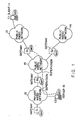
- Fig. 1 is a diagram for explaining a method of sensing the situations of a terminal and a network in a computer network which is useful for understanding the present invention.
- the computer network illustrated in Fig. 1 has an architecture in which a private wired network 12, a public wired network 15, and public radio networks 13 and 14 are interconnected through gateways G3, G1 and G2.
- the private wired network 12 is a LAN or the like which is installed in an enterprise, a university or the like.
- a server 10 which offers information such as WWW content , is connected to the private wired network 12.
- the terminal C1 of a client 11 who wishes to access the server 10 and to acquire the information is assumed in Fig. 1 to be connected to the public radio network 13 through a radio channel.
- the client 11 owns a portable terminal or the like and performs data communication by the use of, e. g., the channel of the portable telephone.
- the terminal of the client 11 may be a desktop type personal computer installed in a specified place, where the personal computer is connected to the public wired network 15 through a telephone line or the like.
- the gateways G1, G2 and G3 interconnect the public wired network 15, public radio networks 13 and 14, and private wired network 12 which differ in properties such as transmission rates and in communication protocols etc.
- each of the gateways G1, G2 and G3 forms a data communication interface from one network to another.
- the private wired network 12 can also be arranged so as to be connected to a gateway Gi and then to an unshown network, which shall not be explained more.
- agents facilities (or programs) for mutual information exchanges, called “agents”, are run beforehand in the terminals (the respective terminals C1 and C2 of the client 11 and the server 10) and the gateways G1, G2, G3 and Gi.
- the agents are constructed so as to fulfill different functions, depending upon the respective operating environments of the server 10, client 11, and gateways G1, G2, G3 and Gi.
- Information items such as the bandwidths of the networks to which the gateways G1, G2, G3 and Gi are connected, are prestored in the respective agents which are run in these gateways.
- the respective agents of the gateways G1, G2, G3 and Gi dynamically sense the current situations (such as the bandwidths) of the networks by means of, e.
- the gateways G1, G2 and G3 exchange dummy packets or the like with one another, thereby to acquire the information items, such as bandwidths, of the public wired network 15.
- the agents which are run in the terminals report the properties of these terminals (such as the sizes of displayable screens), the priority levels of the client user in the use of resources, and whether or not these terminals are connected to the associated networks, to the agents of the corresponding gateways G1 and G3.
- the agent operating in the terminal C1 of the client 11 transmits the information on this terminal C1 to the agent of the gateway G1.
- the agent operating in the terminal C2 of the server 10 transmits the information on this terminal C2 to the agent of the gateway G3.
- the above information items are exchanged between the agents of the gateways G1 and G3, so that the respective agents of the gateways G1 and G3 which exist in a path extending from the terminal C1 of the client 11 to the terminal C2 of the server 10 can obtain the information items on the terminals C2 and C1.
- the agents of the gateways G1 and G3 can know the types of the two terminals C1 and C2 (the properties thereof), the sorts of the networks through which these terminals communicate, and so forth
- the advantage of this arrangement is that the information items of the terminals, the resource priority levels of the user (client 11) and the situations of the networks, which cannot be found by the schemes of present-day computer networks, can be found to realize the communication of data in which such factors are taken into consideration.
- an image converting function is performed in a certain gateway (G1 or G3).
- the expression "image converting function” here signifies the conversion to image data conformed to the size of the display screen of the terminal.
- the image converting function of the gateway (G1 or G3) may be based on any known technique. In case of scaling down an image, the function executes such a process as thinning out pixels in accordance with a predetermined method.
- the part of the image to be transmitted is set by a predetermined method, and an image of predetermined size is thereafter extracted from the original image in the light of the information on the display screen of the terminal, so as to transmit the extracted image.
- the scale-down of the image when the scale-down of the image has been chosen, it is implemented by the image converting function of the gateway (G1 or G3), and the image of the 320 ⁇ 240 pixels is sent to the terminal.
- This contrivance is effective in the display of the terminal.
- the amount of data becomes smaller than that of the original image data after the image conversion, so that the volume of traffic on a path which extends from the gateway (G1 or G3) having the image converting function, to the client 11, can be sharply reduced.
- the resource priority levels of the user (client 11) can be implemented in such a way that (a) the scale-down or (b) the partial display in the image conversion is prestored in the agent of the terminal C1 of the user (client 11). Besides, whether a data-transfer time period or an image quality is preferable may be prestored, too. In this case, in the gateway G1 or G3, the data-transfer time period is calculated on the basis of the image data and the actual transfer rates of the networks 12, 15 and 13, and it is judged if the calculated time period satisfies a condition designated by the user (client 11).
- Sensing the situation of the network (the whole network which includes the private wired network 12, public wired network 15 and public radio network 13 and the gateway G1 or G3) is effective for the communication reflecting the situation of the network as explained in relation to the resource priority levels of the user.
- dynamic sensing in which the agents communicate with each other at predetermined time intervals, thereby to continually supervise the states of the networks
- the network whose properties change rapidly, such as a radio network.
- Fig. 2 is a diagram for explaining another computer network useful for understanding the present invention, the computer network being such that multimedia data (animation, voice, etc.) are transferred between a server and a client.
- multimedia data animation, voice, etc.
- the architecture of the computer network shown in Fig. 2 is basically the same as in Fig. 1, and is different in that a terminal C2 is the WWW server 20 generating the multimedia data.
- the other constituents which are the same as in Fig. 1 are denoted by the same reference numerals or symbols.
- the terminal C2 be the WWW server 20, while a terminal C1 be of the client 11.
- data are passed through three different networks (a private wired network 12, a public wired network 15 and a public radio network 13) and are passed through two gateways G1 and G3 meantime.
- the function of deleting wasteful communication data is provided in the gateway (G1 or G3).
- the expression "wasteful communication data” signifies image data etc. which are not normally displayed on the terminal C1 even when transferred, on account of the conditions of the transferring capabilities of the networks, the processing capability of the terminal C1 of the client 11, etc. as explained in conjunction with Fig. 1. Deleting the wasteful communication data corresponds to the execution of such a process as thinning out pixels in an image which is not normally displayed.
- the gateway In this system, data are cached in the gateway (G1 or G3). More specifically, the gateway (G1 or G3) has a memory for temporarily accumulating the data sent from the WWW server 20.
- the data caching is such a function that, in a case where a data request made by the client 11 agrees with a request made within a predetermined term in the past, the data accumulated in the memory are delivered to the client 11 without sending any new request to the WWW server 20.
- this caching function is usually arranged in the gateway G1 by reason that useless communication can be reduced more as the function is nearer to the client 11.
- the terminals of many clients are really connected to the computer network, and gateways nearest to the terminals of the clients are caused to cache data for these client terminals. It is necessary therefor to grasp the architecture of the whole network, and this is implemented by an agent manager to be stated later.
- the image converting function as stated before is installed in the gateway G1 or G3.
- the image converting function is installed in the gateway G3 which is nearest to the WWW server 20. Thus, unnecessary data are prevented from flowing between the gateway G3 and the terminal C1 of the client 11.
- the data converting function should optimally be run in the gateway G3 from the viewpoint of reducing unnecessary traffic.
- the data converting function of the gateway G3 needs to know the bandwidth of the public radio network 13. Therefore, the agents of the gateways included in the communication path are endowed with the functions of reporting the information items of the associated networks to each other. Thus, the information items of the networks can be effectively utilized.
- Fig. 3 is a diagram for explaining a computer network which embodies the present invention, used in a case where the terminal of a client roams.
- the architecture of the computer network is similar to that of the computer network in each of Fig. 1 and Fig. 2. That is, the computer network in this embodiment includes a private wired network 12, a public wired network 15, public radio networks 13 and 14, gateways G1, G2 and G3 for connecting these networks, and a gateway Gi.
- the same constituents as in Fig. 1 or Fig. 2 bear the same reference numerals or symbols.
- the agent of the gateway G1 is communicating with an agent run in the terminal C1 of the client 11, thereby to acquire the information items of the processing speed of the terminal C1, the allowable data-transfer speed thereof, and so forth. Since, however, the terminal C1 is a portable terminal or the like using a radio channel, the network to which it is connected might change from the public radio network 13 to the public radio network 14 with the movement of the client 11 (user).
- the network path between the two terminals changes.
- the function (the agent itself) having operated in the gateway G1 or the properties retained in the gateway G1 are moved to the gateway G2.
- the communicating functions of the terminals C1 and C2 and the gateways G1 - G3 are controlled by the agents installed in the respective constituents.
- each of the agents is encapsulated so as to install the capsule in the corresponding terminal or gateway. In this way, the agent itself can be moved through a communication path.
- an error control method is adaptively altered in accordance with whether the data transfer quality of the transmission line of a network leading to the client is good or bad.
- an intermediate transmission line is a wired channel
- it is generally judged to have the good data quality, and hence, only a retransmission control is applied with a packet size held larger.
- a radio channel is included midway, it is judged to have a poor data quality, and hence, an intense error correction is applied with the packet size made smaller, whereupon the retransmission control is performed.
- Figs. 4A and 4B are diagrams for explaining the encapsulation of the facilities of an agent etc. and distributed object environments where the agent etc. operate, in which Fig. 4A illustrates an embodiment of the present invention.
- Fig. 4A illustrates the concept of the encapsulation.
- a program module 41 contains programs for the processes which are executed by the agent themselves as already described above. Only the program module 41 may exist in a case where it is installed in the terminal or the gateway and lies in an operable state.
- a program operation environment 42 for the operation of the program module 41 is put together with this program module 41 and is constructed as one object beforehand.
- the program operation environment 42 is first started to set the environment where the program module 41 can operate.
- a capsule 40 in which the program module 41 is combined with the program operation environment 42 as stated above, is used as a transfer unit. Accordingly, even in a case where the destination of transfer does not have the operating environment of the program module 41, the environment where the program module 41 is operable can be set by running the capsule 40 so as to start this program module 41.
- the "encapsulation of functions” signifies that a certain function is combined with an environment for the operation of the program so as to operate even solely.
- a "telescript” by way of example, a program counter, a stack pointer, etc. are put together with a program. Such a contrivance is necessitated especially for moving the program which is operating.
- Fig. 4B illustrates a case where the distributed object environments are installed in the computer network (not in accordance with the invention).
- Fig. 5 is a block diagram showing the common constructions of a gateway, a client and a server each of which includes an agent for incarnating the function of controlling communication data, and the construction of an agent manager which controls such agents. (In the ensuing description down to Fig. 10, the terminal of the client shall be expressed merely as the "client".)
- the functions of controlling the communication data in the terminals (the terminal of the client 11, and the terminals of the servers 10 and 20) and the gateways G1, G2 and G3 in the first to third embodiments are incarnated as encapsulated agent programs.
- the agents are managed by, for example, the agent manager 51 which exists in one server disposed in the computer network.
- the gateway, client or server 50 is constituted by agent reception unit 52, agent check unit 53, an agent platform 55 and an OS (operating system) 56.
- the agent reception unit 52 is unit for receiving the agent 59 which is transmitted from the agent manager 51.
- the agent 59 received by the agent reception unit 52 is delivered to the agent check unit 53.
- the agent check unit 53 decides whether or not the transmitted agent 59 is proper (or legal). In the event that the agent 59 is improper (or illegal), it is discarded. In contrast, on condition that the agent 59 is proper, it is delivered to the agent platform 55 being the operating environment thereof and is run as the agent 54.
- the agent platform 55 is constructed so as to operate on the OS 56.
- the agent platform 55 may be an environment where a WWW browser operates.
- agent 58 is also sent to and run in the gateway, client or server 57.
- the agent manager 51 is installed in one server within the computer network as stated before.
- This agent manager 51 includes agent storage unit 61, in which the agents are stored.
- the locations of the agents are managed by an agent storage location management table 62.
- Operation unit 63 is comprised of discrimination unit 64 and search unit 65.
- the discrimination unit 64 judges the necessity of acquiring information on the structure of the network and requests the search unit 65 to search for the corresponding agent.
- the search unit 65 refers to the agent storage location management table 62 in order to know where the agent to be transmitted is stored within the agent storage unit 61.
- the discrimination unit 64 receives the result of the reference, and issues a transmission command to agent transmission unit 60. Then, the agent transmission unit 60 reads out the corresponding agent from the agent storage unit 61 and transmits this agent to, e. g., the gateway.
- the agents 54 and 58 When the agents 54 and 58 have been respectively installed in the gateway, client or server 50 and 57, they communicate with each other and acquire the information items on the networks.
- the acquired information items on the networks are transmitted to the agent manager 51 as a message, and are received by message transmission/reception unit 66.
- the message transmission/reception unit 66 extracts network information items from the received message and stores them in network information memory unit 67. Further, information items indicating the sites of the respective agents are extracted from the network information items, and they are logged in an agent site management table 68.
- the discrimination unit 64 fetches the network information from the network information memory unit 67, and it commands the agent transmission unit 60 to transmit the agent to the gateway, client or server requiring the agent anew.
- the agent manager 51 acquires information on the network structure from the network by using, for example, the SNMP (Simple Network Management Protocol). Subsequently, the agent manager 51 computes an appropriate one of the gateways and terminals (the terminals of the client and server) from the acquired network structure information, and it transmits the agent to the computed constituent. Alternatively, the agents may be kept resident in the terminals (of the server and client) and the gateways beforehand.
- SNMP Simple Network Management Protocol
- the transmitted agent acquires the network information, such as bandwidth, of the network to which the pertinent gateway or terminal (of the client or server) is connected.
- the agent transmits a dummy packet to the associated network and computes a time period since the time of the transmission till the time at which the dummy packet is received again, thereby to measure the transmission rate of the network.
- the agent of the client acquires the size and resolution of a terminal screen, resource priority levels, etc.
- the acquisition of the information items is performed by loading data from a setting file of predetermined format (a file in which necessary information items are recorded in a predetermined form).
- the agent of the server acquires information on, e. g., to which network the server is connected.
- the agents of the gateways, server and client notify the agent manager 51 of the corresponding network information items and their own sites. They also notify any other agent of the network information items and the sites in compliance with a request made -by the other agent.
- the agent manager 51 further operates to add, delete and move the agents on the basis of such network information.
- each of the gateways, server and client possesses the agent platform 55 and the agent reception unit 52, and the agent manager 51 delivers the agents to the pertinent ones of the gateways and terminals (of the server and client).
- each of the gateways, server and client may also include agent transmission unit.
- the agent platform 55 may well be a distributed object environment of, for example, CORBA (Common ORB Architecture), HORB, or Java RMI (Java Remote Method Invocation specification). In the distributed object environment, only part of the function module (method) can be delivered besides the transmission of the agent itself.
- information on the structure (topology) of the network is first acquired from the router (gateway) in the network.
- the router is acquired using the SNMP.
- the acquired information is combined with network information such as the bandwidth of a section extending between the gateways, the bandwidth being acquired by the agents which are arranged in these gateways.
- network information such as the bandwidth of a section extending between the gateways, the bandwidth being acquired by the agents which are arranged in these gateways.
- Fig. 6 shows an example of the format of the agent site management table 68.
- the agent manager 51 needs to manage the sites of individual agents for the purpose of adding, deleting and moving the agents in accordance with network information. It is the agent site management table 68 that is provided for the purpose.
- the identifier of each of the agents is expressed by a machine name, domain name and agent name, and it is managed by agent management No.
- the site of each agent is expressed by, for example, an IP address and the agent management No. Accordingly, the agent site management table 68 is formed of, for example, a table which converts the identifier of each agent into the (IP address + agent management No.).
- the identifiers of the agents each being composed of the (machine name + domain name + agent name) are entered in a column 70, while the sites each being composed of the (IP address + agent management No.) are entered in a column 71 in correspondence with the identifiers.
- the column 70 bears "machine1" as the machine name, "domain1” as the domain name and "agent1" as the agent name.
- the column 71 bears "123.234.56.78" as the IP address and "111" as the agent management No.
- Fig. 7 is a flowchart showing the process of the agent manager 51.
- the agent manager 51 operates to receive network information from the agents of the gateways, server and client, to discriminate the optimal arrangement place or function of the agent in accordance with the sites of the agents and the type of the terminal in the presence of any change, to search the agent storage unit 61 for the required agent and fetch this agent, and to deliver the fetched agent to the optimal place.
- the agent manager 51 when the agent manager 51 is started, it waits the reception of any message from any of the agents at step S10. When any message has been received, whether or not the content of the message is the network information is judged at step S11. In a case where the message content is not the network information, another process based on the message content is executed. Here, since the process is not directly pertinent to the embodiment, it shall be omitted from this description.
- step S12 In a case where the message content has been judged as the network information at step S11, whether or not the network information has undergone any change is judged at step S12.
- the judgement on the change of the network information can be made in such a way that the network information received in the last cycle is stored in the network information memory unit 67, whereupon it is compared with the network information received anew.
- step S12 On condition that the absence of the change of the network information has been judged at step S12, the processing flow returns to step S10, at which the agent manager 51 waits the reception of any message. In contrast, on condition that the presence of the change of the network information has been judged at step S12, the processing flow advances to step S13, at which the optimal arrangement place or function of the agent is discriminated in accordance with the sites of the agents and the type of the terminal by the discrimination unit 64.
- the agent storage location management table 62 is searched for the agent by the search unit 65 at step S14.
- the agent is fetched from the agent storage unit 61 by the agent transmission unit 60.
- the agent is transmitted to the desired place by the agent transmission unit 60. Thereafter, the processing flow returns to step S10.
- Fig. 8 is a flowchart showing the process of the discrimination unit 64 included in the agent manager 51.
- the agent manager 51 receives the message from the agent by the message transmission/reception unit 66, and stores it in the network information memory unit 67.
- the discrimination unit 64 judges whether or not the network information stored in the network information memory unit 67 is of the client, at step S17. Subject to the client's network information, whether or not the client has roamed is judged at step S18. In a case where the client has not roamed, another process is executed. Here, since the other process is not directly pertinent to the embodiment, it shall be omitted from description.
- step S18 In a case where the roaming of the client has been judged at step S18, information on the network is fetched from the network information memory unit 67, and the gateway nearest to the place where the client lies currently is found (step S19). When the gateway nearest to the current place of the client has been found, whether or not the agent exists in this gateway is judged at step S20. The judgement is made by referring to the agent site management table 68.
- step S22 In the presence of the agent in the particular gateway, the processing flow advances to step S22.
- this agent stored in the agent storage unit 61 is transmitted to the particular gateway through the agent transmission unit 60 at step S21, whereupon the processing flow advances to step S22.
- step S22 a command is given for executing the data caching stated before by employing a memory not shown in Fig. 5. Thereafter, the processing flow returns to the step S17, at which the discrimination unit 64 stands by for the next processing.
- step S17 when it has been judged at step S17 that the agent having sent the message is not of the client, the processing flow advances to step S23, which serves to judge whether or not the message has been sent from the agent which is installed in the server transmitting an image.
- step S23 serves to judge whether or not the message has been sent from the agent which is installed in the server transmitting an image.
- another process corresponding to the content of the message is executed.
- the process since the process is not directly pertinent to the embodiment, it shall be omitted from description.
- step S23 the gateway nearest to the server is found in the same way as explained at step S19 (step S24). Subsequently, whether or not the agent exists in the found gateway is judged (step S25). In the presence of the agent in the particular gateway, the processing flow advances to step S27. On the other hand, in the absence of the agent in the particular gateway, this agent stored in the agent storage unit 61 is transmitted to the particular gateway through the agent transmission unit 60 at step S26, whereupon the processing flow advances to step S27.
- step S27 a command is given for activating (or starting) the image converting function which is installed in the gateway. Thereafter, the processing flow returns to step S17.
- the image converting function is a process which thins out pixels from image data or extracts only part of an image by utilizing any known technique.
- Fig. 9 is a flow chart for explaining an agent accepting process which is executed in each of the gateway, client and server 50.
- Fig. 9 The process illustrated in Fig. 9 is performed by the agent reception unit 52, agent check unit 53 and agent platform 55 which are shown in Fig. 5.
- the agent reception unit 52 receives the agent at step S28. Then, the received agent is temporarily stored at step S29. Subsequently, the agent check unit 53 checks the temporarily stored agent at step S30, and whether or not the agent is proper (or legal) is judged at step S31.
- This step S31 is executed to judge whether or not the agent is one for a communication control as sent from the agent manager 51 because what program is sent in as the agent, is not known. Without such processing, a virus etc. transmitted as the agent might be accepted. Therefore, the processing of step S31 is carried out.
- the agent check unit 53 deletes this agent at step S32, followed by step S28 at which the reception of the next agent is waited by the agent reception unit 52.
- this agent is activated (or started) under the operating environment of the agent platform 55 (step S33). Thereafter, the processing flow returns to step S28 so as to make ready for the reception of the next agent.
- Fig. 10 is a flow chart showing the flow of a process in which image data to be transmitted from the server to the client are converted by the gateway.
- the gateway when the gateway has known from the network information etc. that the terminal of the client is incapable of satisfactorily displaying the image data to-be-received, it transmits a menu for image conversion to the terminal of the client at step S34. Then, the gateway waits the reception of a choice menu item from the client at step S35.
- step S35 When the choice menu item has been received from the client at step S35, whether or not the content of the choice menu item is the partial display of an image is judged at step S36. On condition that the choice menu item is the partial display of the image, the flow advances to step S37, at which part of the image data is transmitted to the client. Then, the process is ended.
- step S38 On condition that the content of the choice menu item received at step S36 is not the partial display of the image, whether or not the content of the choice menu item is the scale-down display of the image is judged at step S38. Subject to the judgement that the content is not the scale-down display of the image, this content is decided to be an input which is not contained in the menu transmitted from the gateway, and a message which indicates the occurrence of an error in the menu item choice is transmitted to the client at step S46. Then, the flow returns to step S34 so as to the process from the transmission of the menu.
- the image is scaled down at step S39.
- the image scaling-down may be performed by a known technique, and the pixels of the image are thinned out in accordance with a predetermined method by way of example.
- a scaled-down image is subsequently transmitted to the client at step S40, whereupon the process is ended.
- step S41 On the side of the client, the reception of the menu from the gateway is first awaited (step S41). Subsequently, when the menu has been received, it is displayed, and the user of the client is prompted to choose a menu item (step S42). At step S43, the input of the choice menu item by the user is awaited, and the choice menu item is transmitted to the gateway when input.
- step S47 the reception of the message from the gateway is awaited . for a predetermined time period.
- step S48 serves to judge whether or not the choice error message has been received. Subject to the reception of the choice error message, the flow returns to step S41 so as to repeat the process from the beginning.
- step S48 The judgement at step S48 that the choice error message has not been received, signifies that the menu item choice has been successful.
- step S48 is therefore followed by step S44, at which the reception of the image data is awaited.
- step S45 the flow advances to step S45, at which the image is displayed.
- the menu of the image processing contains only the two menu items; the partial display of the image, and the scale-down display of the image.
- the monochromatic display of the image may well be added.
- the process is executed in the gateway which is-near to the terminal of the client.
- the first gateway near the terminal of the client receives the choice of the menu item from the client and transmits the menu item to the second gateway near the server, and the second gateway near the server executes the process such as image compression.
- the process such as image compression.
- Fig. 11 is a diagram for explaining another computer system to which the present invention may be applied, employing a virtual proxy server by which the client having roamed is treated as if he/she were accessing the same server.
- the terminal C1 of the client 11 is a mobile terminal.
- proxy server signifies a server (or gateway) to which the client 11 is connected in accessing a server 10 through a network.
- the virtual proxy server 81 is installed in order that an application such as the Web browser may designate this virtual proxy server 81.
- Gateways G1 - Gi find the optimal communication path between the two terminals C2 and C1 (of the server 10 and the client 11) on the basis of information items on these terminals and the situations of networks sensed, and the gateways transfer packets sent to the virtual proxy server 81, to an actual proxy server 82. Thus, even when the application does not know the roaming of the terminal C1, it selects the optimal proxy server 80 or 82 without altering its settings.
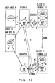
- Fig. 12 is a block diagram for explaining a system architecture which serves to implement the facility of the virtual proxy server.
- the terminal C1 of the client 11 first accesses the server 10 through a network 1.
- the terminal C1 of the client 11 includes a WWW browser 91, and a virtual proxy agent 92 which operates as a virtual proxy server.
- the virtual proxy agent 92 is an agent which has the same functions as those of an ordinary proxy server.
- the virtual proxy agent 92 serves to connect lines so that the terminal C1 of the client 11 may be permitted to communicate with a WWW server 96 through an access point (AP) 93, the network 1, and a proxy agent 94 installed in the actual gateway.
- AP access point
- the agent virtual proxy agent 92 having the same functions as those of the proxy server is installed in the terminal C1 of the client 11.
- the WWW server 96 can be accessed from the WWW browser 91 without being conscious of the fact that the proxy server has changed on account of the roaming of the client 11.
- the network to which the terminal C1 is connected has shifted from the network 1 to a network 2 on account of the roaming of the client 11. Then, the virtual proxy agent 92 installed in the terminal C1 of the client 11 detects the alteration of the access point from the AP 93 to an AP 97 and detects the alteration of a network structure.
- the virtual proxy agent 92 sends an inquiry about the structure of the network to the proxy agent 94 of the gateway G1 through the AP 97 as well as the network 2.
- the proxy agent 94 interrogates an agent manager 90 about the network information.
- the agent manager 90 possesses information items on the networks. Therefore, (3) the agent manager 90 transfers the network structure information to the proxy agent 94.
- the network structure information is sent from the proxy agent 94 to the virtual proxy agent 92 through the network 2 as well as the AP 97.
- the virtual proxy agent 92 judges whether or not the proxy server currently set (gateway G1) is optimal, by utilizing the functions as the proxy server.
- the gateway G1 is no longer the optimal proxy server. Therefore, (5) the virtual proxy agent 92 finds the optimal proxy server (gateway G2 having a proxy agent 98) and accesses the server 10 through this gateway G2.
- the proxy agents 94 and 98 indicate the functions of the respective gateways G1 and G2 being the proxy servers, as the agents.
- the virtual proxy agent 92 judges the gateway G2 to be the optimal proxy server, it utilizes the network structure information acquired from the agent manager 90 before.
- the mapping between access points (specified by telephone Nos. by way of example) and the optimal gateways (proxy servers) in the cases of accessing the server 10 by the use of the access points are prestored as a table or the like in the terminal C1 of the client 11.
- the optimal gateway may well be found in view of the stored table so as to connect the terminal C1 to this gateway.
- Fig. 13 is a flowchart showing the process of respective portions in the architecture which includes the virtual proxy server agent depicted in Fig. 12.
- the virtual proxy agent 92 on the side of the client 11 is first monitoring whether or not a connection-destination access point has changed, at step S50. Insofar as the access point does not change, step S50 is iterated. When the change of the access point has been detected at step S50, it is judged at step S51 whether or not the side of the client 11 possesses the mapping information items between access points and host proxy servers (proxy servers which exist at positions nearer to the server 10 or WWW server 20). In a case where the mapping information items are possessed, the processing flow advances to step S57, at which the setting of the host proxy server is altered on the basis of the mapping information items.
- step S51 In case of the judgement at step S51 that the mapping information items are not possessed, an inquiry about network structure information items is sent to the proxy agent of the host proxy server at step S52. Thereafter, the client side stands by for the reception of the information items at step S53.
- the nearest proxy server is searched for at step S54, and whether or not the proxy server currently set is the nearest proxy server is judged at step S55. In a case where the nearest proxy server is set, the setting of the proxy server need not be altered, and hence, the processing flow returns to step S50.
- the correspondence between the access point and the proxy server as found at step S54 is stored at step S56, and the setting of the host proxy server is altered to the pertinent proxy server at step S57.
- the proxy agent 94 on the side of the gateway G1 which was the nearest proxy server before the roaming of the client 11 receives a message from the virtual proxy agent 92 on the side of the client 11 at step S58, and it judges at step S59 whether or not the message contains the request for the network structure information.
- a process designated by the message is executed. This process is indicated by "To another process" in Fig. 13. Since, however, the process is not directly relevant to this embodiment, it shall be omitted from description.
- the request for the network structure information has been judged at step S59, whether or not the information is possessed in the gateway G1 itself is judged at step S60.
- step S61 the possessed information is transmitted to the virtual proxy agent 92 (step S61), and the processing flow returns to step S58, at which the proxy agent 94 stands by for the reception of a message.
- step S60 a request for the information is sent to the agent manager 90 at step S62.
- step S63 the received network structure information is stored at step S64, whereupon the processing flow advances to step S61.
- step S61 the information is transmitted to the virtual proxy agent 92 on the side of the client 11. Then, the processing flow returns to step S58.
- step S65 when a message has been received from the proxy agent 94 at step S65, whether or not the message contains the request for the network structure information is judged at step S66. In a case where the message does not contain the request for the network structure information, another process complying with the message is executed. Also here, “another process" shall be omitted from description.
- step S66 Subject to the judgement at step S66 that the message contains the request for the network structure information, the network structure information already possessed or acquired anew is transmitted to the proxy agent 94 at step S67. Thereafter, the processing flow returns to step S65, at which the reception of a message is awaited.
- data communications are performed over a computer network in adaptation to the situations of terminals and the computer network, as well as the changes in those situations. It is therefore possible to attain such effects as the exchange of data appropriate for the terminals, the shortening of data communication time periods, and the increased number of users allowable in the computer network as a result of the shorter time periods for data communication.
Landscapes
- Engineering & Computer Science (AREA)
- Signal Processing (AREA)
- Computer Networks & Wireless Communication (AREA)
- Multimedia (AREA)
- Computer And Data Communications (AREA)
- Data Exchanges In Wide-Area Networks (AREA)
- Information Transfer Between Computers (AREA)
- Small-Scale Networks (AREA)
Claims (15)
- Système de communication pour un réseau informatique comportant différents réseaux, comprenant :une pluralité de moyens d'agents destinés à communiquer les uns avec les autres, pour exécuter ainsi des commandes de communication de données de communication qui sont échangées par l'intermédiaire du réseau informatique,une pluralité de moyens de passerelles (G1, G2, G3) destinés à connecter les différents réseaux, chacun desdits moyens de passerelles comprenant un premier desdits moyens d'agents, etune pluralité de moyens de terminaux (10, 11) dont chacun comprend un second desdits moyens d'agents, destinés à exécuter une communication de données par l'intermédiaire dudit réseau informatique,le premier moyen d'agent et le second moyen d'agent étant agencés pour acquérir des informations concernant les capacités de traitement desdits moyens de terminaux ainsi que des informations concernant les caractéristiques de transmission du réseau connecté, de même qu'un changement des caractéristiques de transmission, respectivement, et les premier et second moyens d'agents étant en outre agencés pour coopérer en communiquant l'un avec l'autre afin d'échanger les informations acquises respectivement, pour commander ainsi la communication de données en adéquation avec les capacités de traitement desdits moyens de terminaux et les caractéristiques de transmission dudit réseau informatique, caractérisé en ce que :chacun desdits moyens d'agents (41) dans lesdits moyens de passerelles et dans lesdits moyens de terminaux est disposé à l'intérieur d'une capsule (40) dans laquelle le moyen d'agent (41) est combiné à un environnement de fonctionnement (42) en vue d'une mise en oeuvre du moyen d'agent, ladite capsule (40) étant utilisée comme une unité de transfert dans le réseau informatique,chacun desdits moyens de passerelles et desdits moyens de terminaux comprend en outre un moyen de plate-forme d'agent destiné à accepter ladite capsule (40) à travers le réseau informatique et destiné à exécuter le moyen d'agent (41), etchaque moyen de passerelle comprend en outre un moyen de déplacement pouvant être mis en oeuvre, en réponse à un déplacement desdits moyens de terminaux où il est mis fin à la communication entre les moyens de terminaux et un premier des moyens de passerelles et la communication avec un second des moyens de passerelles est amorcée, pour déplacer ladite capsule (40) dudit premier des moyens de passerelles audit second des moyens de passerelles afin d'installer le moyen d'agent (41) dans ledit second des moyens de passerelles.
- Système de communication pour un réseau informatique selon la revendication 1, comprenant en outre :un moyen de gestionnaire d'agent (51) destiné à gérer ledit moyen d'agent et pouvant être mis en oeuvre pour obtenir des informations concernant les capacités de traitement desdits moyens de terminaux et les caractéristiques de transmission dudit réseau informatique, de même que les changements desdites caractéristiques, et destiné à agencer ledit moyen d'agent dans le moyen de passerelle approprié conformément à un changement des caractéristiques de transmission.
- Système de communication pour un réseau Informatique selon la revendication 1 ou 2, dans lequel, pour le transfert de données d'image de l'un (10) desdits moyens de terminaux à un autre des moyens de terminaux (11) par l'intermédiaire dudit réseau informatique, lesdits moyens de passerelles (G1, G2, G3) sont agencés pour transmettre seulement une partie des données d'image reçues audit autre moyen de terminal (11) en réponse à une détermination par ledit premier moyen d'agent dans lesdits moyens de passerelles (G1, G2, G3) de ce que ledit autre moyen de terminal (11) ne peut pas afficher la totalité desdites données d'image.
- Système de communication pour un réseau informatique selon la revendication 1, 2 ou 3, dans lequel, pour le transfert de données d'image de l'un (10) desdits moyens de terminaux à un autre des moyens de terminaux (11) par l'intermédiaire dudit réseau informatique, lesdits moyens de passerelles (G1, G2, G3) peuvent être mis en oeuvre pour générer des données d'image avec des données de pixels des données d'image reçues allégées et pour transmettre les données d'images générées à partir des données de pixels allégées audit autre moyen de terminal (11) en réponse à une détermination par ledit premier moyen d'agent dans lesdits moyens de passerelles (G1, G2, G3) de ce que ledit autre moyen de terminal (11) ne peut pas afficher la totalité desdites données d'image reçues.
- Système de communication pour un réseau informatique selon l'une quelconque des revendications précédentes, dans lequel :ledit moyen de terminal (10, 11) comprend un moyen d'agent mandataire virtuel (92) présentant des fonctions similaires à celles de chacun desdits moyens de passerelles (G1, G2, G3), destiné à spécifier l'un desdits moyens de passerelles le plus proche d'une position existante du moyen de terminal et à établir une connexion de communication entre le moyen de passerelles le plus proche et ledit moyen de terminal, etledit moyen d'agent mandataire virtuel (92) est agencé pour faire basculer automatiquement ledit moyen de passerelle sur un autre desdits moyens de passerelles le plus proche d'une nouvelle position dudit moyen de terminal de manière à établir une nouvelle connexion de communication, en réponse à un déplacement dudit moyen de terminal jusqu'au point où ledit moyen de passerelle le plus proche change pour l'autre moyen de passerelle.
- Système de communication pour un réseau informatique selon la revendication 1, dans lequel ledit moyen de terminal comprend en outre : un moyen de réception d'agent (52) destiné à recevoir ladite capsule (40) par l'intermédiaire dudit réseau informatique, pour exécuter ainsi la commande de communication de données par l'intermédiaire du second moyen de passerelle en utilisant ledit moyen d'agent (41).
- Système de communication pour un réseau informatique selon la revendication 6, dans lequel ledit moyen de terminal (10, 11) comprend en outre un moyen de contrôle d'agent (53) destiné à vérifier si ledit moyen d'agent (41) reçu par ledit moyen de réception d'agent (52) est légal, destiné à effacer le moyen d'agent s'il n'est pas légal, et destiné à activer et à mettre en oeuvre le moyen d'agent par le biais dudit moyen de plate-forme d'agent (55) s'il est légal.
- Système de communication pour un réseau informatique selon l'une quelconque des revendications précédentes, dans lequel ledit moyen de passerelle (G1, G2, G3) comprend en outre un moyen de réception d'agent (52) destiné à recevoir ladite capsule (40) par l'intermédiaire dudit réseau informatique.
- Système de communication pour un réseau informatique selon la revendication 8, dans lequel ledit moyen de passerelle (G1, G2, G3) comprend en outre un moyen de contrôle d'agent (53) destiné à vérifier si ledit moyen d'agent (59) reçu par ledit moyen de réception d'agent (52) est légal, destiné à effacer le moyen d'agent s'il est illégal, et destiné à activer et à mettre en oeuvre le moyen d'agent (54) par le biais dudit moyen de plate-forme d'agent (55) s'il est légal.
- Système de communication pour un réseau informatique selon l'une quelconque des revendications précédentes, dans lequel lesdits moyens de passerelles (G1, G2, G3) sont agencés de manière adaptée pour traiter et convertir les données de communication traversant ceux-ci, sur la base desdites informations concernant les capacités de traitement desdits moyens de terminaux et les caractéristiques de transmission dudit réseau informatique, de même que les changements desdites caractéristiques de transmission.
- Terminal (10, 11) destiné à une utilisation dans un système de communication pour un réseau informatique comportant différents réseaux (12 à 15) reliés par des passerelles (G1, G2, G3), le terminal comprenant :un moyen d'agent (41) destiné à communiquer avec d'autres moyens d'agents sur le réseau, pour exécuter ainsi une commande de communication pour des données de communication qui sont échangées par l'intermédiaire du réseau informatique, le moyen d'agent étant agencé pour acquérir des informations concernant les capacités de traitement dudit moyen de terminal et étant agencé pour coopérer avec d'autres agents sur le réseau comprenant des agents dans les passerelles ayant des informations concernant les caractéristiques de transmission du réseau, pour échanger les informations acquises respectivement et commander la communication de données en adéquation avec les capacités de traitement dudit moyen de terminal et les caractéristiques de transmission dudit réseau informatique, caractérisé en ce que :ledit terminal comprend en outre un moyen de déplacement destiné à changer une connexion dudit terminal d'un premier (13) desdits différents réseaux à un second (14) desdits réseaux,ledit moyen d'agent (41) est disposé à l'intérieur d'une capsule (40) dans laquelle le moyen d'agent est combiné à un environnement de fonctionnement (42) en vue d'une mise en oeuvre du moyen d'agent, ladite capsule étant utilisée comme une unité de transfert dans le réseau informatique, et en ce queledit terminal comprend en outre un moyen de plate-forme d'agent destiné à accepter ladite capsule (40) et à exécuter le moyen d'agent (41) et en réponse audit changement d'une connexion du terminal par le biais dudit moyen de déplacement, à recevoir le moyen d'agent (41) par l'intermédiaire dudit second (14) desdits réseaux et à installer celui-ci dans le terminal (10, 11).
- Terminal selon la revendication 11, comprenant en outre un moyen d'agent mandataire virtuel présentant les mêmes fonctions que les passerelles (G1, G2, G3), destiné à déterminer l'une des passerelles (G1, G2, G3) qui est la plus proche d'une position du terminal (10, 11), et à établir une connexion de communication entre le terminal (10, 11) et la une des passerelles (G1, G2, G3),
où ledit moyen d'agent mandataire virtuel est agencé pour changer automatiquement une passerelle (G1, G2, G3) à laquelle le terminal (10, 11) doit être connecté, pour une autre des passerelles (G1, G2, G3) lorsque la passerelle la plus proche a changé du fait d'un déplacement du terminal (10, 11). - Passerelle (G1, G2, G3) destinée à relier différents réseaux dans un réseau informatique comportant une pluralité de terminaux (10, 11), la passerelle comprenant :un moyen d'agent destiné à communiquer avec d'autres moyens d'agents sur le réseau, pour exécuter ainsi des commandes de communication de données de communication qui sont échangées par l'intermédiaire du réseau informatique, le moyen d'agent étant agencé pour acquérir des informations concernant les caractéristiques de transmission du réseau connecté, de même qu'un changement des caractéristiques de transmission, et étant agencé pour coopérer avec d'autres agents sur le réseau comprenant des agents dans lesdits terminaux (10, 11) ayant des informations concernant les capacités de traitement desdits terminaux, pour échanger les informations acquises respectivement et commander une communication de données en adéquation avec les capacités de traitement desdits terminaux et les caractéristiques de transmission dudit réseau informatique, caractérisée en ce que :ledit moyen d'agent (41) est disposé à l'intérieur d'une capsule (40) dans laquelle le moyen d'agent est combiné à un environnement de fonctionnement (42) en vue d'une mise en oeuvre du moyen d'agent, ladite capsule étant utilisée comme une unité de transfert dans le réseau informatique, en ce quela passerelle comprend en outre un moyen de plate-forme d'agent destiné à accepter ladite capsule (40) et à exécuter le moyen d'agent (41), de manière à recevoir le moyen d'agent par l'intermédiaire du réseau et à l'installer dans la passerelle, et en ce quela passerelle comprend en outre un moyen de déplacement pouvant être mis en oeuvre, en réponse à un déplacement de l'un desdits terminaux où il est mis fin à la communication entre le terminal et la passerelle et la communication avec une autre passerelle est amorcée, pour déplacer ladite capsule (40) de la passerelle à ladite autre passerelle en vue de l'installation du moyen d'agent (41) dans ladite autre passerelle.
- Passerelle selon la revendication 13, agencée pour commander une communication de données de données graphiques en envoyant seulement une partie des données graphiques à un dit terminal (10, 11) si le terminal (10, 11) ne peut pas afficher la totalité des données graphiques.
- Passerelle selon la revendication 13, agencée pour commander une communication de données de données graphiques en envoyant des données graphiques réduites à un dit terminal (10, 11) si le terminal (10, 11) ne peut pas afficher la totalité des données graphiques.
Applications Claiming Priority (3)
| Application Number | Priority Date | Filing Date | Title |
|---|---|---|---|
| JP9206742A JPH1155324A (ja) | 1997-07-31 | 1997-07-31 | コンピュータネットワークの通信システム |
| JP206742/97 | 1997-07-31 | ||
| JP20674297 | 1997-07-31 |
Publications (3)
| Publication Number | Publication Date |
|---|---|
| EP0895374A2 EP0895374A2 (fr) | 1999-02-03 |
| EP0895374A3 EP0895374A3 (fr) | 2004-09-08 |
| EP0895374B1 true EP0895374B1 (fr) | 2007-01-10 |
Family
ID=16528357
Family Applications (1)
| Application Number | Title | Priority Date | Filing Date |
|---|---|---|---|
| EP98301849A Expired - Lifetime EP0895374B1 (fr) | 1997-07-31 | 1998-03-12 | Système de communication pour un réseau informatique |
Country Status (4)
| Country | Link |
|---|---|
| US (1) | US6085222A (fr) |
| EP (1) | EP0895374B1 (fr) |
| JP (1) | JPH1155324A (fr) |
| DE (1) | DE69836847D1 (fr) |
Cited By (1)
| Publication number | Priority date | Publication date | Assignee | Title |
|---|---|---|---|---|
| WO2017193816A1 (fr) * | 2016-05-12 | 2017-11-16 | 华为技术有限公司 | Procédé, dispositif, et système pour transmettre des données |
Families Citing this family (76)
| Publication number | Priority date | Publication date | Assignee | Title |
|---|---|---|---|---|
| US6175857B1 (en) * | 1997-04-30 | 2001-01-16 | Sony Corporation | Method and apparatus for processing attached e-mail data and storage medium for processing program for attached data |
| JPH1185524A (ja) * | 1997-09-05 | 1999-03-30 | Toshiba Corp | 情報処理装置及び方法並びに情報処理プログラムを記録した記録媒体 |
| JP4187814B2 (ja) * | 1997-12-19 | 2008-11-26 | 株式会社東芝 | 移動型エージェントのデータ管理方法ならびにデータ管理システム、及び同方法がプログラムされ記録される記録媒体 |
| US6477563B1 (en) | 1998-04-13 | 2002-11-05 | Kabushiki Kaisha Toshiba | Agent system and information processing method for same |
| US6675194B1 (en) * | 1998-05-05 | 2004-01-06 | Mitel Corporation | Handling different communications types by using agents to implement communication goal commands |
| JP3689564B2 (ja) * | 1998-07-31 | 2005-08-31 | キヤノン株式会社 | Oa装置、oaシステム、制御方法及び記憶媒体 |
| US6574239B1 (en) * | 1998-10-07 | 2003-06-03 | Eric Morgan Dowling | Virtual connection of a remote unit to a server |
| JP3935276B2 (ja) * | 1998-10-21 | 2007-06-20 | キヤノン株式会社 | ネットワークデバイス管理方法、装置、記憶媒体、及び送出装置 |
| AU2929300A (en) * | 1999-03-31 | 2000-10-16 | British Telecommunications Public Limited Company | Method of routing data |
| WO2000075802A1 (fr) * | 1999-06-03 | 2000-12-14 | Sycamore Networks, Inc. | Commande de serveur adaptative et evolutive |
| US6529515B1 (en) * | 1999-09-30 | 2003-03-04 | Lucent Technologies, Inc. | Method and apparatus for efficient network management using an active network mechanism |
| US6339773B1 (en) * | 1999-10-12 | 2002-01-15 | Naphtali Rishe | Data extractor |
| JP2001117809A (ja) * | 1999-10-14 | 2001-04-27 | Fujitsu Ltd | メディア変換方法及び記憶媒体 |
| JP3738624B2 (ja) * | 1999-10-26 | 2006-01-25 | 日本電気株式会社 | 分散アプリケーション制御システム及び制御方法並びにプログラムを記録した記録媒体 |
| CN1328892C (zh) * | 1999-11-01 | 2007-07-25 | 松下电器产业株式会社 | 信息传输方法及装置 |
| FI112427B (fi) * | 1999-11-05 | 2003-11-28 | Nokia Corp | Menetelmä langattoman päätelaitteen ominaisuuksien määrittämiseksi multimediasanoman välityspalvelussa, multimediasanoman välityspalvelu ja multimediapäätelaite |
| US6912586B1 (en) * | 1999-11-12 | 2005-06-28 | International Business Machines Corporation | Apparatus for journaling during software deployment and method therefor |
| JP3886309B2 (ja) * | 1999-11-16 | 2007-02-28 | 日本電気株式会社 | ネットワーク管理システム及びネットワーク管理方法 |
| JP2001211197A (ja) * | 2000-01-26 | 2001-08-03 | Nec Corp | 通信システム、通信方法、ゲートウェイ装置およびクライアント |
| JP2001222491A (ja) * | 2000-02-09 | 2001-08-17 | Nec Corp | 情報提供システム、情報提供方法およびクライアント |
| US7240099B2 (en) * | 2000-03-06 | 2007-07-03 | Sony Corporation | System and method for efficiently performing data transfer operations |
| JP2001256097A (ja) | 2000-03-14 | 2001-09-21 | Matsushita Electric Ind Co Ltd | ファイルの自動送信システム |
| EP1199892A4 (fr) | 2000-03-14 | 2006-08-09 | Matsushita Electric Ind Co Ltd | Dispositif et procede de reproduction d'images et de la voix |
| US7761554B1 (en) * | 2000-03-22 | 2010-07-20 | International Business Machines Corporation | Method and system for designating required device attributes for embedding in a world-wide web document request |
| WO2001074046A1 (fr) * | 2000-03-27 | 2001-10-04 | Sanyo Electric Co., Ltd. | Serveur et terminal de distribution de donnees, et systeme de distribution de donnees |
| US20020002602A1 (en) * | 2000-04-17 | 2002-01-03 | Mark Vange | System and method for serving a web site from multiple servers |
| FI112307B (fi) | 2000-08-02 | 2003-11-14 | Nokia Corp | Viestintäpalvelu |
| AU2001290591A1 (en) * | 2000-09-01 | 2002-03-13 | Ikimbo, Inc. | System and method for transferring files |
| JP2002077263A (ja) * | 2000-09-04 | 2002-03-15 | Matsushita Electric Ind Co Ltd | 送受信方法 |
| US6938087B1 (en) | 2000-09-12 | 2005-08-30 | Hewlett-Packard Development Company, L.P. | Distributed universal communication module for facilitating delivery of network services to one or more devices communicating over multiple transport facilities |
| FR2814571A1 (fr) * | 2000-09-28 | 2002-03-29 | Eastman Kodak Co | Procede pour fournir a un client du type concepteur de site web ou hebergeur de site web un outil de transformation d'une image d'un premier format dans un second format |
| CN1177281C (zh) | 2000-10-26 | 2004-11-24 | 松下电器产业株式会社 | 印刷图像指定装置及方法 |
| JP2002152830A (ja) * | 2000-11-10 | 2002-05-24 | Fujitsu Ltd | ダイナミックネゴシエーションを行うマルチメディア通信用の携帯端末及びサーバ |
| FI20002855A (fi) * | 2000-12-27 | 2002-06-28 | Portalify Oy | Menetelmä tiedon välittämiseksi tiedonvälitysjärjestelmässä |
| US7082116B2 (en) * | 2000-12-28 | 2006-07-25 | Nortel Networks Limited | Methods and systems implementing mobility support in a packet-based wireless access network |
| JP2002232861A (ja) * | 2001-01-30 | 2002-08-16 | Hitachi Ltd | 映像情報配信装置および操作装置 |
| US6754221B1 (en) | 2001-02-15 | 2004-06-22 | General Bandwidth Inc. | System and method for selecting a compression algorithm according to an available bandwidth |
| JP4179880B2 (ja) * | 2001-03-16 | 2008-11-12 | シャープ株式会社 | データを同期させるシステム、そのシステムに用いられる装置およびデータ同期方法 |
| JP2002344913A (ja) * | 2001-05-16 | 2002-11-29 | Nec Yonezawa Ltd | ネットワークにおける映像データの変換処理装置及び変換処理方法並びに変換処理サービス |
| US7353248B1 (en) * | 2001-07-30 | 2008-04-01 | At&T Delaware Intellectual Property, Inc. | Application server and method to perform hierarchical configurable data validation |
| US7191209B1 (en) * | 2001-07-30 | 2007-03-13 | Bellsouth Intellectual Property Corp. | Application server and method to perform hierarchical configurable data manipulation |
| US7441007B1 (en) * | 2001-07-30 | 2008-10-21 | At&T Intellectual Property I, L.P. | System and method for allowing applications to retrieve properties and configuration information from a persistent store |
| JP2003076600A (ja) * | 2001-08-30 | 2003-03-14 | Kddi Corp | コンテンツ配信システム、方法およびクライアント端末 |
| US7343395B2 (en) * | 2002-03-29 | 2008-03-11 | Intel Corporation | Facilitating resource access using prioritized multicast responses to a discovery request |
| US8612196B2 (en) * | 2002-04-11 | 2013-12-17 | Linden Research, Inc. | System and method for distributed simulation in which different simulation servers simulate different regions of a simulation space |
| US7602795B1 (en) | 2002-08-20 | 2009-10-13 | Sprint Spectrum L.P. | Method and system for identifying a mobile station to a content server |
| KR100979770B1 (ko) * | 2002-09-16 | 2010-09-02 | 야후! 인크. | 온-라인 소프트웨어 렌털 |
| US7616647B1 (en) | 2003-03-11 | 2009-11-10 | Sprint Spectrum L.P. | Method and system for wireless local number portability |
| US20050058112A1 (en) * | 2003-09-15 | 2005-03-17 | Sony Corporation | Method of and apparatus for adaptively managing connectivity for mobile devices through available interfaces |
| JP4801069B2 (ja) * | 2004-08-12 | 2011-10-26 | テルコーディア テクノロジーズ インコーポレイテッド | 異種環境での透過的なサービス適合 |
| JP2006048707A (ja) * | 2005-08-05 | 2006-02-16 | Matsushita Electric Ind Co Ltd | ファイルの自動送信システム |
| EP3451746B1 (fr) | 2005-10-28 | 2019-12-18 | NEC Corporation | Station mobile et procédé pour transmission et réception a'économie d'énergie |
| US8732658B2 (en) * | 2006-09-29 | 2014-05-20 | Rockwell Automation Technologies, Inc. | Layered interface in an industrial environment |
| US8776092B2 (en) * | 2006-09-29 | 2014-07-08 | Rockwell Automation Technologies, Inc. | Multiple interface support |
| US20080082577A1 (en) * | 2006-09-29 | 2008-04-03 | Rockwell Automation Technologies, Inc. | Module classification and searching for industrial control systems |
| US8078296B2 (en) * | 2006-09-29 | 2011-12-13 | Rockwell Automation Technologies, Inc. | Dynamic procedure selection |
| US8818757B2 (en) * | 2008-09-30 | 2014-08-26 | Rockwell Automation Technologies, Inc. | Modular object and host matching |
| US8265775B2 (en) * | 2008-09-30 | 2012-09-11 | Rockwell Automation Technologies, Inc. | Modular object publication and discovery |
| US7835805B2 (en) * | 2006-09-29 | 2010-11-16 | Rockwell Automation Technologies, Inc. | HMI views of modules for industrial control systems |
| US9217998B2 (en) * | 2006-09-29 | 2015-12-22 | Rockwell Automation Technologies, Inc. | Management and development of an industrial environment |
| US9058032B2 (en) * | 2006-09-29 | 2015-06-16 | Rockwell Automation Technologies, Inc. | Hosting requirements for services |
| US7676279B2 (en) * | 2006-09-29 | 2010-03-09 | Rockwell Automation Technologies, Inc. | Services for industrial control systems |
| US7912560B2 (en) * | 2006-09-29 | 2011-03-22 | Rockwell Automation Technologies, Inc. | Module and controller operation for industrial control systems |
| US9261877B2 (en) * | 2006-09-29 | 2016-02-16 | Rockwell Automation Technologies, Inc. | Multiple machine interface |
| US8041435B2 (en) * | 2008-09-30 | 2011-10-18 | Rockwell Automation Technologies, Inc. | Modular object dynamic hosting |
| US7856279B2 (en) * | 2006-09-29 | 2010-12-21 | Rockwell Automation Technologies, Inc. | Module structure and use for industrial control systems |
| JP5419124B2 (ja) | 2008-04-24 | 2014-02-19 | 日本電気株式会社 | ゲートウェイ装置と通信方法とプログラム |
| JP2010206477A (ja) * | 2009-03-03 | 2010-09-16 | Nec Corp | コンテンツ視聴システム、ゲートウェイ、コンテンツの配信方法及びプログラム |
| US10033588B2 (en) | 2012-11-14 | 2018-07-24 | Raytheon Company | Adaptive network of networks architecture |
| WO2014083994A1 (fr) * | 2012-11-30 | 2014-06-05 | 日本電気株式会社 | Système et procédé de commande de transfert de paquets |
| EP2983376A4 (fr) * | 2013-04-05 | 2016-12-07 | Sony Corp | Contrôleur, procédé de commande, programme informatique et système de vidéotransmission |
| US20170316108A1 (en) * | 2014-11-11 | 2017-11-02 | Symmetric Co., Ltd. | Data processsing system, data processing device, and program for editing webpage |
| JP6900853B2 (ja) * | 2017-09-11 | 2021-07-07 | 日本電信電話株式会社 | デバイス連携サーバおよびデバイス連携プログラム |
| US10805384B1 (en) * | 2018-09-13 | 2020-10-13 | Parallels International Gmbh | Systems and methods for load balancing server infrastructure |
| US11310568B2 (en) * | 2020-05-05 | 2022-04-19 | Panasonic Avionics Corporation | Systems and methods for securely providing preview samples of media content distributed to in-flight entertainment systems |
| JP7296349B2 (ja) * | 2020-09-24 | 2023-06-22 | Kddi株式会社 | インフラ検証コード生成装置、方法およびプログラム |
Family Cites Families (11)
| Publication number | Priority date | Publication date | Assignee | Title |
|---|---|---|---|---|
| US5499364A (en) * | 1993-10-14 | 1996-03-12 | Digital Equipment Corporation | System and method for optimizing message flows between agents in distributed computations |
| CA2119085C (fr) * | 1994-03-15 | 2002-01-15 | Deborah L. Pinard | Systeme de communication adaptatif |
| JPH07302236A (ja) * | 1994-05-06 | 1995-11-14 | Hitachi Ltd | 情報処理システムおよびその方法並びに情報処理システムにおけるサービス提供方法 |
| CA2145921A1 (fr) * | 1994-05-10 | 1995-11-11 | Vijay Pochampalli Kumar | Methode et appareil d'execution d'algorithmes repartis ou de service sur un reseau informatique snmp |
| US5768506A (en) * | 1994-09-30 | 1998-06-16 | Hewlett-Packard Co. | Method and apparatus for distributed workflow building blocks of process definition, initialization and execution |
| US5655081A (en) * | 1995-03-08 | 1997-08-05 | Bmc Software, Inc. | System for monitoring and managing computer resources and applications across a distributed computing environment using an intelligent autonomous agent architecture |
| US5721908A (en) * | 1995-06-07 | 1998-02-24 | International Business Machines Corporation | Computer network for WWW server data access over internet |
| US5740368A (en) * | 1995-06-30 | 1998-04-14 | Canon Kabushiki Kaisha | Method and apparatus for providing information on a managed peripheral device to plural agents |
| US5850517A (en) * | 1995-08-31 | 1998-12-15 | Oracle Corporation | Communication link for client-server having agent which sends plurality of requests independent of client and receives information from the server independent of the server |
| US5790789A (en) * | 1996-08-02 | 1998-08-04 | Suarez; Larry | Method and architecture for the creation, control and deployment of services within a distributed computer environment |
| US6503054B1 (en) * | 2001-07-13 | 2003-01-07 | General Electric Company | Second-stage turbine nozzle airfoil |
-
1997
- 1997-07-31 JP JP9206742A patent/JPH1155324A/ja active Pending
-
1998
- 1998-03-09 US US09/037,018 patent/US6085222A/en not_active Expired - Lifetime
- 1998-03-12 EP EP98301849A patent/EP0895374B1/fr not_active Expired - Lifetime
- 1998-03-12 DE DE69836847T patent/DE69836847D1/de not_active Expired - Lifetime
Cited By (2)
| Publication number | Priority date | Publication date | Assignee | Title |
|---|---|---|---|---|
| WO2017193816A1 (fr) * | 2016-05-12 | 2017-11-16 | 华为技术有限公司 | Procédé, dispositif, et système pour transmettre des données |
| US10945143B2 (en) | 2016-05-12 | 2021-03-09 | Huawei Technologies Co., Ltd. | Data transmission method, apparatus, and system |
Also Published As
| Publication number | Publication date |
|---|---|
| DE69836847D1 (de) | 2007-02-22 |
| EP0895374A2 (fr) | 1999-02-03 |
| JPH1155324A (ja) | 1999-02-26 |
| US6085222A (en) | 2000-07-04 |
| EP0895374A3 (fr) | 2004-09-08 |
Similar Documents
| Publication | Publication Date | Title |
|---|---|---|
| EP0895374B1 (fr) | Système de communication pour un réseau informatique | |
| JP4409788B2 (ja) | 無線データ通信網切替装置と無線データ通信網切替処理用プログラム | |
| US6854014B1 (en) | System and method for accounting management in an IP centric distributed network | |
| EP1662751B1 (fr) | Un appareil d'antemémoire de données et un procédé d'antemémoire de données utilisé par un système de radiocommunications | |
| US6483822B1 (en) | Establishing a packet network call between a mobile terminal device and an interworking function | |
| US7848274B2 (en) | Content distribution method and relay apparatus | |
| US6483835B1 (en) | Communication system with communication route retrieval and selection function | |
| US20010013088A1 (en) | Information providing system, information providing method, and client apparatus | |
| JP2002368747A (ja) | 適応的移動適用のネットワークサービス | |
| GB2341059A (en) | Internet protocol flow detection | |
| US8019859B2 (en) | Reporting processing method, origin server and user client for user agent profile information | |
| EP1344417B1 (fr) | Commande d'un flux de services | |
| US20020031094A1 (en) | Communication system and method for determining user fee on the basis of quality of service | |
| US20020049800A1 (en) | Content retrieval device | |
| JP2005229583A (ja) | ネットワーク制御装置、通信端末、およびネットワーク選択方法 | |
| US20050055466A1 (en) | Automatic network provisioning system | |
| Chan et al. | On realizing a broadband kernel for multimedia networks | |
| WO2002007398A1 (fr) | Procede et systeme d'echange de donnees sur un reseau de transmission de donnees tel que l'internet public | |
| EP1249119B1 (fr) | Gestion multilien efficace de connexions | |
| US20020067742A1 (en) | Management of WAP gateway through SNMP | |
| KR101410510B1 (ko) | Sctp를 이용한 데이터 전송 방법 및 장치 | |
| CA2251175A1 (fr) | Systeme et procede de transfert efficace d'informations | |
| KR100726418B1 (ko) | 로그인없는 하이퍼 텍스트 전달 프로토콜 서비스 방법 | |
| WO2007028988A1 (fr) | Interface de communications | |
| KR20040028044A (ko) | 차세대 망에서의 홈 네트워킹 에이전트와 그의 구동방법및 기록매체 |
Legal Events
| Date | Code | Title | Description |
|---|---|---|---|
| PUAI | Public reference made under article 153(3) epc to a published international application that has entered the european phase |
Free format text: ORIGINAL CODE: 0009012 |
|
| AK | Designated contracting states |
Kind code of ref document: A2 Designated state(s): AT BE CH DE DK ES FI FR GB GR IE IT LI LU MC NL PT SE |
|
| AX | Request for extension of the european patent |
Free format text: AL;LT;LV;MK;RO;SI |
|
| PUAL | Search report despatched |
Free format text: ORIGINAL CODE: 0009013 |
|
| AK | Designated contracting states |
Kind code of ref document: A3 Designated state(s): AT BE CH DE DK ES FI FR GB GR IE IT LI LU MC NL PT SE |
|
| AX | Request for extension of the european patent |
Extension state: AL LT LV MK RO SI |
|
| RIC1 | Information provided on ipc code assigned before grant |
Ipc: 7H 04L 12/46 B Ipc: 7H 04L 12/24 A |
|
| 17P | Request for examination filed |
Effective date: 20050302 |
|
| 17Q | First examination report despatched |
Effective date: 20050411 |
|
| AKX | Designation fees paid |
Designated state(s): DE FR GB |
|
| GRAP | Despatch of communication of intention to grant a patent |
Free format text: ORIGINAL CODE: EPIDOSNIGR1 |
|
| GRAS | Grant fee paid |
Free format text: ORIGINAL CODE: EPIDOSNIGR3 |
|
| GRAA | (expected) grant |
Free format text: ORIGINAL CODE: 0009210 |
|
| RIN1 | Information on inventor provided before grant (corrected) |
Inventor name: IIDA, ICHIRO,C/O FUJITSU LIMITED Inventor name: TOKUYO, MASANAGA,C/O FUJITSU LIMITED Inventor name: FUJINO, NOBUTSUGU,C/O FUJITSU LIMITED |
|
| AK | Designated contracting states |
Kind code of ref document: B1 Designated state(s): DE FR GB |
|
| REG | Reference to a national code |
Ref country code: GB Ref legal event code: FG4D |
|
| REF | Corresponds to: |
Ref document number: 69836847 Country of ref document: DE Date of ref document: 20070222 Kind code of ref document: P |
|
| EN | Fr: translation not filed | ||
| PLBE | No opposition filed within time limit |
Free format text: ORIGINAL CODE: 0009261 |
|
| STAA | Information on the status of an ep patent application or granted ep patent |
Free format text: STATUS: NO OPPOSITION FILED WITHIN TIME LIMIT |
|
| 26N | No opposition filed |
Effective date: 20071011 |
|
| PG25 | Lapsed in a contracting state [announced via postgrant information from national office to epo] |
Ref country code: DE Free format text: LAPSE BECAUSE OF FAILURE TO SUBMIT A TRANSLATION OF THE DESCRIPTION OR TO PAY THE FEE WITHIN THE PRESCRIBED TIME-LIMIT Effective date: 20070411 |
|
| PG25 | Lapsed in a contracting state [announced via postgrant information from national office to epo] |
Ref country code: FR Free format text: LAPSE BECAUSE OF FAILURE TO SUBMIT A TRANSLATION OF THE DESCRIPTION OR TO PAY THE FEE WITHIN THE PRESCRIBED TIME-LIMIT Effective date: 20070831 |
|
| PG25 | Lapsed in a contracting state [announced via postgrant information from national office to epo] |
Ref country code: FR Free format text: LAPSE BECAUSE OF FAILURE TO SUBMIT A TRANSLATION OF THE DESCRIPTION OR TO PAY THE FEE WITHIN THE PRESCRIBED TIME-LIMIT Effective date: 20070110 |
|
| PGFP | Annual fee paid to national office [announced via postgrant information from national office to epo] |
Ref country code: GB Payment date: 20150311 Year of fee payment: 18 |
|
| GBPC | Gb: european patent ceased through non-payment of renewal fee |
Effective date: 20160312 |
|
| PG25 | Lapsed in a contracting state [announced via postgrant information from national office to epo] |
Ref country code: GB Free format text: LAPSE BECAUSE OF NON-PAYMENT OF DUE FEES Effective date: 20160312 |