EP0895259A2 - Solid electrolytic capacitor using a conducting polymer and method of making same - Google Patents
Solid electrolytic capacitor using a conducting polymer and method of making same Download PDFInfo
- Publication number
- EP0895259A2 EP0895259A2 EP98114011A EP98114011A EP0895259A2 EP 0895259 A2 EP0895259 A2 EP 0895259A2 EP 98114011 A EP98114011 A EP 98114011A EP 98114011 A EP98114011 A EP 98114011A EP 0895259 A2 EP0895259 A2 EP 0895259A2
- Authority
- EP
- European Patent Office
- Prior art keywords
- conducting polymer
- polymer layer
- solid electrolytic
- derivative
- electrolytic capacitor
- Prior art date
- Legal status (The legal status is an assumption and is not a legal conclusion. Google has not performed a legal analysis and makes no representation as to the accuracy of the status listed.)
- Granted
Links
Images
Classifications
-
- H—ELECTRICITY
- H01—ELECTRIC ELEMENTS
- H01G—CAPACITORS; CAPACITORS, RECTIFIERS, DETECTORS, SWITCHING DEVICES OR LIGHT-SENSITIVE DEVICES, OF THE ELECTROLYTIC TYPE
- H01G9/00—Electrolytic capacitors, rectifiers, detectors, switching devices, light-sensitive or temperature-sensitive devices; Processes of their manufacture
- H01G9/004—Details
- H01G9/022—Electrolytes; Absorbents
- H01G9/025—Solid electrolytes
-
- H—ELECTRICITY
- H01—ELECTRIC ELEMENTS
- H01G—CAPACITORS; CAPACITORS, RECTIFIERS, DETECTORS, SWITCHING DEVICES OR LIGHT-SENSITIVE DEVICES, OF THE ELECTROLYTIC TYPE
- H01G11/00—Hybrid capacitors, i.e. capacitors having different positive and negative electrodes; Electric double-layer [EDL] capacitors; Processes for the manufacture thereof or of parts thereof
- H01G11/22—Electrodes
- H01G11/30—Electrodes characterised by their material
- H01G11/48—Conductive polymers
-
- H—ELECTRICITY
- H01—ELECTRIC ELEMENTS
- H01G—CAPACITORS; CAPACITORS, RECTIFIERS, DETECTORS, SWITCHING DEVICES OR LIGHT-SENSITIVE DEVICES, OF THE ELECTROLYTIC TYPE
- H01G11/00—Hybrid capacitors, i.e. capacitors having different positive and negative electrodes; Electric double-layer [EDL] capacitors; Processes for the manufacture thereof or of parts thereof
- H01G11/54—Electrolytes
- H01G11/56—Solid electrolytes, e.g. gels; Additives therein
-
- H—ELECTRICITY
- H01—ELECTRIC ELEMENTS
- H01G—CAPACITORS; CAPACITORS, RECTIFIERS, DETECTORS, SWITCHING DEVICES OR LIGHT-SENSITIVE DEVICES, OF THE ELECTROLYTIC TYPE
- H01G9/00—Electrolytic capacitors, rectifiers, detectors, switching devices, light-sensitive or temperature-sensitive devices; Processes of their manufacture
- H01G9/004—Details
- H01G9/022—Electrolytes; Absorbents
- H01G9/025—Solid electrolytes
- H01G9/028—Organic semiconducting electrolytes, e.g. TCNQ
-
- H—ELECTRICITY
- H01—ELECTRIC ELEMENTS
- H01G—CAPACITORS; CAPACITORS, RECTIFIERS, DETECTORS, SWITCHING DEVICES OR LIGHT-SENSITIVE DEVICES, OF THE ELECTROLYTIC TYPE
- H01G9/00—Electrolytic capacitors, rectifiers, detectors, switching devices, light-sensitive or temperature-sensitive devices; Processes of their manufacture
- H01G9/15—Solid electrolytic capacitors
-
- Y—GENERAL TAGGING OF NEW TECHNOLOGICAL DEVELOPMENTS; GENERAL TAGGING OF CROSS-SECTIONAL TECHNOLOGIES SPANNING OVER SEVERAL SECTIONS OF THE IPC; TECHNICAL SUBJECTS COVERED BY FORMER USPC CROSS-REFERENCE ART COLLECTIONS [XRACs] AND DIGESTS
- Y02—TECHNOLOGIES OR APPLICATIONS FOR MITIGATION OR ADAPTATION AGAINST CLIMATE CHANGE
- Y02E—REDUCTION OF GREENHOUSE GAS [GHG] EMISSIONS, RELATED TO ENERGY GENERATION, TRANSMISSION OR DISTRIBUTION
- Y02E60/00—Enabling technologies; Technologies with a potential or indirect contribution to GHG emissions mitigation
- Y02E60/13—Energy storage using capacitors
Definitions
- This invention relates to solid electrolytic capacitors using conducting polymer layers as solid electrolytes, and a method of making the same.
- a solid electrolytic capacitor has a structure in which a porous compact of an electrochemical valve metal such as tantalum or aluminum is used as a first electrode (anode), an oxide film thereof as a dielectric, and a solid electrolyte such as manganese dioxide (MnO 2 ) or a 7,7',8,8'-tetracyanoquinodimethane (TCNQ) complex as part of a second electrode (cathode).
- the solid electrolyte must perform the function of electrically connecting the whole dielectric surfaces within the porous compact with an electrode lead, and the function of repairing electrical short circuits arising from defects of the dielectric film.
- conducting polymers comprising conjugated polymers (e.g., polyacetylene, poly-p-phenylene, polypyrrole and polyaniline) doped with an electron-donating or electron-attracting compound (dopant) have been developed.
- conjugated polymers e.g., polyacetylene, poly-p-phenylene, polypyrrole and polyaniline
- an electron-donating or electron-attracting compound dopant
- five-membered heterocyclic compounds e.g., polypyrrole and polythiophene
- polyaniline can easily yield conducting polymers by electrolytic polymerization, and such conducting polymers are being used as solid electrolytes for capacitors (Japanese Patent Laid-Open Nos. 36012/'89 and 64013/'91).
- this method involves electrolytic polymerization on an oxide film having electrical insulating properties, so that it has been very difficult to form a uniform conducting polymer film.
- the capacitance appearance factor of a capacitor can be enhanced by forming relatively easily formable polyaniline in the inside of the device and then forming polypyrrole thereon, or the heat resistance of a capacitor can be improved by forming polypyrrole having a high electric conductivity in the inside of the device and then forming thereon polyaniline having high heat resistance.
- An object of the present invention is to provide a solid electrolytic capacitor having high heat resistance and showing an improvement in capacitance appearance factor and frequency characteristics, as well as a method of making the same.
- a first aspect of the present invention relates to a solid electrolytic capacitor using conducting polymers. Specifically, according to this first aspect, there is provided a solid electrolytic capacitor using an oxide film of an electrochemical valve metal as the dielectric and having, as solid electrolytes, first and second conducting polymer layers formed successively on the oxide film by polymerization reactions, wherein the first conducting polymer layer is formed from a compound having a lower reaction rate than the compound used to form the second conducting polymer layer.
- a second aspect of the present invention relates to a method of making a solid electrolytic capacitor using conducting polymers. Specifically, according to this second aspect, there is provided a method of making a solid electrolytic capacitor using an oxide film of an electrochemical valve metal as the dielectric and having, as solid electrolytes, first and second conducting polymer layers formed successively on the oxide film, which comprises forming the first and second conducting polymer layers by chemical oxidative polymerization processes using an oxidizing agent, and forming the first conducting polymer layer from a compound having a lower reaction rate than the compound used to form the second conducting polymer layer.
- a first effect of the present invention is that a high capacitance appearance factor can be achieved in capacitor devices having a finely porous structure and hence a highly extended surface area.
- a second effect of the present invention is that solid electrolytic capacitors having good frequency characteristics can be made.
- a third effect of the present invention is that highly reliable solid electrolytic capacitors having excellent heat resistance and a method of making the same can be provided.
- the polymerization reactions are carried out by chemical oxidative polymerization processes using an oxidizing agent, and the first and second conducting polymer layers formed on the oxide film each comprise a layer of a polymer of aniline, pyrrole, thiophene or a derivative thereof.
- a polymer of thiophene or a derivative thereof which is obtained by the chemical oxidative polymerization of thiophene monomer or a derivative thereof is used as the first conducting polymer having a lower reaction rate. Then, a polymer of pyrrole or a derivative thereof is formed on its outer surface as a conducting polymer having a higher electric conductivity, or a polymer of aniline or a derivative thereof is formed on its outer surface as a conducting polymer having higher heat resistance.
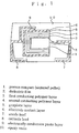
- FIG. 1 is a sectional view of a solid electrolytic capacitor in accordance with one embodiment of the present invention.
- the surface of a porous compact 1 of an electrochemical valve metal i.e., tantalum or aluminum
- an electrochemical valve metal i.e., tantalum or aluminum
- a dielectric film 2 of a metallic oxide is formed on the wall surfaces of these pores.
- first and second conducting polymer layers 3 and 4 which serve as solid electrolytes, are successively formed on the surface of the dielectric film 2 so that they penetrate deep into the pores.
- the reaction rates of conducting polymers vary according to the type and position of the substituent group(s) and the oxidation-reduction process employed. However, they qualitatively decrease in the following order: polypyrrole > polythiophene > polyaniline.
- the first conducting polymer layer 3 is formed from a compound having a lower reaction rate than the compound used to form the second conducting polymer layer 4.
- the electric conductivities of conducting polymers are affected by the type of the dopant, the degree of polymerization, and the type of the substituent group(s). However, they qualitatively decrease in the following order: polypyrrole > polythiophene > polyaniline.
- An electrode contact layer 6 serving as a cathode is formed on the surface of the second conducting polymer layer 4. In order to establish good electrical contact, a graphite layer 5 may be formed between the electrode contact layer 6 and the second conducting polymer layer 4.
- an anode lead 7 is attached to a metal rod implanted in the compact 1, and a cathode lead 8 is attached to the electrode contact layer 6 through the medium of an electrically-conductive paste layer 9.
- the present invention is further illustrated by the following examples. However, it is to be understood that the present invention is not limited to these examples.
- a porous compact comprising a sintered pellet 1 of finely powdered tantalum in the shape of a rectangular parallelepiped having 1 mm long sides was anodically oxidized at 33 V in a 0.1 wt.% aqueous solution of nitric acid. Thus, a dielectric film 2 was formed on the surfaces thereof.
- a solution was prepared by dissolving thiophene monomer and ferric p-toluenesulfonate in methanol so that thiophene monomer and ferric p-toluenesulfonate were present in a ratio of 1:2 and at a concentration of 15% by weight based on the weight of the methanol. While this solution was maintained at -30°C, the sintered pellet 1 having the dielectric film 2 formed thereon was soaked in the solution for 1 minute. Thereafter, the sintered pellet 1 was taken out and held at room temperature for 30 minutes to effect polymerization This procedure was repeated three times. Subsequently, the sintered pellet 1 was washed in butanol for 30 minutes. Thus, a first conducting polymer layer 3 comprising black polythiophene was formed on the dielectric film 2.
- a pyrrole solution was prepared by dissolving pyrrole and ferric p-toluenesulfonate in methanol so that pyrrole and ferric p-toluenesulfonate were present in a ratio of 1:2 and at a concentration of 15% by weight based on the weight of the methanol. While this pyrrole solution was maintained at -30°C, the sintered pellet 1 was soaked therein for 1 minute. Thereafter, the sintered pellet 1 was taken out and held at room temperature for 30 minutes to effect polymerization. This procedure was repeated four times. Thus, a second conducting polymer layer 4 comprising black polypyrrole was formed on the first conducting polymer layer 3.
- a capacitor was completed in the same manner as in Example 1, except that the polypyrrole constituting the second conducting polymer layer 4 in Example 1 was replaced by polyaniline.
- an aniline solution was prepared by dissolving equimolar amounts of aniline and p-toluenesulfonic acid in a mixed solvent composed of 70% by weight of methanol and 30% by weight of water so that aniline and p-toluenesulfonic acid were present at a concentration of 15% by weight based on the weight of the solvent. While this aniline solution was maintained at 0°C, the sintered pellet 1 was soaked therein for 30 seconds, and then soaked in a 25 wt.% aqueous solution of ammonium peroxodisulfate at 0°C for 30 minutes. Thereafter, the sintered pellet 1 was taken out and held at room temperature for 30 minutes to effect polymerization. This procedure was repeated five times. Thus, a second conducting polymer layer 4 comprising black polyaniline was formed.
- a capacitor was completed in the same manner as in Example 1, except that the method employed in Example 1 for the formation of the first conducting polymer layer 3 (polythiophene) was changed.
- the sintered pellet 1 was soaked in thiophene monomer for 1 minute and then held at room temperature for 5 minutes. Thereafter, the sintered pellet 1 was soaked in a 50 wt.% solution of ferric p-toluenesulfonate in butanol for 10 minutes and held at room temperature for 30 minutes to effect polymerization. This procedure was repeated three times. Subsequently, the sintered pellet 1 was washed in butanol for 30 minutes. Thus, a first conducting polymer layer 3 comprising black polythiophene was formed. Thereafter, a second conducting polymer layer comprising polypyrrole was formed in the same manner as in Example 1.
- a capacitor was completed in the same manner as in Example 1, except that the polythiophene constituting the first conducting polymer layer 3 in Example 1 was replaced by poly(3,4-ethylenedioxythiophene).
- a solution was prepared by dissolving 3,4-ethylenedioxythiophene and ferric p-toluenesulfonate in butanol so that 3,4-ethylenedioxythiophene and ferric p-toluenesulfonate were present in a ratio of 1:2 and at a concentration of 15% by weight based on the weight of the butanol. While this solution was maintained at -30°C, the sintered pellet 1 was soaked therein for 1 minute. Thereafter, the sintered pellet 1 was taken out and held at room temperature for 30 minutes to effect polymerization. This procedure was repeated three times. Subsequently, the sintered pellet 1 was washed in butanol for 15 minutes. Thus, a first conducting polymer layer 3 comprising black poly(3,4-ethylenedioxythiophene) was formed. Thereafter, a second conducting polymer layer comprising polypyrrole was formed in the same manner as in Example 1.
- a capacitor was completed in the same manner as in Example 2, except that the first conducting polymer layer 3 and the method for its formation were changed.
- a solution was prepared by dissolving 3,4-ethylenedioxythiophene and ferric p-toluenesulfonate in butanol so that 3,4-ethylenedioxythiophene and ferric p-toluenesulfonate were present in a ratio of 1:2 and at a concentration of 15% by weight based on the weight of the butanol. While this solution was maintained at -30°C, the sintered pellet 1 was soaked therein for 1 minute. Thereafter, the sintered pellet 1 was taken out and held at room temperature for 30 minutes to effect polymerization. This procedure was repeated three times. Subsequently, the sintered pellet 1 was washed in butanol for 15 minutes. Thus, a first conducting polymer layer 3 comprising black poly(3,4-ethylenedioxythiophene) was formed. Thereafter, a second conducting polymer layer comprising polyaniline was formed in the same manner as in Example 2.
- a capacitor was completed in the same manner as in Example 4, except that the method for the formation of the second conducting polymer layer 4 (polypyrrole) was changed.
- the sintered pellet 1 was soaked in pyrrole monomer for 1 minute and then held at room temperature for 5 minutes. Thereafter, the sintered pellet 1 was soaked in a 50 wt.% solution of ferric dodecylbenzenesulfonate in methanol for 10 minutes and held at room temperature for 15 minutes to effect polymerization. This procedure was repeated four times. Subsequently, the sintered pellet 1 was washed in methanol for 30 minutes. Thus, a second conducting polymer layer 4 comprising black polypyrrole was formed.
- a capacitor was completed in the same manner as in Example 1, except that, in forming the second conducting polymer layer 4 (polypyrrole), ferric dodecylbenzenesulfonate was used in place of ferric p-toluenesulfonate.
- the second conducting polymer layer 4 polypyrrole
- ferric dodecylbenzenesulfonate was used in place of ferric p-toluenesulfonate.
- a capacitor was completed in the same manner as in Example 1, except that, in forming the second conducting polymer layer 4 (polypyrrole), ferric naphthalenesulfonate was used in place of ferric p-toluenesulfonate.
- the second conducting polymer layer 4 polypyrrole
- ferric naphthalenesulfonate was used in place of ferric p-toluenesulfonate.
- a capacitor was completed in the same manner as in Example 1, except that, in forming the second conducting polymer layer 4, 3,4-dimethylpyrrole was used in place of pyrrole.
- a sintered pellet 1 of finely powdered tantalum similar to that used in Example 1 was anodically oxidized at 33 V in a 0.1 wt.% aqueous solution of nitric acid to form a dielectric film 2.
- an aniline solution was prepared by dissolving equimolar amounts of aniline and p-toluenesulfonic acid in a mixed solvent composed of 70% by weight of ethanol and 30% by weight of water so that aniline and p-toluenesulfonic acid were present at a concentration of 10% by weight based on the weight of the solvent. While this aniline solution was maintained at 0°C, the sintered pellet 1 was soaked therein for 30 seconds, and then soaked in a 25 wt.% aqueous solution of ammonium peroxodisulfate at 0°C for 30 minutes. Thereafter, the sintered pellet 1 was taken out and held at room temperature for 30 minutes to effect polymerization. This procedure was repeated twice. Thus, a first conducting polymer layer 3 comprising black polyaniline was formed on the dielectric film 2.
- a pyrrole solution was prepared by dissolving pyrrole and ferric dodecylbenzenesulfonate in methanol so that pyrrole and ferric dodecylbenzenesulfonate were present in a ratio of 1:2 and at a concentration of 15% by weight based on the weight of the methanol. While this pyrrole solution was maintained at -30°C, the sintered pellet 1 was soaked therein for 1 minute. Thereafter, the sintered pellet 1 was taken out and held at room temperature for 30 minutes to effect polymerization. This procedure was repeated four times. Thus, a second conducting polymer layer 4 comprising black polypyrrole was formed.
- a sintered pellet 1 of finely powdered tantalum similar to that used in Example 1 was anodically oxidized at 33 V in a 0.1 wt.% aqueous solution of nitric acid to form a dielectric film 2.
- a pyrrole solution was prepared by dissolving pyrrole and ferric dodecylbenzenesulfonate in methanol so that pyrrole and ferric dodecylbenzenesulfonate were present in a ratio of 1:2 and at a concentration of 15% by weight based on the weight of the methanol. While this pyrrole solution was maintained at -30°C, the sintered pellet 1 was soaked therein for 1 minute. Thereafter, the sintered pellet 1 was taken out and held at room temperature for 30 minutes to effect polymerization. This procedure was repeated three times. Thus, a first conducting polymer layer 3 comprising black polypyrrole was formed on the dielectric film 2.
- an aniline solution was prepared by dissolving equimolar amounts of aniline and p-toluenesulfonic acid in a mixed solvent composed of 70% by weight of methanol and 30% by weight of water so that aniline and p-toluenesulfonic acid were present at a concentration of 15% by weight based on the weight of the solvent. While this aniline solution was maintained at 0°C, the sintered pellet 1 was soaked therein for 30 seconds, and then soaked in a 25 wt.% aqueous solution of ammonium peroxodisulfate at 0°C for 30 minutes. Thereafter, the sintered pellet 1 was taken out and held at room temperature for 30 minutes to effect polymerization. This procedure was repeated five times. Thus, a second conducting polymer layer 4 comprising black polyaniline was formed. Thereafter, leads were attached in the same manner as in Example 1 to complete a capacitor.
- a sintered pellet 1 of finely powdered tantalum similar to that used in Example 1 was anodically oxidized at 33 V in a 0.1 wt.% aqueous solution of nitric acid to form a dielectric film 2.
- a solution was prepared by dissolving 3,4-ethylenedioxythiophene and ferric p-toluenesulfonate in butanol so that 3,4-ethylenedioxythiophene and ferric p-toluenesulfonate were present in a ratio of 1:2 and at a concentration of 15% by weight based on the weight of the butanol. While this solution was maintained at -30°C, the sintered pellet 1 was soaked therein for 1 minute. Thereafter, the sintered pellet 1 was taken out and held at room temperature for 30 minutes to effect polymerization. This procedure was repeated six times. Subsequently, the sintered pellet 1 was washed in butanol for 15 minutes. Thus, a conducting polymer layer comprising black poly(3,4-ethylenedioxythiophene) was formed.
- the capacitors obtained in the examples of the present invention show a high capacitance appearance factor even in capacitor devices having a highly extended surface area, and a low impedance which is excellent in frequency characteristics. Moreover, it can also be seen that they have excellent frequency characteristics and high heat resistance.
- the combinations of the first conducting polymer layer and the second conducting polymer layer were as follows: polythiophene/polypyrrole, polythiophene/polyaniline, poly(3,4-ethylenedioxythiophene)/polypyrrole, poly(3,4-ethylenedioxythiophene)/polyaniline and poly(3,4-ethylenedioxythiophene)/poly(3,4-dimethylpyrrole).
- polythiophene/polypyrrole polythiophene/polyaniline
- poly(3,4-ethylenedioxythiophene)/polypyrrole poly(3,4-ethylenedioxythiophene)/polyaniline
- poly(3,4-ethylenedioxythiophene)/poly(3,4-dimethylpyrrole) poly(3,4-dimethylpyrrole).
- dodecylbenzenesulfonic acid p-toluenesulfonic acid, benezenedisulfonic acid and naphthalenesulfonic acid were used as dopants.
- dodecylbenzenesulfonic acid p-toluenesulfonic acid
- benezenedisulfonic acid naphthalenesulfonic acid
- naphthalenesulfonic acid naphthalenesulfonic acid
- aromatic sulfonic acids such as sulfobenzoic acid may also be used.
Landscapes
- Engineering & Computer Science (AREA)
- Power Engineering (AREA)
- Chemical & Material Sciences (AREA)
- Chemical Kinetics & Catalysis (AREA)
- Electrochemistry (AREA)
- Microelectronics & Electronic Packaging (AREA)
- Materials Engineering (AREA)
- Polyoxymethylene Polymers And Polymers With Carbon-To-Carbon Bonds (AREA)
- Macromolecular Compounds Obtained By Forming Nitrogen-Containing Linkages In General (AREA)
Abstract
Description
- This invention relates to solid electrolytic capacitors using conducting polymer layers as solid electrolytes, and a method of making the same.
- With the progress of science and technology, a reduction in the size of electronic equipment and an improvement in the reliability thereof are being desired. In the field of capacitors, there is a growing demand for high-capacitance solid electrolytic capacitors having good characteristics even in a high frequency region and, moreover, a high degree of reliability. In order to meet this demand, research and development are being actively carried on.
- Usually, a solid electrolytic capacitor has a structure in which a porous compact of an electrochemical valve metal such as tantalum or aluminum is used as a first electrode (anode), an oxide film thereof as a dielectric, and a solid electrolyte such as manganese dioxide (MnO2) or a 7,7',8,8'-tetracyanoquinodimethane (TCNQ) complex as part of a second electrode (cathode). In this case, the solid electrolyte must perform the function of electrically connecting the whole dielectric surfaces within the porous compact with an electrode lead, and the function of repairing electrical short circuits arising from defects of the dielectric film. Consequently, metals having a high electric conductivity but lacking the dielectric repairing function cannot be used as solid electrolytes. For this reason, manganese dioxide which is converted into an insulator, for example, upon exposure to heat generated by a short-circuit current has been used. However, in capacitors using manganese dioxide as part of the cathode, the impedance in a high frequency region is not lowered because of the insufficient electric conductivity of manganese dioxide. On the other hand, capacitors using a TCNQ complex as part of the cathode have poor heat resistance because TCNQ complex are liable to thermal decomposition.
- Recently, the development of new materials in the field of polymers has made considerable progress. As a result, conducting polymers comprising conjugated polymers (e.g., polyacetylene, poly-p-phenylene, polypyrrole and polyaniline) doped with an electron-donating or electron-attracting compound (dopant) have been developed. Among others, five-membered heterocyclic compounds (e.g., polypyrrole and polythiophene) and polyaniline can easily yield conducting polymers by electrolytic polymerization, and such conducting polymers are being used as solid electrolytes for capacitors (Japanese Patent Laid-Open Nos. 36012/'89 and 64013/'91). However, this method involves electrolytic polymerization on an oxide film having electrical insulating properties, so that it has been very difficult to form a uniform conducting polymer film.
- Accordingly, a method which comprises first forming an electrically-conductive precoat layer and then forming a conducting polymer on the oxide film by electrolytic polymerization is being extensively employed (Japanese Patent Laid-Open Nos. 32619/'89, 36012/'89, 74712/'89, 225110/'89, 117121/'90, 64013/'91, 304055/'93 and 45200/'94). However, this method has the disadvantage that an auxiliary electrode must be disposed in proximity to the capacitor device, resulting in very low mass productivity.
- There has also been proposed a method for applying a conducting polymer soluble in an organic solvent and then drying it to form a polymer layer useful as a solid electrolyte. For example, it has been proposed to make a solid electrolytic capacitor using polyaniline as the solid electrolyte according to a method in which a solution of previously prepared polyaniline is applied onto the surface of an oxide film of a metal and then dried to form a layer of polyaniline (Japanese Patent Laid-Open No. 35516/'91). However, this method has the disadvantage that the polyaniline solution has very high viscosity and fails to permeate throughout an oxide film having a finely porous structure and hence a highly extended surface area. As a result, in the capacitors made by this method, the capacitance appearance factor (i.e., the ratio of the actual value of electrostatic capacity to the design value) is significantly low.
- On the other hand, a method for forming polyaniline by polymerizing aniline monomer on an oxide film is known. In this case, a satisfactorily high capacitance appearance factor can be achieved. However, since polyaniline itself has a lower electric conductivity than polypyrrole, the capacitors made by this method have the disadvantage that their characteristics in a high frequency region are poorer than those of capacitors using polypyrrole.
- Moreover, a method for forming polypyrrole by polymerizing pyrrole monomer on an oxide film is also known. However, since polypyrrole is not be easily formed in the central part of a porous body, it is difficult to coat an oxide film having a finely porous structure completely with polypyrrole. As a result, the capacitor thus obtained has the disadvantage of showing a low capacitance appearance factor.
- Furthermore, a method for forming a derivative of polythiophene on an oxide film has been proposed (Japanese Patent Laid-Open No. 15611/'90). The polymer formed by this method undergoes a high degree of shrinkage and hence tends to peel from the capacitor device, resulting an increase in impedance. Moreover, since the oxide film is exposed in the parts where the polymer has peeled off, the device becomes mechanically weak against external stresses and tends to show an increase in leakage current. Thus, it is impossible to secure the reliability of the device.
- Furthermore, it has been proposed to use two layers of conducting polymer having different properties as solid electrolytes and thereby make the most of the characteristics of each compound (Japanese Patent Laid-Open Nos. 45481/'95, 45199/'94 and 45201/'94). Specifically, according to this method, the capacitance appearance factor of a capacitor can be enhanced by forming relatively easily formable polyaniline in the inside of the device and then forming polypyrrole thereon, or the heat resistance of a capacitor can be improved by forming polypyrrole having a high electric conductivity in the inside of the device and then forming thereon polyaniline having high heat resistance. In the former case (polyaniline/ polypyrrole), the capacitance appearance factor is enhanced, but the impedance in a high frequency region is not sufficiently lowered because of the low electric conductivity of polyacetylene. In the latter case (polypyrrole/polyaniline), the heat resistance is improved, but the capacitance appearance factor is reduced because polypyrrole cannot be easily formed in the inside of the device.
- As described above, conventional solid electrolytic capacitors have involved difficulty in improving their capacitance appearance factor, frequency characteristics, heat resistance and reliability at the same time.
- An object of the present invention is to provide a solid electrolytic capacitor having high heat resistance and showing an improvement in capacitance appearance factor and frequency characteristics, as well as a method of making the same.
- A first aspect of the present invention relates to a solid electrolytic capacitor using conducting polymers. Specifically, according to this first aspect, there is provided a solid electrolytic capacitor using an oxide film of an electrochemical valve metal as the dielectric and having, as solid electrolytes, first and second conducting polymer layers formed successively on the oxide film by polymerization reactions, wherein the first conducting polymer layer is formed from a compound having a lower reaction rate than the compound used to form the second conducting polymer layer.
- A second aspect of the present invention relates to a method of making a solid electrolytic capacitor using conducting polymers. Specifically, according to this second aspect, there is provided a method of making a solid electrolytic capacitor using an oxide film of an electrochemical valve metal as the dielectric and having, as solid electrolytes, first and second conducting polymer layers formed successively on the oxide film, which comprises forming the first and second conducting polymer layers by chemical oxidative polymerization processes using an oxidizing agent, and forming the first conducting polymer layer from a compound having a lower reaction rate than the compound used to form the second conducting polymer layer.
- A first effect of the present invention is that a high capacitance appearance factor can be achieved in capacitor devices having a finely porous structure and hence a highly extended surface area.
- A second effect of the present invention is that solid electrolytic capacitors having good frequency characteristics can be made.
- A third effect of the present invention is that highly reliable solid electrolytic capacitors having excellent heat resistance and a method of making the same can be provided.
-
- FIG. 1 is a sectional view of a solid electrolytic
capacitor made in accordance with one embodiment of the
present invention. In this figure,
numeral 1 designates a porous compact (or sintered pellet); 2, a dielectric film; 3, a first conducting polymer layer; 4, a second conducting polymer layer; 5, a graphite layer; 6, an electrode contact layer; 7, an anode lead; 8, a cathode lead; 9, an electrically-conductive paste layer; and 10, an epoxy resin. -
- In one embodiment of the present invention, the polymerization reactions are carried out by chemical oxidative polymerization processes using an oxidizing agent, and the first and second conducting polymer layers formed on the oxide film each comprise a layer of a polymer of aniline, pyrrole, thiophene or a derivative thereof.
- In preferred embodiments of the present invention, for example, a polymer of thiophene or a derivative thereof which is obtained by the chemical oxidative polymerization of thiophene monomer or a derivative thereof is used as the first conducting polymer having a lower reaction rate. Then, a polymer of pyrrole or a derivative thereof is formed on its outer surface as a conducting polymer having a higher electric conductivity, or a polymer of aniline or a derivative thereof is formed on its outer surface as a conducting polymer having higher heat resistance.
- More specifically, several preferred embodiments as follows:
- the first conducting polymer layer comprising a polymer of thiophene or a derivative thereof and the second conducting polymer layer comprising a polymer of aniline or a derivative thereof are each formed by a chemical oxidative polymerization process using an oxidizing agent;
- the first conducting polymer layer comprising a polymer of thiophene or a derivative thereof and the second conducting polymer layer comprising a polymer of pyrrole or a derivative thereof are each formed by a chemical oxidative polymerization process using an oxidizing agent;
- the first conducting polymer layer comprising a polymer of 3,4-ethylenedioxythiophene and the second conducting polymer layer comprising a polymer of aniline or a derivative thereof are each formed by a chemical oxidative polymerization process using an oxidizing agent; or
- the first conducting polymer layer comprising a polymer of 3,4-ethylenedioxythiophene and the second conducting polymer layer comprising a polymer of pyrrole or a derivative thereof are each formed by a chemical oxidative polymerization process using an oxidizing agent.
-
- Now, the present invention is explained with reference to the accompanying drawing. FIG. 1 is a sectional view of a solid electrolytic capacitor in accordance with one embodiment of the present invention.
- The surface of a porous compact 1 of an electrochemical valve metal (i.e., tantalum or aluminum), which serves as an anode, has very fine pores so as to extend its surface area. A
dielectric film 2 of a metallic oxide is formed on the wall surfaces of these pores. Then, first and second conductingpolymer layers 3 and 4, which serve as solid electrolytes, are successively formed on the surface of thedielectric film 2 so that they penetrate deep into the pores. The reaction rates of conducting polymers vary according to the type and position of the substituent group(s) and the oxidation-reduction process employed. However, they qualitatively decrease in the following order: polypyrrole > polythiophene > polyaniline. The firstconducting polymer layer 3 is formed from a compound having a lower reaction rate than the compound used to form the second conducting polymer layer 4. - The electric conductivities of conducting polymers are affected by the type of the dopant, the degree of polymerization, and the type of the substituent group(s). However, they qualitatively decrease in the following order: polypyrrole > polythiophene > polyaniline. An
electrode contact layer 6 serving as a cathode is formed on the surface of the second conducting polymer layer 4. In order to establish good electrical contact, a graphite layer 5 may be formed between theelectrode contact layer 6 and the second conducting polymer layer 4. Moreover, ananode lead 7 is attached to a metal rod implanted in the compact 1, and acathode lead 8 is attached to theelectrode contact layer 6 through the medium of an electrically-conductive paste layer 9. - Referring to FIG. 1, the present invention is further illustrated by the following examples. However, it is to be understood that the present invention is not limited to these examples.
- A porous compact comprising a
sintered pellet 1 of finely powdered tantalum in the shape of a rectangular parallelepiped having 1 mm long sides was anodically oxidized at 33 V in a 0.1 wt.% aqueous solution of nitric acid. Thus, adielectric film 2 was formed on the surfaces thereof. - Then, a solution was prepared by dissolving thiophene monomer and ferric p-toluenesulfonate in methanol so that thiophene monomer and ferric p-toluenesulfonate were present in a ratio of 1:2 and at a concentration of 15% by weight based on the weight of the methanol. While this solution was maintained at -30°C, the
sintered pellet 1 having thedielectric film 2 formed thereon was soaked in the solution for 1 minute. Thereafter, thesintered pellet 1 was taken out and held at room temperature for 30 minutes to effect polymerization This procedure was repeated three times. Subsequently, thesintered pellet 1 was washed in butanol for 30 minutes. Thus, a firstconducting polymer layer 3 comprising black polythiophene was formed on thedielectric film 2. - Then, a pyrrole solution was prepared by dissolving pyrrole and ferric p-toluenesulfonate in methanol so that pyrrole and ferric p-toluenesulfonate were present in a ratio of 1:2 and at a concentration of 15% by weight based on the weight of the methanol. While this pyrrole solution was maintained at -30°C, the
sintered pellet 1 was soaked therein for 1 minute. Thereafter, thesintered pellet 1 was taken out and held at room temperature for 30 minutes to effect polymerization. This procedure was repeated four times. Thus, a second conducting polymer layer 4 comprising black polypyrrole was formed on the firstconducting polymer layer 3. Moreover, a carbon paste and a silver paste were successively applied and dried to form a graphite layer 5 and anelectrode contact layer 6, respectively. Finally, ananode lead 7 and acathode lead 8 were attached and the whole assembly was encapsulated with anepoxy resin 10 to complete a capacitor. - A capacitor was completed in the same manner as in Example 1, except that the polypyrrole constituting the second conducting polymer layer 4 in Example 1 was replaced by polyaniline.
- Specifically, after the formation of the first
conducting polymer layer 3, an aniline solution was prepared by dissolving equimolar amounts of aniline and p-toluenesulfonic acid in a mixed solvent composed of 70% by weight of methanol and 30% by weight of water so that aniline and p-toluenesulfonic acid were present at a concentration of 15% by weight based on the weight of the solvent. While this aniline solution was maintained at 0°C, thesintered pellet 1 was soaked therein for 30 seconds, and then soaked in a 25 wt.% aqueous solution of ammonium peroxodisulfate at 0°C for 30 minutes. Thereafter, thesintered pellet 1 was taken out and held at room temperature for 30 minutes to effect polymerization. This procedure was repeated five times. Thus, a second conducting polymer layer 4 comprising black polyaniline was formed. - A capacitor was completed in the same manner as in Example 1, except that the method employed in Example 1 for the formation of the first conducting polymer layer 3 (polythiophene) was changed.
- Specifically, the
sintered pellet 1 was soaked in thiophene monomer for 1 minute and then held at room temperature for 5 minutes. Thereafter, thesintered pellet 1 was soaked in a 50 wt.% solution of ferric p-toluenesulfonate in butanol for 10 minutes and held at room temperature for 30 minutes to effect polymerization. This procedure was repeated three times. Subsequently, thesintered pellet 1 was washed in butanol for 30 minutes. Thus, a firstconducting polymer layer 3 comprising black polythiophene was formed. Thereafter, a second conducting polymer layer comprising polypyrrole was formed in the same manner as in Example 1. - A capacitor was completed in the same manner as in Example 1, except that the polythiophene constituting the first
conducting polymer layer 3 in Example 1 was replaced by poly(3,4-ethylenedioxythiophene). - Specifically, a solution was prepared by dissolving 3,4-ethylenedioxythiophene and ferric p-toluenesulfonate in butanol so that 3,4-ethylenedioxythiophene and ferric p-toluenesulfonate were present in a ratio of 1:2 and at a concentration of 15% by weight based on the weight of the butanol. While this solution was maintained at -30°C, the
sintered pellet 1 was soaked therein for 1 minute. Thereafter, thesintered pellet 1 was taken out and held at room temperature for 30 minutes to effect polymerization. This procedure was repeated three times. Subsequently, thesintered pellet 1 was washed in butanol for 15 minutes. Thus, a firstconducting polymer layer 3 comprising black poly(3,4-ethylenedioxythiophene) was formed. Thereafter, a second conducting polymer layer comprising polypyrrole was formed in the same manner as in Example 1. - A capacitor was completed in the same manner as in Example 2, except that the first
conducting polymer layer 3 and the method for its formation were changed. - Specifically, a solution was prepared by dissolving 3,4-ethylenedioxythiophene and ferric p-toluenesulfonate in butanol so that 3,4-ethylenedioxythiophene and ferric p-toluenesulfonate were present in a ratio of 1:2 and at a concentration of 15% by weight based on the weight of the butanol. While this solution was maintained at -30°C, the
sintered pellet 1 was soaked therein for 1 minute. Thereafter, thesintered pellet 1 was taken out and held at room temperature for 30 minutes to effect polymerization. This procedure was repeated three times. Subsequently, thesintered pellet 1 was washed in butanol for 15 minutes. Thus, a firstconducting polymer layer 3 comprising black poly(3,4-ethylenedioxythiophene) was formed. Thereafter, a second conducting polymer layer comprising polyaniline was formed in the same manner as in Example 2. - A capacitor was completed in the same manner as in Example 4, except that the method for the formation of the second conducting polymer layer 4 (polypyrrole) was changed.
- Specifically, after the formation of the first
conducting polymer layer 3 comprising poly(3,4-ethylenedioxythiophene), thesintered pellet 1 was soaked in pyrrole monomer for 1 minute and then held at room temperature for 5 minutes. Thereafter, thesintered pellet 1 was soaked in a 50 wt.% solution of ferric dodecylbenzenesulfonate in methanol for 10 minutes and held at room temperature for 15 minutes to effect polymerization. This procedure was repeated four times. Subsequently, thesintered pellet 1 was washed in methanol for 30 minutes. Thus, a second conducting polymer layer 4 comprising black polypyrrole was formed. - A capacitor was completed in the same manner as in Example 1, except that, in forming the second conducting polymer layer 4 (polypyrrole), ferric dodecylbenzenesulfonate was used in place of ferric p-toluenesulfonate.
- A capacitor was completed in the same manner as in Example 1, except that, in forming the second conducting polymer layer 4 (polypyrrole), ferric naphthalenesulfonate was used in place of ferric p-toluenesulfonate.
- A capacitor was completed in the same manner as in Example 1, except that, in forming the second
conducting polymer layer 4, 3,4-dimethylpyrrole was used in place of pyrrole. - A
sintered pellet 1 of finely powdered tantalum similar to that used in Example 1 was anodically oxidized at 33 V in a 0.1 wt.% aqueous solution of nitric acid to form adielectric film 2. - Then, an aniline solution was prepared by dissolving equimolar amounts of aniline and p-toluenesulfonic acid in a mixed solvent composed of 70% by weight of ethanol and 30% by weight of water so that aniline and p-toluenesulfonic acid were present at a concentration of 10% by weight based on the weight of the solvent. While this aniline solution was maintained at 0°C, the
sintered pellet 1 was soaked therein for 30 seconds, and then soaked in a 25 wt.% aqueous solution of ammonium peroxodisulfate at 0°C for 30 minutes. Thereafter, thesintered pellet 1 was taken out and held at room temperature for 30 minutes to effect polymerization. This procedure was repeated twice. Thus, a firstconducting polymer layer 3 comprising black polyaniline was formed on thedielectric film 2. - Then, a pyrrole solution was prepared by dissolving pyrrole and ferric dodecylbenzenesulfonate in methanol so that pyrrole and ferric dodecylbenzenesulfonate were present in a ratio of 1:2 and at a concentration of 15% by weight based on the weight of the methanol. While this pyrrole solution was maintained at -30°C, the
sintered pellet 1 was soaked therein for 1 minute. Thereafter, thesintered pellet 1 was taken out and held at room temperature for 30 minutes to effect polymerization. This procedure was repeated four times. Thus, a second conducting polymer layer 4 comprising black polypyrrole was formed. Moreover, a carbon paste and a silver paste were successively applied and dried to form a graphite layer 5 and anelectrode contact layer 6, respectively. Finally, ananode lead 7 and acathode lead 8 were attached and the whole assembly was encapsulated with anepoxy resin 10 to complete a capacitor. - A
sintered pellet 1 of finely powdered tantalum similar to that used in Example 1 was anodically oxidized at 33 V in a 0.1 wt.% aqueous solution of nitric acid to form adielectric film 2. - Then, a pyrrole solution was prepared by dissolving pyrrole and ferric dodecylbenzenesulfonate in methanol so that pyrrole and ferric dodecylbenzenesulfonate were present in a ratio of 1:2 and at a concentration of 15% by weight based on the weight of the methanol. While this pyrrole solution was maintained at -30°C, the
sintered pellet 1 was soaked therein for 1 minute. Thereafter, thesintered pellet 1 was taken out and held at room temperature for 30 minutes to effect polymerization. This procedure was repeated three times. Thus, a firstconducting polymer layer 3 comprising black polypyrrole was formed on thedielectric film 2. - Then, an aniline solution was prepared by dissolving equimolar amounts of aniline and p-toluenesulfonic acid in a mixed solvent composed of 70% by weight of methanol and 30% by weight of water so that aniline and p-toluenesulfonic acid were present at a concentration of 15% by weight based on the weight of the solvent. While this aniline solution was maintained at 0°C, the
sintered pellet 1 was soaked therein for 30 seconds, and then soaked in a 25 wt.% aqueous solution of ammonium peroxodisulfate at 0°C for 30 minutes. Thereafter, thesintered pellet 1 was taken out and held at room temperature for 30 minutes to effect polymerization. This procedure was repeated five times. Thus, a second conducting polymer layer 4 comprising black polyaniline was formed. Thereafter, leads were attached in the same manner as in Example 1 to complete a capacitor. - A
sintered pellet 1 of finely powdered tantalum similar to that used in Example 1 was anodically oxidized at 33 V in a 0.1 wt.% aqueous solution of nitric acid to form adielectric film 2. - Then, a solution was prepared by dissolving 3,4-ethylenedioxythiophene and ferric p-toluenesulfonate in butanol so that 3,4-ethylenedioxythiophene and ferric p-toluenesulfonate were present in a ratio of 1:2 and at a concentration of 15% by weight based on the weight of the butanol. While this solution was maintained at -30°C, the
sintered pellet 1 was soaked therein for 1 minute. Thereafter, thesintered pellet 1 was taken out and held at room temperature for 30 minutes to effect polymerization. This procedure was repeated six times. Subsequently, thesintered pellet 1 was washed in butanol for 15 minutes. Thus, a conducting polymer layer comprising black poly(3,4-ethylenedioxythiophene) was formed. - With respect to each of the solid electrolytic capacitors obtained in the foregoing examples and comparative examples, the types of the conducting polymer layers used, the capacitance appearance factor C/Co (in which Co is the capacitance in an electrolytic solution), and the leakage currents (LC) and resonance frequency impedances (Z) before and after a high-temperature exposure test (at 150°C for 500 hours) are shown in Table 1.

- As can be seen from Table 1, the capacitors obtained in the examples of the present invention show a high capacitance appearance factor even in capacitor devices having a highly extended surface area, and a low impedance which is excellent in frequency characteristics. Moreover, it can also be seen that they have excellent frequency characteristics and high heat resistance.
- In the foregoing examples, the combinations of the first conducting polymer layer and the second conducting polymer layer were as follows: polythiophene/polypyrrole, polythiophene/polyaniline, poly(3,4-ethylenedioxythiophene)/polypyrrole, poly(3,4-ethylenedioxythiophene)/polyaniline and poly(3,4-ethylenedioxythiophene)/poly(3,4-dimethylpyrrole). However, it is to be understood that the present invention is not limited to these combinations.
- Moreover, dodecylbenzenesulfonic acid, p-toluenesulfonic acid, benezenedisulfonic acid and naphthalenesulfonic acid were used as dopants. However, it is to be understood that the present invention is not limited to these dopants. For example, aromatic sulfonic acids such as sulfobenzoic acid may also be used.
Claims (11)
- A solid electrolytic capacitor using an oxide film of an electrochemical valve metal as the dielectric and having, as solid electrolytes, first and second conducting polymer layers formed successively on the oxide film by polymerization reactions, wherein said first conducting polymer layer is formed from a compound having a lower reaction rate than the compound used to form said second conducting polymer layer.
- A solid electrolytic capacitor as claimed in claim 1 wherein the polymerization reactions are carried out by chemical oxidative polymerization processes using an oxidizing agent, and said first and second conducting polymer layers each comprise a polymer of aniline, pyrrole, thiophene or a derivative thereof.
- A solid electrolytic capacitor as claimed in claim 1 wherein said first conducting polymer layer comprises a polymer of thiophene or a derivative thereof and said second conducting polymer layer comprises a polymer of aniline or a derivative thereof.
- A solid electrolytic capacitor as claimed in claim 1 wherein said first conducting polymer layer comprises a polymer of thiophene or a derivative thereof and said second conducting polymer layer comprises a polymer of pyrrole or a derivative thereof.
- A solid electrolytic capacitor as claimed in claim 1 wherein said first conducting polymer layer comprises a polymer of 3,4-ethylenedioxythiophene and said second conducting polymer layer comprises a polymer of aniline or a derivative thereof.
- A solid electrolytic capacitor as claimed in claim 1 wherein said first conducting polymer layer comprises a polymer of 3,4-ethylenedioxythiophene and said second conducting polymer layer comprises a polymer of pyrrole or a derivative thereof.
- A method of making a solid electrolytic capacitor using an oxide film of an electrochemical valve metal as the dielectric and having, as solid electrolytes, first and second conducting polymer layers formed successively on the oxide film, which comprises forming said first and second conducting polymer layers by chemical oxidative polymerization processes using an oxidizing agent, and forming said first conducting polymer layer from a compound having a lower reaction rate than the compound used to form said second conducting polymer layer.
- A method of making a solid electrolytic capacitor as claimed in claim 7 wherein said first conducting polymer layer comprising a polymer of thiophene or a derivative thereof and said second conducting polymer layer comprising a polymer of aniline or a derivative thereof are each formed by a chemical oxidative polymerization process using an oxidizing agent.
- A method of making a solid electrolytic capacitor as claimed in claim 7 wherein said first conducting polymer layer comprising a polymer of thiophene or a derivative thereof and said second conducting polymer layer comprising a polymer of pyrrole or a derivative thereof are each formed by a chemical oxidative polymerization process using an oxidizing agent.
- A method of making a solid electrolytic capacitor as claimed in claim 7 wherein said first conducting polymer layer comprising a polymer of 3,4-ethylenedioxythiophene and said second conducting polymer layer comprising a polymer of aniline or a derivative thereof are each formed by a chemical oxidative polymerization process using an oxidizing agent.
- A method of making a solid electrolytic capacitor as claimed in claim 7 wherein said first conducting polymer layer comprising a polymer of 3,4-ethylenedioxythiophene and said second conducting polymer layer comprising a polymer of pyrrole or a derivative thereof are each formed by a chemical oxidative polymerization process using an oxidizing agent.
Applications Claiming Priority (3)
| Application Number | Priority Date | Filing Date | Title |
|---|---|---|---|
| JP20487797A JP3157748B2 (en) | 1997-07-30 | 1997-07-30 | Solid electrolytic capacitor using conductive polymer and method for manufacturing the same |
| JP20487797 | 1997-07-30 | ||
| JP204877/97 | 1997-07-30 |
Publications (3)
| Publication Number | Publication Date |
|---|---|
| EP0895259A2 true EP0895259A2 (en) | 1999-02-03 |
| EP0895259A3 EP0895259A3 (en) | 2001-04-25 |
| EP0895259B1 EP0895259B1 (en) | 2008-07-16 |
Family
ID=16497885
Family Applications (1)
| Application Number | Title | Priority Date | Filing Date |
|---|---|---|---|
| EP98114011A Expired - Lifetime EP0895259B1 (en) | 1997-07-30 | 1998-07-27 | Solid electrolytic capacitor using conducting polymers and method of making same |
Country Status (5)
| Country | Link |
|---|---|
| US (2) | US6154358A (en) |
| EP (1) | EP0895259B1 (en) |
| JP (1) | JP3157748B2 (en) |
| KR (1) | KR100334918B1 (en) |
| DE (1) | DE69839716D1 (en) |
Cited By (7)
| Publication number | Priority date | Publication date | Assignee | Title |
|---|---|---|---|---|
| EP0820076A2 (en) † | 1996-07-16 | 1998-01-21 | Nec Corporation | Solid electrolyte capacitor and method for manufacturing the same |
| EP0974988A2 (en) * | 1998-07-07 | 2000-01-26 | Matsushita Electric Industrial Co., Ltd. | Method of producing electrolytic capacitor |
| EP1073074A2 (en) * | 1999-07-30 | 2001-01-31 | Nec Corporation | Solid electrolytic capacitors and method for manufacturing the same |
| EP1100097A1 (en) * | 1998-06-25 | 2001-05-16 | Nichicon Corporation | Solid electrolytic capacitor and process for producing the same |
| WO2001052288A1 (en) * | 2000-01-07 | 2001-07-19 | Kemet Electronics Corporation | Solid electrolytic capacitor with low esr and high humidity resistance |
| EP1154449A2 (en) * | 2000-05-11 | 2001-11-14 | Nec Corporation | Manufacturing method of solid electrolytic capacitor |
| GB2474747A (en) * | 2009-10-23 | 2011-04-27 | Avx Corp | Polymer Solid Electrolytic Capacitor |
Families Citing this family (36)
| Publication number | Priority date | Publication date | Assignee | Title |
|---|---|---|---|---|
| KR100417456B1 (en) * | 1999-09-10 | 2004-02-05 | 마쯔시다덴기산교 가부시키가이샤 | Solid electrolytic capacitor and production method thereof, and conductive polymer polymerizing oxidizing agent solution |
| US6602741B1 (en) * | 1999-09-14 | 2003-08-05 | Matsushita Electric Industrial Co., Ltd. | Conductive composition precursor, conductive composition, solid electrolytic capacitor, and their manufacturing method |
| JP3465076B2 (en) * | 1999-10-12 | 2003-11-10 | Necトーキン株式会社 | Solid electrolytic capacitors |
| JP3881480B2 (en) | 1999-10-14 | 2007-02-14 | ローム株式会社 | Solid electrolytic capacitor and manufacturing method thereof |
| TW502267B (en) * | 2000-01-28 | 2002-09-11 | Matsushita Electric Ind Co Ltd | Solid eleotrolytic capacitors and method for manufacturing the same |
| US6430032B2 (en) * | 2000-07-06 | 2002-08-06 | Showa Denko K. K. | Solid electrolytic capacitor and method for producing the same |
| US6674635B1 (en) | 2001-06-11 | 2004-01-06 | Avx Corporation | Protective coating for electrolytic capacitors |
| TWI254333B (en) * | 2002-03-18 | 2006-05-01 | Sanyo Electric Co | Solid electrolytic capacitor and method of manufacturing same |
| JP4010447B2 (en) * | 2002-05-30 | 2007-11-21 | ローム株式会社 | Solid electrolytic capacitor and manufacturing method thereof |
| US6864147B1 (en) | 2002-06-11 | 2005-03-08 | Avx Corporation | Protective coating for electrolytic capacitors |
| JP2004063822A (en) * | 2002-07-30 | 2004-02-26 | Fujitsu Media Device Kk | Chip-type solid electrolytic capacitor |
| JP4366055B2 (en) * | 2002-08-01 | 2009-11-18 | ローム株式会社 | Manufacturing method of solid electrolytic capacitor |
| JP4529687B2 (en) * | 2002-09-30 | 2010-08-25 | 日本ケミコン株式会社 | Manufacturing method of solid electrolytic capacitor |
| US7079377B2 (en) * | 2002-09-30 | 2006-07-18 | Joachim Hossick Schott | Capacitor and method for producing a capacitor |
| CN1748272A (en) * | 2003-02-10 | 2006-03-15 | Tdk株式会社 | Solid electrolytic capacitor and process for its fabrication |
| US7256982B2 (en) * | 2003-05-30 | 2007-08-14 | Philip Michael Lessner | Electrolytic capacitor |
| JP2005093591A (en) * | 2003-09-16 | 2005-04-07 | Sanyo Electric Co Ltd | Solid electrolytic capacitor |
| DE102004022110A1 (en) * | 2004-05-05 | 2005-12-01 | H.C. Starck Gmbh | Process for the preparation of electrolytic capacitors |
| JP4701680B2 (en) * | 2004-11-05 | 2011-06-15 | Tdk株式会社 | Solid electrolytic capacitor and manufacturing method thereof |
| JP4799853B2 (en) * | 2004-11-22 | 2011-10-26 | 株式会社フジクラ | Electrode for photoelectric conversion element, photoelectric conversion element, and dye-sensitized solar cell |
| JP4799852B2 (en) * | 2004-11-22 | 2011-10-26 | 株式会社フジクラ | Electrode for photoelectric conversion element, photoelectric conversion element, and dye-sensitized solar cell |
| US7324329B2 (en) * | 2005-12-22 | 2008-01-29 | Giner, Inc. | Electrochemical-electrolytic capacitor and method of making the same |
| WO2007077883A1 (en) * | 2005-12-28 | 2007-07-12 | Showa Denko K. K. | Capacitor and method for manufacturing same |
| US20070171596A1 (en) * | 2006-01-20 | 2007-07-26 | Chacko Antony P | Electrode compositions containing carbon nanotubes for solid electrolyte capacitors |
| US7483259B2 (en) * | 2007-03-21 | 2009-01-27 | Avx Corporation | Solid electrolytic capacitor containing a barrier layer |
| US7515396B2 (en) * | 2007-03-21 | 2009-04-07 | Avx Corporation | Solid electrolytic capacitor containing a conductive polymer |
| US7460358B2 (en) * | 2007-03-21 | 2008-12-02 | Avx Corporation | Solid electrolytic capacitor containing a protective adhesive layer |
| JP2009209259A (en) * | 2008-03-04 | 2009-09-17 | Nec Tokin Corp | Electroconductive polymer and solid electrolytic capacitor using it |
| JP4635113B2 (en) * | 2009-03-02 | 2011-02-16 | 昭和電工株式会社 | Manufacturing method of solid electrolytic capacitor |
| JP2011124544A (en) * | 2009-09-30 | 2011-06-23 | Hc Starck Clevios Gmbh | Monomer of selected color number and capacitor prepared therefrom |
| US8946903B2 (en) | 2010-07-09 | 2015-02-03 | Micron Technology, Inc. | Electrically conductive laminate structure containing graphene region |
| US9767964B2 (en) | 2011-04-07 | 2017-09-19 | Avx Corporation | Multi-anode solid electrolytic capacitor assembly |
| WO2015040883A1 (en) * | 2013-09-20 | 2015-03-26 | 株式会社村田製作所 | Method for manufacturing solid electrolytic capacitor |
| JP7108811B2 (en) * | 2016-08-31 | 2022-07-29 | パナソニックIpマネジメント株式会社 | Electrolytic capacitor and manufacturing method thereof |
| US11270847B1 (en) | 2019-05-17 | 2022-03-08 | KYOCERA AVX Components Corporation | Solid electrolytic capacitor with improved leakage current |
| JPWO2021172031A1 (en) * | 2020-02-28 | 2021-09-02 |
Citations (1)
| Publication number | Priority date | Publication date | Assignee | Title |
|---|---|---|---|---|
| JPH0974050A (en) * | 1995-06-26 | 1997-03-18 | Matsushita Electric Ind Co Ltd | Capacitor and its manufacture |
Family Cites Families (21)
| Publication number | Priority date | Publication date | Assignee | Title |
|---|---|---|---|---|
| US158236A (en) * | 1874-12-29 | Improvement in dumping-cars | ||
| JPS6432619A (en) * | 1987-07-29 | 1989-02-02 | Japan Carlit Co Ltd | Manufacture of solid electrolytic capacitor |
| JPS6436012A (en) * | 1987-07-31 | 1989-02-07 | Asahi Glass Co Ltd | Solid electrolytic capacitor |
| JPS6474712A (en) * | 1987-09-17 | 1989-03-20 | Japan Carlit Co Ltd | Manufacture of solid electrolytic capacitor |
| JPH01225110A (en) * | 1988-03-04 | 1989-09-08 | Asahi Glass Co Ltd | Solid electrolytic capacitor |
| DE3814730A1 (en) | 1988-04-30 | 1989-11-09 | Bayer Ag | SOLID ELECTROLYTE AND ELECTROLYTE CONDENSERS CONTAINING THEM |
| JPH02117121A (en) * | 1988-10-27 | 1990-05-01 | Marcon Electron Co Ltd | Solid electrolytic capacitor |
| JP2631896B2 (en) * | 1989-06-30 | 1997-07-16 | 日東電工株式会社 | Solid electrolytic capacitor and method of manufacturing the same |
| JPH0364013A (en) * | 1989-08-02 | 1991-03-19 | Marcon Electron Co Ltd | Solid electrolytic capacitor and manufacture thereof |
| JPH04137517A (en) * | 1990-09-27 | 1992-05-12 | Marcon Electron Co Ltd | Manufacture of solid electrolytic capacitor |
| JP3522294B2 (en) * | 1992-04-25 | 2004-04-26 | ニチコン株式会社 | Method for manufacturing solid electrolytic capacitor |
| JP3542613B2 (en) * | 1992-07-24 | 2004-07-14 | 日本ケミコン株式会社 | Method for manufacturing solid electrolytic capacitor |
| JPH0645200A (en) * | 1992-07-24 | 1994-02-18 | Nippon Chemicon Corp | Solid-state electrolytic capacitor |
| JPH0645199A (en) * | 1992-07-24 | 1994-02-18 | Nippon Chemicon Corp | Solid-state electrolytic capacitor |
| JP2765462B2 (en) * | 1993-07-27 | 1998-06-18 | 日本電気株式会社 | Solid electrolytic capacitor and method of manufacturing the same |
| JPH0745481A (en) * | 1993-07-29 | 1995-02-14 | Nec Corp | Solid electrolytic capacitor and manufacture thereof |
| JP3068430B2 (en) * | 1995-04-25 | 2000-07-24 | 富山日本電気株式会社 | Solid electrolytic capacitor and method of manufacturing the same |
| JP3294973B2 (en) * | 1995-09-21 | 2002-06-24 | 旭光学工業株式会社 | Camera barrier movement restriction mechanism |
| US5812367A (en) * | 1996-04-04 | 1998-09-22 | Matsushita Electric Industrial Co., Ltd. | Solid electrolytic capacitors comprising a conductive layer made of a polymer of pyrrole or its derivative |
| WO1997041577A1 (en) * | 1996-04-26 | 1997-11-06 | Nippon Chemi-Con Corporation | Solid electrolyte capacitor and its manufacture |
| JPH10284351A (en) | 1997-04-09 | 1998-10-23 | Nichicon Corp | Solid-state electrolytic capacitor and manufacture of the same |
-
1997
- 1997-07-30 JP JP20487797A patent/JP3157748B2/en not_active Expired - Fee Related
-
1998
- 1998-07-23 US US09/121,269 patent/US6154358A/en not_active Expired - Lifetime
- 1998-07-27 EP EP98114011A patent/EP0895259B1/en not_active Expired - Lifetime
- 1998-07-27 DE DE69839716T patent/DE69839716D1/en not_active Expired - Fee Related
- 1998-07-29 KR KR1019980030562A patent/KR100334918B1/en not_active IP Right Cessation
-
2000
- 2000-07-26 US US09/626,076 patent/US6210450B1/en not_active Expired - Lifetime
Patent Citations (1)
| Publication number | Priority date | Publication date | Assignee | Title |
|---|---|---|---|---|
| JPH0974050A (en) * | 1995-06-26 | 1997-03-18 | Matsushita Electric Ind Co Ltd | Capacitor and its manufacture |
Non-Patent Citations (1)
| Title |
|---|
| PATENT ABSTRACTS OF JAPAN vol. 1997, no. 07, 31 July 1997 (1997-07-31) -& JP 09 074050 A (MATSUSHITA ELECTRIC IND CO LTD), 18 March 1997 (1997-03-18) -& EP 0 803 886 A (MATSUSHITA ELECTRIC IND CO LTD) 29 October 1997 (1997-10-29) * |
Cited By (15)
| Publication number | Priority date | Publication date | Assignee | Title |
|---|---|---|---|---|
| EP0820076B2 (en) † | 1996-07-16 | 2011-03-02 | Nec Tokin Corporation | Solid electrolyte capacitor and method for manufacturing the same |
| EP0820076A2 (en) † | 1996-07-16 | 1998-01-21 | Nec Corporation | Solid electrolyte capacitor and method for manufacturing the same |
| EP1100097A4 (en) * | 1998-06-25 | 2004-12-08 | Nichicon Corp | Solid electrolytic capacitor and process for producing the same |
| EP1100097A1 (en) * | 1998-06-25 | 2001-05-16 | Nichicon Corporation | Solid electrolytic capacitor and process for producing the same |
| EP0974988A2 (en) * | 1998-07-07 | 2000-01-26 | Matsushita Electric Industrial Co., Ltd. | Method of producing electrolytic capacitor |
| EP0974988A3 (en) * | 1998-07-07 | 2001-04-25 | Matsushita Electric Industrial Co., Ltd. | Method of producing electrolytic capacitor |
| EP1073074A2 (en) * | 1999-07-30 | 2001-01-31 | Nec Corporation | Solid electrolytic capacitors and method for manufacturing the same |
| EP1073074A3 (en) * | 1999-07-30 | 2006-06-14 | Nec Tokin Corporation | Solid electrolytic capacitors and method for manufacturing the same |
| US6304427B1 (en) | 2000-01-07 | 2001-10-16 | Kemet Electronics Corporation | Combinations of materials to minimize ESR and maximize ESR stability of surface mount valve-metal capacitors after exposure to heat and/or humidity |
| WO2001052288A1 (en) * | 2000-01-07 | 2001-07-19 | Kemet Electronics Corporation | Solid electrolytic capacitor with low esr and high humidity resistance |
| EP1154449A3 (en) * | 2000-05-11 | 2006-05-10 | NEC TOKIN Toyama, Ltd. | Manufacturing method of solid electrolytic capacitor |
| EP1154449A2 (en) * | 2000-05-11 | 2001-11-14 | Nec Corporation | Manufacturing method of solid electrolytic capacitor |
| GB2474747A (en) * | 2009-10-23 | 2011-04-27 | Avx Corp | Polymer Solid Electrolytic Capacitor |
| US8125768B2 (en) | 2009-10-23 | 2012-02-28 | Avx Corporation | External coating for a solid electrolytic capacitor |
| GB2474747B (en) * | 2009-10-23 | 2013-11-20 | Avx Corp | External coating for a solid electrolytic capacitor |
Also Published As
| Publication number | Publication date |
|---|---|
| EP0895259B1 (en) | 2008-07-16 |
| US6154358A (en) | 2000-11-28 |
| JPH1154373A (en) | 1999-02-26 |
| JP3157748B2 (en) | 2001-04-16 |
| US6210450B1 (en) | 2001-04-03 |
| EP0895259A3 (en) | 2001-04-25 |
| KR100334918B1 (en) | 2002-06-20 |
| DE69839716D1 (en) | 2008-08-28 |
| KR19990014267A (en) | 1999-02-25 |
Similar Documents
| Publication | Publication Date | Title |
|---|---|---|
| US6154358A (en) | Solid electrolytic capacitor using a conducting polymer | |
| US5461537A (en) | Solid electrolytic capacitor and method of manufacturing the same | |
| JP2765462B2 (en) | Solid electrolytic capacitor and method of manufacturing the same | |
| EP0652576B1 (en) | Method of manufacturing solid electrolytic capacitor | |
| EP0274755A2 (en) | Solid electrolytic capacitor | |
| EP0654804B1 (en) | Solid electrolytic capacitor | |
| US6128180A (en) | Solid electrolytic capacitor using a conductive polymer film | |
| EP0617442B1 (en) | Solid electrolytic capacitor and method of manufacturing the same | |
| JP3202668B2 (en) | Method for manufacturing solid electrolytic capacitor | |
| EP0716424B1 (en) | Solid electrolytic capacitor with heat resistant polyaniline and method of manufacturing the same | |
| JP2765453B2 (en) | Method for manufacturing solid electrolytic capacitor | |
| EP0477584B1 (en) | Process for manufacturing a solid state electrolytic capacitor | |
| JP3228323B2 (en) | Solid electrolytic capacitor and method of manufacturing the same | |
| KR20000053593A (en) | Method for producing a solid electrolytic capacitor | |
| US5965062A (en) | Electrically-conductive polymer and production method thereof, and solid-electrolytic capacitor | |
| KR100753612B1 (en) | Solid Electrolyte Capacitor and Method for Producing the Same | |
| JP2853376B2 (en) | Manufacturing method of capacitor | |
| JPH10303080A (en) | Method for manufacturing solid electrolytic capacitor | |
| JP2765440B2 (en) | Method for manufacturing solid electrolytic capacitor | |
| JP2570152B2 (en) | Method for manufacturing solid electrolytic capacitor | |
| KR0148613B1 (en) | Solid electrolytic capacitor & manufacturing method thereof | |
| JPH10303074A (en) | Method for manufacturing solid electrolytic capacitor | |
| JP2000040643A (en) | Solid electrolytic capacitor and its manufacture | |
| JPH10303075A (en) | Manufacture of solid electrolytic capacitor | |
| JPH05136006A (en) | Manufacture of solid electrolytic capacitor |
Legal Events
| Date | Code | Title | Description |
|---|---|---|---|
| PUAI | Public reference made under article 153(3) epc to a published international application that has entered the european phase |
Free format text: ORIGINAL CODE: 0009012 |
|
| AK | Designated contracting states |
Kind code of ref document: A2 Designated state(s): DE FR GB NL |
|
| AX | Request for extension of the european patent |
Free format text: AL;LT;LV;MK;RO;SI |
|
| PUAL | Search report despatched |
Free format text: ORIGINAL CODE: 0009013 |
|
| AK | Designated contracting states |
Kind code of ref document: A3 Designated state(s): AT BE CH CY DE DK ES FI FR GB GR IE IT LI LU MC NL PT SE |
|
| AX | Request for extension of the european patent |
Free format text: AL;LT;LV;MK;RO;SI |
|
| 17P | Request for examination filed |
Effective date: 20010315 |
|
| AKX | Designation fees paid |
Free format text: DE FR GB NL |
|
| RAP1 | Party data changed (applicant data changed or rights of an application transferred) |
Owner name: NEC TOKIN TOYAMA, LTD. |
|
| 17Q | First examination report despatched |
Effective date: 20060830 |
|
| 17Q | First examination report despatched |
Effective date: 20060830 |
|
| RTI1 | Title (correction) |
Free format text: SOLID ELECTROLYTIC CAPACITOR USING CONDUCTING POLYMERS AND METHOD OF MAKING SAME |
|
| GRAP | Despatch of communication of intention to grant a patent |
Free format text: ORIGINAL CODE: EPIDOSNIGR1 |
|
| GRAS | Grant fee paid |
Free format text: ORIGINAL CODE: EPIDOSNIGR3 |
|
| GRAA | (expected) grant |
Free format text: ORIGINAL CODE: 0009210 |
|
| AK | Designated contracting states |
Kind code of ref document: B1 Designated state(s): DE FR GB NL |
|
| REG | Reference to a national code |
Ref country code: GB Ref legal event code: FG4D |
|
| REF | Corresponds to: |
Ref document number: 69839716 Country of ref document: DE Date of ref document: 20080828 Kind code of ref document: P |
|
| RAP2 | Party data changed (patent owner data changed or rights of a patent transferred) |
Owner name: NEC TOKIN CORPORATION |
|
| REG | Reference to a national code |
Ref country code: GB Ref legal event code: 732E |
|
| PGFP | Annual fee paid to national office [announced via postgrant information from national office to epo] |
Ref country code: NL Payment date: 20080722 Year of fee payment: 11 Ref country code: FR Payment date: 20080731 Year of fee payment: 11 |
|
| NLT2 | Nl: modifications (of names), taken from the european patent patent bulletin |
Owner name: NEC TOKIN CORPORATION Effective date: 20081105 |
|
| NLS | Nl: assignments of ep-patents |
Owner name: NEC TOKIN CORPORATION Effective date: 20090105 |
|
| PLBE | No opposition filed within time limit |
Free format text: ORIGINAL CODE: 0009261 |
|
| STAA | Information on the status of an ep patent application or granted ep patent |
Free format text: STATUS: NO OPPOSITION FILED WITHIN TIME LIMIT |
|
| 26N | No opposition filed |
Effective date: 20090417 |
|
| REG | Reference to a national code |
Ref country code: FR Ref legal event code: TP |
|
| PGFP | Annual fee paid to national office [announced via postgrant information from national office to epo] |
Ref country code: GB Payment date: 20090722 Year of fee payment: 12 Ref country code: DE Payment date: 20090723 Year of fee payment: 12 |
|
| NLV4 | Nl: lapsed or anulled due to non-payment of the annual fee |
Effective date: 20100201 |
|
| REG | Reference to a national code |
Ref country code: FR Ref legal event code: ST Effective date: 20100331 |
|
| PG25 | Lapsed in a contracting state [announced via postgrant information from national office to epo] |
Ref country code: FR Free format text: LAPSE BECAUSE OF NON-PAYMENT OF DUE FEES Effective date: 20090731 |
|
| GBPC | Gb: european patent ceased through non-payment of renewal fee |
Effective date: 20100727 |
|
| PG25 | Lapsed in a contracting state [announced via postgrant information from national office to epo] |
Ref country code: DE Free format text: LAPSE BECAUSE OF NON-PAYMENT OF DUE FEES Effective date: 20110201 |
|
| REG | Reference to a national code |
Ref country code: DE Ref legal event code: R119 Ref document number: 69839716 Country of ref document: DE Effective date: 20110201 |
|
| PG25 | Lapsed in a contracting state [announced via postgrant information from national office to epo] |
Ref country code: GB Free format text: LAPSE BECAUSE OF NON-PAYMENT OF DUE FEES Effective date: 20100727 |
|
| PG25 | Lapsed in a contracting state [announced via postgrant information from national office to epo] |
Ref country code: NL Free format text: LAPSE BECAUSE OF NON-PAYMENT OF DUE FEES Effective date: 20100201 |