EP0892178A2 - Organe de verrouillage - Google Patents
Organe de verrouillage Download PDFInfo
- Publication number
- EP0892178A2 EP0892178A2 EP98112012A EP98112012A EP0892178A2 EP 0892178 A2 EP0892178 A2 EP 0892178A2 EP 98112012 A EP98112012 A EP 98112012A EP 98112012 A EP98112012 A EP 98112012A EP 0892178 A2 EP0892178 A2 EP 0892178A2
- Authority
- EP
- European Patent Office
- Prior art keywords
- guide sleeve
- component
- section
- locking pin
- pin
- Prior art date
- Legal status (The legal status is an assumption and is not a legal conclusion. Google has not performed a legal analysis and makes no representation as to the accuracy of the status listed.)
- Granted
Links
- 239000000463 material Substances 0.000 claims description 11
- 230000002093 peripheral effect Effects 0.000 claims description 2
- 230000000284 resting effect Effects 0.000 abstract 1
- XAGFODPZIPBFFR-UHFFFAOYSA-N aluminium Chemical compound [Al] XAGFODPZIPBFFR-UHFFFAOYSA-N 0.000 description 3
- 229910052782 aluminium Inorganic materials 0.000 description 3
- 239000002131 composite material Substances 0.000 description 3
- 229920000049 Carbon (fiber) Polymers 0.000 description 2
- 239000004917 carbon fiber Substances 0.000 description 2
- 230000032798 delamination Effects 0.000 description 2
- 239000000835 fiber Substances 0.000 description 2
- 230000013011 mating Effects 0.000 description 2
- 230000036316 preload Effects 0.000 description 2
- 230000005540 biological transmission Effects 0.000 description 1
- 238000010276 construction Methods 0.000 description 1
- VNWKTOKETHGBQD-UHFFFAOYSA-N methane Chemical compound C VNWKTOKETHGBQD-UHFFFAOYSA-N 0.000 description 1
- 230000002265 prevention Effects 0.000 description 1
- 238000010079 rubber tapping Methods 0.000 description 1
- 239000011343 solid material Substances 0.000 description 1
Images
Classifications
-
- F—MECHANICAL ENGINEERING; LIGHTING; HEATING; WEAPONS; BLASTING
- F16—ENGINEERING ELEMENTS AND UNITS; GENERAL MEASURES FOR PRODUCING AND MAINTAINING EFFECTIVE FUNCTIONING OF MACHINES OR INSTALLATIONS; THERMAL INSULATION IN GENERAL
- F16B—DEVICES FOR FASTENING OR SECURING CONSTRUCTIONAL ELEMENTS OR MACHINE PARTS TOGETHER, e.g. NAILS, BOLTS, CIRCLIPS, CLAMPS, CLIPS OR WEDGES; JOINTS OR JOINTING
- F16B5/00—Joining sheets or plates, e.g. panels, to one another or to strips or bars parallel to them
- F16B5/02—Joining sheets or plates, e.g. panels, to one another or to strips or bars parallel to them by means of fastening members using screw-thread
- F16B5/0208—Joining sheets or plates, e.g. panels, to one another or to strips or bars parallel to them by means of fastening members using screw-thread using panel fasteners, i.e. permanent attachments allowing for quick assembly
-
- Y—GENERAL TAGGING OF NEW TECHNOLOGICAL DEVELOPMENTS; GENERAL TAGGING OF CROSS-SECTIONAL TECHNOLOGIES SPANNING OVER SEVERAL SECTIONS OF THE IPC; TECHNICAL SUBJECTS COVERED BY FORMER USPC CROSS-REFERENCE ART COLLECTIONS [XRACs] AND DIGESTS
- Y10—TECHNICAL SUBJECTS COVERED BY FORMER USPC
- Y10S—TECHNICAL SUBJECTS COVERED BY FORMER USPC CROSS-REFERENCE ART COLLECTIONS [XRACs] AND DIGESTS
- Y10S411/00—Expanded, threaded, driven, headed, tool-deformed, or locked-threaded fastener
- Y10S411/999—Expanded, threaded, driven, headed, tool-deformed, or locked-threaded fastener with retainer, e.g. tether
Definitions
- the invention relates to a closure device for Connecting two, for example, in some areas plate-shaped components with a possibly on the first component captive locking pin and one on the Rear side of the second component which can be arranged, in which the locking pin is one for support the front of the first component formed head portion and one through an opening one in an opening of the first component arranged guide sleeve Has shaft sections, which one with a Mating thread of a connecting section of the receiving element cooperating thread, in which the guide sleeve on that associated with the head portion of the locking pin End a radially expanded head section and on the end facing away from the head portion of the locking pin a radially expandable collar-like fastening section having.
- closure devices such as those made of DE 40 32 594 C2 are known, serve inter alia. as lid closures in aircraft construction.
- the object of the present invention is a closure device to improve the known type so that as possible low overall height and the smallest possible outside diameter Fatigue strength of their storage in the first component Shear stress is significantly increased.
- the shear strength can be further improved if according to a particular embodiment of the invention between the rear face of the guide sleeve and the Fastening section provided an annular recess is. In this way, it is possible, especially what Use of fiber composites with high tolerances in the Thickness is of interest to compensate for significant tolerances without affecting the flaring ability of the Fastening section and even with small thicknesses of the first Component.
- the collar-like fastening section protrudes beyond its turning, for example using a tool radially outside the solid material area of the guide sleeve on the The back of the first component is not or not significantly.
- the locking pin is designed as a hollow pin in a manner known per se, the section of the creation, however, at least in the area of the shear gap is trained as a full body. This way, through the largest possible proportion of the cylinder contour of the Locking pin the transmission of the highest possible shear forces realized.
- the closure element thus takes over within the Aircraft superstructure functions determining structural closure element.
- Closure device Yet another improvement in the functionality of the Closure device is obtained when the fastening section on an edge surrounding the guide sleeve washer against the back of the first component is bent outwards, the washer as flat ring disk with a substantially rectangular cross section is formed and the guide sleeve without play or in surrounds substantially free of play.
- the flat washer ensures a distribution of the flanging forces, so that the Surface loading of the material of the first component in the area of the edge surrounding its opening is limited especially in the frequently used, for delamination tending carbon fiber material is particularly advantageous, and although this increases the transferability of shear forces and with a low overall height.
- the washer can on its rear inner edge, i.e. on that Edge around which the fastening section faces outwards is flanged, be provided with a radius. Hereby springing of the fastening section is also prevented.
- the first component consists of a more stable material, such as Aluminum, so is the use of a washer, like they e.g. is not advantageous for fiber composite materials indispensable.
- the attachment section countersink by an angle of more than 90 ° in the edge of the back of the guide sleeve surrounding first component to be flanged to thereby the To further favor the transferability of shear forces.
- the fastening section expediently has a wall thickness between 0.1 and 0.3 mm, preferably of about 0.2 mm.
- the washer should have a material thickness between 0.2 and 0.5 mm, preferably about 0.35 mm.
- a simple centering of the locking pin and / or Guide sleeve is obtained when the head section of the Locking pin and / or the head portion of the guide sleeve are / is designed as an externally conical countersunk head, the Opening in the first component and / or the opening in the A corresponding conical guide sleeve on the front To have / have a depression.
- the cone angle of the countersunk head of the locking pin and / or the guide sleeve is / is preferably between 90 and 110 °, especially at about 100 °.
- the Locking pin on its peripheral surface one the head portion facing stop surface, which to prevent the pull the locking pin completely out of the Opening of the guide sleeve cooperates with a locking ring, which in one towards the opening of the guide sleeve open annular groove-like recess is arranged.
- a locking ring which in one towards the opening of the guide sleeve open annular groove-like recess is arranged.
- the locking ring is preferably radially inward biased so that it moves axially Breech keeps its bias and thus the Locking pin remains in any position, on the other hand, even with high forces not out of the Guide sleeve can be pulled out.
- the locking pin and the guide sleeve as train pre-assembled unit and this as such the flanging of the fastening section into the opening of the first component.
- the tool has a threaded pin, which in the internal thread of the hollow cylindrical part of the locking pin can be screwed in, which will later hold a Connecting section of the receiving element of the closure device serves.
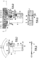
- the closure device shown in the figures consists essentially captive from one on the first component 2 lockable locking pin 4 and one at the back of the in this case frame-like second component 3 can be arranged housing-like receiving element 6, which by means a cage 7 on the back of the second component 3 is mountable.
- the locking pin 4 has one for the Support on the front 8 of the first component 2 as Countersunk head section 10, which in a corresponding sinking of a guide sleeve 16 fits, and one that can be passed through an opening 12 of the guide sleeve 16 Shaft section 18.
- the guide sleeve 16 is in an opening 14 of the first Component 2 inserted and also has a conical Countersunk head section 32, which in a corresponding front depression in the edge of the opening 14 of the first component 2 fits.
- the shaft section 18 of the locking pin 4 is partial hollow cylindrical and has a thread 24 on the inside, which with an outer counter thread 20 of a connecting section 22 of the receiving element 6 cooperates.
- the head section is actuated by means of a turning tool 10 of the locking pin 4 with a wing cross slot 44 fitted.
- the receiving section 6 supports the shaft section 18 its rear end face 50 on a spring assembly 52 in from the receiving element 6.
- the locking pin 4 can with its shaft portion 18 in the opening 12 of the guide sleeve 16 initially only so far be introduced until it is mated with a chamfer 46 provided stop edge 48 on an in an annular groove Recess 30 of the opening 12 of the guide sleeve 16 provided, as a clamping ring with a substantially rectangular flat cross section formed locking ring 28 is present.
- the shaft section 18 is pressed further into the Guide sleeve 16 is the locking ring 28 against it inward spring preload widened while doing so pressed deeper into the recess 30 until the bead-like stop edge 48 slid past the locking ring 28 is.
- the spring preload is dimensioned so that the Locking pin 4 remains in any axial position.
- the guide sleeve 16 has, as previously mentioned, on its Head portion 10 of the locking pin 16 facing away from the end a radially expandable collar-like fastening section 34 relatively small wall thickness, which is initially in is essentially cylindrical and if necessary under assembly Liner of a washer 36 using a Deforming tool is bent outwards all around.
- the Flanging tool can be with a threaded pin in the Engage internal thread 24 of the shaft section 18.
- the guide sleeve 16 includes the shaft portion 18 of the Locking pin 4 in the area of the shear gap S between the first component 2 and the second component 3 without play or in essentially free of play, in an area of otherwise formed as a hollow pin 4, in which of these between the wing cross slot 44 and the Threaded bore 54 of the hollow cylindrical part of the shaft section 18 is designed as a full stock.
- Drive depth of the cross wedge slot 44 and depth of the threaded bore 54 are at maximum demand on drive cycles and maximum Requirement for thread overlap so coordinated that with minimum thickness of the first component 2 due to the remaining full shaft section maximum shear stress is guaranteed.
- the guide sleeve 16 which is slightly thicker than the first Component 2 has between its rear end face 40 and the fastening section 34 has an annular recess 42 on so that the mounting portion 34, which in a Plane E perpendicular to the axis A of the guide sleeve 16 radially is angled outwards, despite the form-fitting Overlap the washer 36 taking into account Tolerances in the material thickness of the first component 2 die End face 40 of the guide sleeve 16 is not significant towered over.
- the washer 36 is flat in cross section in essentially formed rectangular ring disc and surrounds the guide sleeve 16 free of play or essentially free of play.
- the fastening section 34 is perpendicular in the plane E. to the axis A of the guide sleeve 16 across the flat Washer 36 so that excessive pressure forces on the Edge of the first component 2 can be avoided.
- the fastening section 34 can have a wall thickness between 0.1 and 3 mm, the washer 36 a material thickness D have between 0.2 and 0.5 mm, so that on the one hand guarantees is that the mounting portion 34 the washer 36, which with a radius R is rounded, encompassing form-fitting, during assembly can be turned outwards using a tool, on the other hand, the required shear and tensile strength is guaranteed.
- the fastening section 34 can rather an angle of more than 90 ° in a countersink in which the Guide sleeve 16 surrounding edge of the back 38 of the first Component 2 be flanged to the outside to accommodate Improve shear forces.
- Figure 4 illustrates a section of a first component 2 in the area of the opening 14, which in this case also a back depression 56, within which the Fastening section 34 can be flanged less than 90 ° can.
- Such an embodiment is suitable for components 2 a non-delaminating material such as aluminum.
Applications Claiming Priority (2)
| Application Number | Priority Date | Filing Date | Title |
|---|---|---|---|
| DE19731038A DE19731038C2 (de) | 1997-07-18 | 1997-07-18 | Verschlußeinrichtung |
| DE19731038 | 1997-07-18 |
Publications (3)
| Publication Number | Publication Date |
|---|---|
| EP0892178A2 true EP0892178A2 (fr) | 1999-01-20 |
| EP0892178A3 EP0892178A3 (fr) | 2000-02-23 |
| EP0892178B1 EP0892178B1 (fr) | 2002-10-09 |
Family
ID=7836241
Family Applications (1)
| Application Number | Title | Priority Date | Filing Date |
|---|---|---|---|
| EP98112012A Expired - Lifetime EP0892178B1 (fr) | 1997-07-18 | 1998-06-30 | Organe de verrouillage |
Country Status (3)
| Country | Link |
|---|---|
| US (1) | US6135690A (fr) |
| EP (1) | EP0892178B1 (fr) |
| DE (3) | DE19731038C2 (fr) |
Families Citing this family (2)
| Publication number | Priority date | Publication date | Assignee | Title |
|---|---|---|---|---|
| DE20313241U1 (de) * | 2003-08-27 | 2004-12-30 | Schwarzbich, Jörg | Vorrichtung zum Verbinden von Bauteilen mit Blindnietbefestigung |
| US20070160178A1 (en) * | 2006-01-11 | 2007-07-12 | Eaton Corporation | Electrical enclosure, structural assembly, and insert therefor |
Citations (6)
| Publication number | Priority date | Publication date | Assignee | Title |
|---|---|---|---|---|
| DE2142488A1 (de) * | 1970-09-03 | 1972-03-09 | Dzus Fastener Europe | Lösbarer Schraubverbinddr, insbesondere zum Anschluß von Tafeln an Rahmen od. dgl |
| DE2243661A1 (de) * | 1972-01-05 | 1973-07-19 | Deutsch Fastener Corp | Beschlag zur loesbaren befestigung eines bauteiles, insbesondere einer platte oder dgl. an einem anderen bauteil |
| DE3734735A1 (de) * | 1986-10-14 | 1988-04-21 | Avibank Mfg | Unverlierbare befestigungseinrichtungen fuer verkleidungen |
| DE3729423A1 (de) * | 1987-09-03 | 1989-03-16 | Camloc Gmbh | Verschlusseinrichtung zum verbinden plattenfoermiger bauteile |
| EP0480866A2 (fr) * | 1990-10-09 | 1992-04-15 | Vsi Corporation | Elément de fixation pour panneux à filet interne et ayant un anneau de soutien garantissant une force de soutien maximale |
| DE4032594C2 (de) * | 1990-10-13 | 1995-03-16 | Camloc Gmbh | Verschlußeinrichtung zum Verbinden zweier Bauteile |
Family Cites Families (6)
| Publication number | Priority date | Publication date | Assignee | Title |
|---|---|---|---|---|
| US4324517A (en) * | 1980-06-16 | 1982-04-13 | Sps Technologies, Inc. | Panel fastener assembly with retainer ring |
| US4735536A (en) * | 1986-09-26 | 1988-04-05 | Avibank Mfg., Inc. | Captive panel fastener assembly and method for installing the same |
| US4906153A (en) * | 1986-10-02 | 1990-03-06 | Avibank Mfg., Inc. | Captive panel fastener assembly |
| US4884930A (en) * | 1987-09-03 | 1989-12-05 | Camloc Gmbh | Panel fastener with friction cones |
| US5006025A (en) * | 1989-12-13 | 1991-04-09 | Avibank Mfg., Inc. | Self-locking nut |
| DE19608948A1 (de) * | 1996-03-11 | 1997-09-18 | Camloc Gmbh | Führungshülse |
-
1997
- 1997-07-18 DE DE19731038A patent/DE19731038C2/de not_active Expired - Fee Related
- 1997-08-06 DE DE29714014U patent/DE29714014U1/de not_active Expired - Lifetime
-
1998
- 1998-06-30 DE DE59805876T patent/DE59805876D1/de not_active Expired - Lifetime
- 1998-06-30 EP EP98112012A patent/EP0892178B1/fr not_active Expired - Lifetime
- 1998-07-17 US US09/116,765 patent/US6135690A/en not_active Expired - Fee Related
Patent Citations (6)
| Publication number | Priority date | Publication date | Assignee | Title |
|---|---|---|---|---|
| DE2142488A1 (de) * | 1970-09-03 | 1972-03-09 | Dzus Fastener Europe | Lösbarer Schraubverbinddr, insbesondere zum Anschluß von Tafeln an Rahmen od. dgl |
| DE2243661A1 (de) * | 1972-01-05 | 1973-07-19 | Deutsch Fastener Corp | Beschlag zur loesbaren befestigung eines bauteiles, insbesondere einer platte oder dgl. an einem anderen bauteil |
| DE3734735A1 (de) * | 1986-10-14 | 1988-04-21 | Avibank Mfg | Unverlierbare befestigungseinrichtungen fuer verkleidungen |
| DE3729423A1 (de) * | 1987-09-03 | 1989-03-16 | Camloc Gmbh | Verschlusseinrichtung zum verbinden plattenfoermiger bauteile |
| EP0480866A2 (fr) * | 1990-10-09 | 1992-04-15 | Vsi Corporation | Elément de fixation pour panneux à filet interne et ayant un anneau de soutien garantissant une force de soutien maximale |
| DE4032594C2 (de) * | 1990-10-13 | 1995-03-16 | Camloc Gmbh | Verschlußeinrichtung zum Verbinden zweier Bauteile |
Also Published As
| Publication number | Publication date |
|---|---|
| EP0892178B1 (fr) | 2002-10-09 |
| DE19731038C2 (de) | 2002-06-20 |
| DE29714014U1 (de) | 1997-11-06 |
| EP0892178A3 (fr) | 2000-02-23 |
| DE59805876D1 (de) | 2002-11-14 |
| US6135690A (en) | 2000-10-24 |
| DE19731038A1 (de) | 1999-02-11 |
Similar Documents
| Publication | Publication Date | Title |
|---|---|---|
| DE3734735C2 (de) | Unverlierbare Befestigungseinrichtungen für Verkleidungen | |
| DE4033763C2 (de) | Vorrichtung zum Sichern einer in einer Öffnung in einer Verkleidung aufgenommenen Mutter | |
| DE3003908C2 (de) | Stehbolzen mit Stanz- und Nietverhalten | |
| DE2008035C3 (fr) | ||
| DE4039472C2 (de) | Vorrichtung zum Sichern einer in einer Öffnung einer Verkleidung aufgenommenen Mutter | |
| EP1696138B1 (fr) | Dispositif de compensation de tolérance | |
| EP0487890A1 (fr) | Jonction d'élément, en particulier d'un joint à brides | |
| DE2700665A1 (de) | Befestiger-satz zum verbinden einer zusammengesetzten platte o.dgl. mit einem rahmenabschnitt | |
| DE3732521C2 (de) | Unverlierbare Befestigungseinrichtung für Verkleidungen und Verfahren für deren Montage | |
| EP3309414B1 (fr) | Élément de fonction pour fixation étanche aux fluides sur une pièce de tôlerie, ensemble de montage et procédé | |
| DE3735250A1 (de) | Schnellbefestigungseinrichtung | |
| EP2857699B1 (fr) | Douille taraudée à visser | |
| DE3420696C1 (de) | Klemmbeschlag für die Befestigung und/oder Verbindung von Glasscheiben, insbesondere für Fassadenplatten aus Einscheibensicherheitsglas | |
| DE102013222444B4 (de) | Befestigungsvorrichtung und Verfahren zum Befestigen von Elementen | |
| DE102010032866A1 (de) | Selbststanzendes Mutterelement und Zusammenbauteil bestehend aus dem Mutterelement und einem Blechteil | |
| DE102018117131A1 (de) | Selbststanzendes Element und Zusammenbauteil bestehend aus dem Element und einem Blechteil | |
| EP0859915B1 (fr) | Element de fixation | |
| DE3506127A1 (de) | Befestigungsvorrichtung fuer wenigstens zwei miteinander zu verbindende teile, vorzugsweise an kraftfahrzeugen | |
| EP3199824A1 (fr) | Système de fixation et son utilisation | |
| EP0892178B1 (fr) | Organe de verrouillage | |
| DE10020218A1 (de) | Montageeinheit aus einem Bauteil und mindestens einer gewindeformenden Schraube | |
| DE4106507C2 (fr) | ||
| DE4003784C2 (fr) | ||
| DE1912996C3 (de) | Preßsitzverbindung von Bauteilen, insbesondere für Konstruktionen der Luftfahrtindustrie | |
| EP0616137B1 (fr) | Boulon de tension pour fournitures pour meubles |
Legal Events
| Date | Code | Title | Description |
|---|---|---|---|
| PUAI | Public reference made under article 153(3) epc to a published international application that has entered the european phase |
Free format text: ORIGINAL CODE: 0009012 |
|
| AK | Designated contracting states |
Kind code of ref document: A2 Designated state(s): DE FR GB IT SE |
|
| AX | Request for extension of the european patent |
Free format text: AL;LT;LV;MK;RO;SI |
|
| PUAL | Search report despatched |
Free format text: ORIGINAL CODE: 0009013 |
|
| AK | Designated contracting states |
Kind code of ref document: A3 Designated state(s): AT BE CH CY DE DK ES FI FR GB GR IE IT LI LU MC NL PT SE |
|
| AX | Request for extension of the european patent |
Free format text: AL;LT;LV;MK;RO;SI |
|
| 17P | Request for examination filed |
Effective date: 20000426 |
|
| AKX | Designation fees paid |
Free format text: DE FR GB IT SE |
|
| 17Q | First examination report despatched |
Effective date: 20010202 |
|
| GRAG | Despatch of communication of intention to grant |
Free format text: ORIGINAL CODE: EPIDOS AGRA |
|
| GRAG | Despatch of communication of intention to grant |
Free format text: ORIGINAL CODE: EPIDOS AGRA |
|
| GRAH | Despatch of communication of intention to grant a patent |
Free format text: ORIGINAL CODE: EPIDOS IGRA |
|
| GRAH | Despatch of communication of intention to grant a patent |
Free format text: ORIGINAL CODE: EPIDOS IGRA |
|
| GRAA | (expected) grant |
Free format text: ORIGINAL CODE: 0009210 |
|
| AK | Designated contracting states |
Kind code of ref document: B1 Designated state(s): DE FR GB IT SE |
|
| REG | Reference to a national code |
Ref country code: GB Ref legal event code: FG4D Free format text: NOT ENGLISH |
|
| REF | Corresponds to: |
Ref document number: 59805876 Country of ref document: DE Date of ref document: 20021114 |
|
| ET | Fr: translation filed | ||
| GBT | Gb: translation of ep patent filed (gb section 77(6)(a)/1977) |
Effective date: 20030203 |
|
| PLBE | No opposition filed within time limit |
Free format text: ORIGINAL CODE: 0009261 |
|
| STAA | Information on the status of an ep patent application or granted ep patent |
Free format text: STATUS: NO OPPOSITION FILED WITHIN TIME LIMIT |
|
| 26N | No opposition filed |
Effective date: 20030710 |
|
| PGFP | Annual fee paid to national office [announced via postgrant information from national office to epo] |
Ref country code: SE Payment date: 20060627 Year of fee payment: 9 |
|
| PGFP | Annual fee paid to national office [announced via postgrant information from national office to epo] |
Ref country code: IT Payment date: 20060630 Year of fee payment: 9 |
|
| EUG | Se: european patent has lapsed | ||
| PG25 | Lapsed in a contracting state [announced via postgrant information from national office to epo] |
Ref country code: SE Free format text: LAPSE BECAUSE OF NON-PAYMENT OF DUE FEES Effective date: 20070701 |
|
| PG25 | Lapsed in a contracting state [announced via postgrant information from national office to epo] |
Ref country code: IT Free format text: LAPSE BECAUSE OF NON-PAYMENT OF DUE FEES Effective date: 20070630 |
|
| REG | Reference to a national code |
Ref country code: FR Ref legal event code: PLFP Year of fee payment: 19 |
|
| REG | Reference to a national code |
Ref country code: FR Ref legal event code: PLFP Year of fee payment: 20 |
|
| PGFP | Annual fee paid to national office [announced via postgrant information from national office to epo] |
Ref country code: FR Payment date: 20170621 Year of fee payment: 20 Ref country code: GB Payment date: 20170626 Year of fee payment: 20 |
|
| PGFP | Annual fee paid to national office [announced via postgrant information from national office to epo] |
Ref country code: DE Payment date: 20170830 Year of fee payment: 20 |
|
| REG | Reference to a national code |
Ref country code: DE Ref legal event code: R071 Ref document number: 59805876 Country of ref document: DE |
|
| REG | Reference to a national code |
Ref country code: GB Ref legal event code: PE20 Expiry date: 20180629 |
|
| PG25 | Lapsed in a contracting state [announced via postgrant information from national office to epo] |
Ref country code: GB Free format text: LAPSE BECAUSE OF EXPIRATION OF PROTECTION Effective date: 20180629 |