EP0892138A2 - Ferrure avec une têtière pour une porte ou une fenêtre - Google Patents
Ferrure avec une têtière pour une porte ou une fenêtre Download PDFInfo
- Publication number
- EP0892138A2 EP0892138A2 EP98109589A EP98109589A EP0892138A2 EP 0892138 A2 EP0892138 A2 EP 0892138A2 EP 98109589 A EP98109589 A EP 98109589A EP 98109589 A EP98109589 A EP 98109589A EP 0892138 A2 EP0892138 A2 EP 0892138A2
- Authority
- EP
- European Patent Office
- Prior art keywords
- faceplate
- holder
- receiving groove
- door
- legs
- Prior art date
- Legal status (The legal status is an assumption and is not a legal conclusion. Google has not performed a legal analysis and makes no representation as to the accuracy of the status listed.)
- Granted
Links
Images


Classifications
-
- E—FIXED CONSTRUCTIONS
- E05—LOCKS; KEYS; WINDOW OR DOOR FITTINGS; SAFES
- E05C—BOLTS OR FASTENING DEVICES FOR WINGS, SPECIALLY FOR DOORS OR WINDOWS
- E05C9/00—Arrangements of simultaneously actuated bolts or other securing devices at well-separated positions on the same wing
- E05C9/004—Faceplates ; Fixing the faceplates to the wing
Definitions
- the invention relates to a faceplate fitting according to the preamble of claim 1.
- the faceplate fitting is intended to be an immovable fixed Get seat by the cold, the holder with Knurling or the like, which on the boundary walls the receiving groove assigned outer edges are arranged in dig in the sash frame material.
- the necessary Force is obtained by tightening the fastening screws upset. A subsequent adjustment of the fitting after tightening the fastening screws is no longer possible and not provided. Also are for attachment or fixation with cold tools necessary.
- the tongues are alternately in the longitudinal direction in the provided different lengths and in relation to whose longitudinal dimensions are thin-walled.
- the invention is therefore based on DE 31 01 393 C2 based on the task of a screwless and detachable nevertheless sufficiently strong attachment or fixation without to allow additional tooling at any Profileing applies regardless of whether the Have receiving grooves webs or the like.
- the fixation should allow longitudinal movement of the component.
- the cold causes a problem-free and tool-free Fasten a drive rod fitting component equipped with it.
- the component can be - for subsequent coupling or the like - move along the receiving groove, but is on the wing fixed in a way that a displacement of the Wing and the subsequent fastening with Fasteners allowed. It is also achieved that the achievable frictional engagement is maximized because of the resilient acting legs designed stable and one if possible have a large friction surface, but at the same time a possibility for elastic deformation.
- the resiliently designed legs allow that Fixing the hardware parts in almost all conceivable Profiling and dimensional configurations of the receiving groove.
- a non-rotatable connection of the holder to the faceplate is achieved in that the cold in its upper, the Cross-section assigned rectangular or rectangular is square.
- the torsion bar which is under pressure, will twist thereby preventing the legs of the holder from Support the connecting rod against the ground.
- Fig. 1 shows a faceplate fitting 1, which in a Receiving groove 2 of a wing profile 3 attached or fixed shall be.
- the faceplate fitting 1 consists of a Forend rail 5 and one of which is longitudinally displaceable Driving rod 6, and a cold 7, which is fixed to the Face plate 5 is connected.
- the cold 7 is - in Considered longitudinal direction of the receiving groove 2 - W or V-shaped formed, the opening of the cross section for Forend rail 5 or drive rod 6 in the opening direction the receiving groove points.
- the free legs 8 therefore run in Direction of the faceplate 5 apart.
- the maximum Distance dimension 10 of the outer edges of the legs 8 arises therefore near the free end 9 of the leg 8.
- the dimension 10 is dimensioned larger than the dimension 11 between the Boundary walls 12 of the receiving groove 2.
- the free legs 8 of the holder 7 are in one piece with the Holder formed and consist of an elastic deformable material - for example plastic or Metal - and are therefore designed to be resilient.
- the entire holder 7 is preferably in one piece as Plastic molded part.
- the width 14 is dimensioned somewhat larger than the width 18 of the faceplate 5 whose step height 19 of the faceplate thickness 20 is adapted.
- the faceplate 5 is therefore supported over its entire length on level 15 and on the other hand by the holder 7th at least in some areas also against the bottom 21 of the Supporting groove 2 supported, as can be seen from Fig. 2. It it is also clear here that the free leg 8 of the Holder 7 due to the smaller size 11 of the receiving groove 2nd elastic when inserting the faceplate fitting 1 be deformed and are therefore inclined inwards.
- the legs 8 are resilient, to the lateral boundary walls 12 of the receiving groove 2 range and in this case, at least in some areas, plan on them, arises from the cold 7 against the opening direction and along the receiving groove 2 acting friction, the one Fixation until final attachment, for example with Fasteners represents.
- the cold 7 extends through an elongated hole in the drive rod 6 and is fixedly connected to the drive rod 5.
- Fig. 3 shows the holder 7 in a receiving groove 2
- the step 15 is formed by webs 23 by retreating the boundary walls 12 in the lower region of the receiving groove 2 arise.
- the receiving groove 2 is therefore in the lower part relative to the walls of the receiving groove according to FIGS. 1 and 2 broadened.
- the holder 7 cooperates with the legs 8 the webs 23 together, the boundary walls 12 of the Form the groove in the upper area.
- the cold 7 causes here also a frictional connection with these as boundary walls 12 acting webs 23 in the form that by the spring-elastic leg 8, when inserted into the receiving groove is energized, flat on the webs 23 is present and causes a frictional connection with them.
- a Removing the faceplate fitting 1 from the receiving groove 2 is therefore still possible.
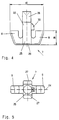
- FIGS. 4 and 5 show the embodiment of the holder 7 in unmounted condition.
- the cold 7 is, as in particular, from 1 to 3 and Fig. 5 becomes clear in the assembled Condition of the faceplate fitting 1 essentially across aligned with the receiving groove 2.
- the axis of symmetry 24 of the holder 7 therefore runs transverse to Longitudinal axis of the receiving groove 2, the holder 7 according to FIG. 5 - viewed from above - appears cruciform.
- the the Section 25 connecting leg 25 has a vertical Fastening approach 22 on the cold 7 a W-shaped Gives cross section.
- the attachment boss 22 is in his Main dimension offset by 90 ° to section 25 aligned and protrudes with its upper free end in the Face plate 5, which is not shown here.
- the Cross section rectangular or square and in the final assembly position of the faceplate 5 is assigned.
- the Face plate 5 lies on the shoulders 27 of the Attachment approach 22.
- the approach 26 Through plastic deformation the upper one, in the assembly position through the faceplate 5 protruding end of the attachment projection 22, the approach 26, the cold 7 is therefore firm and immovable - by the Engagement of the rectangular cross section 26 'is also non-rotatable connected to the faceplate 5.
- the cold 7 is designed flat on the underside 28, so that the holder 7 after assembly of the faceplate fitting 1 lies flat on the bottom 21 of the receiving groove 2, like the 2 and 3 show.
- the interpretation of the height 29 of the legs 8 takes place - taking into account the strength of the Driving rod 6 - so that the legs 8 even at one 3 always with the boundary walls 12 Have contact, as can also be seen in FIG. 4.
- the legs 8 are square or rectangular in the rectangle formed, the legs 8 in the initial state - outside the receiving groove 2 - on the facing each other Side almost perpendicular to the faceplate 5 or Attachment approach 25 run.
- the averted Sides of the legs 8 at least move away in regions from each other, creating the V-shaped cross section the outer contour is created.
- the Nose 30 is due to the limitations of the side Recesses of the slot in a known manner sheared.
- the holder 7 achieve a fixation of the faceplate fitting 1. This is necessary because modern window production systems in work several, but at least on two levels.
- a First level the fittings are in the receiving groove 2 inserted and fixed by the cold 7.
- the the Faceplate fitting 7 bearing wing is in its plane rotated so that the fixed fitting part of the Faceplate fitting 1 reaches the second level. While additional fittings are coupled on the first level, the final attachment can already be made on the second level of the faceplate fitting 1, e.g. by means of partial or fully automatic screwdriver.
- the fixing of the faceplate fitting 1 by the holder 7 is therefore primarily used for a preliminary attachment to the Sash - without the fittings from the mounting groove 2 fall out - can be rotated and / or moved.
- Fitting parts of the faceplate fitting 1, which in Corner area of the wing are arranged and therefore in both Layers protrude simultaneously before the final one To be able to move the fastening along the receiving groove 2, for example for or after coupling with others Fitting parts of the faceplate fitting 1, can Displacement can be made along the receiving groove 2.
- the cold can be used with all wing materials and that at If necessary, several brackets must be attached to a faceplate can.
Landscapes
- Engineering & Computer Science (AREA)
- Mechanical Engineering (AREA)
- Specific Sealing Or Ventilating Devices For Doors And Windows (AREA)
- Window Of Vehicle (AREA)
- Wing Frames And Configurations (AREA)
- Closing And Opening Devices For Wings, And Checks For Wings (AREA)
- Support Devices For Sliding Doors (AREA)
- Power-Operated Mechanisms For Wings (AREA)
Applications Claiming Priority (2)
| Application Number | Priority Date | Filing Date | Title |
|---|---|---|---|
| DE19730600 | 1997-07-17 | ||
| DE19730600A DE19730600A1 (de) | 1997-07-17 | 1997-07-17 | Stulpschienenbeschlag |
Publications (3)
| Publication Number | Publication Date |
|---|---|
| EP0892138A2 true EP0892138A2 (fr) | 1999-01-20 |
| EP0892138A3 EP0892138A3 (fr) | 1999-06-30 |
| EP0892138B1 EP0892138B1 (fr) | 2002-04-10 |
Family
ID=7835966
Family Applications (1)
| Application Number | Title | Priority Date | Filing Date |
|---|---|---|---|
| EP98109589A Expired - Lifetime EP0892138B1 (fr) | 1997-07-17 | 1998-05-27 | Ferrure avec une têtière pour une porte ou une fenêtre |
Country Status (5)
| Country | Link |
|---|---|
| EP (1) | EP0892138B1 (fr) |
| AT (1) | ATE216019T1 (fr) |
| DE (2) | DE19730600A1 (fr) |
| DK (1) | DK0892138T3 (fr) |
| ES (1) | ES2175551T3 (fr) |
Cited By (6)
| Publication number | Priority date | Publication date | Assignee | Title |
|---|---|---|---|---|
| EP0937847A1 (fr) * | 1998-02-24 | 1999-08-25 | Gretsch-Unitas GmbH Baubeschläge | Têtière à fixer dans une gorge de ferrure, notamment pour recouvrir une tringle de manoeuvre de porte, fenêtre ou similaire en au moins une partie |
| EP1099819A2 (fr) * | 1999-11-12 | 2001-05-16 | Roto Frank Ag | Ensemble de ferrure pour montage sur une fenêtre, une porte, ou similaire et procédé de fabrication d'un tel ensemble |
| AT505010B1 (de) * | 2007-06-15 | 2008-10-15 | Drutex S A | Fenster- oder türhohlprofil |
| EP2058463A3 (fr) * | 2007-11-08 | 2011-01-05 | Aug. Winkhaus GmbH & Co. KG | Renvoi d'angle pour un système d'armature de tige motrice pour un vantail de fenêtre ou de porte |
| CN103899144A (zh) * | 2014-04-15 | 2014-07-02 | 李健 | 一种平开门锁座 |
| DE102019200158A1 (de) | 2019-01-09 | 2020-07-09 | Aug. Winkhaus Gmbh & Co. Kg | Halteelement eines beschlagteils eines treibstangenbeschlages |
Families Citing this family (7)
| Publication number | Priority date | Publication date | Assignee | Title |
|---|---|---|---|---|
| DE19923434B4 (de) * | 1999-05-21 | 2005-11-03 | Bayerwald Fenster-Türen Altenbuchinger GmbH & Co. KG | Vorrichtung zur Befestigung einer Beschlagleiste an einem Profil |
| DE10008733A1 (de) | 2000-02-24 | 2001-08-30 | Aubi Baubeschlaege Gmbh | Beschlag für ein Fenster oder eine Tür |
| DE10012735B4 (de) * | 2000-03-16 | 2013-07-04 | Roto Frank Ag | Beschlag an einem Flügel oder einem festen Rahmen eines Fensters, einer Tür oder dergleichen |
| DE102008041083A1 (de) | 2008-08-07 | 2010-02-11 | Aug. Winkhaus Gmbh & Co. Kg | Beschlagteil eines Treibstangenbeschlages |
| FR2938888B1 (fr) * | 2008-11-27 | 2010-12-10 | Metalux | Dispositif de fixation de tetiere. |
| DE202009014693U1 (de) * | 2009-10-30 | 2011-03-17 | MACO Vermögensverwaltung GmbH | Beschlaganordnung |
| DE202018000164U1 (de) | 2018-01-12 | 2018-03-05 | Siegenia-Aubi Kg | Beschlag oder Beschlagteil mit einem Klemmteil |
Citations (3)
| Publication number | Priority date | Publication date | Assignee | Title |
|---|---|---|---|---|
| DE2407196A1 (de) | 1974-02-15 | 1975-08-28 | Bilstein August Fa | Treibstangenbeschlag fuer fenster, tueren o.dgl., insbesondere kunststoff-fluegelrahmen |
| DE3101393A1 (de) | 1981-01-17 | 1982-09-02 | SCHÜCO Heinz Schürmann GmbH & Co, 4800 Bielefeld | "mit einem stulpschienenbeschlag ausgeruesteter tuer- oder fensterfluegel" |
| DE19646988A1 (de) | 1996-11-14 | 1998-05-20 | Roto Frank Ag | Beschlag für ein Fenster |
Family Cites Families (2)
| Publication number | Priority date | Publication date | Assignee | Title |
|---|---|---|---|---|
| DE1884854U (de) * | 1961-01-26 | 1963-12-19 | Gretsch Unifas G M B H | Einstellbarer verriegelungszapfen fuer tuer- und fensterverschluesse. |
| DE29514640U1 (de) * | 1995-09-12 | 1995-11-23 | Aug. Winkhaus GmbH & Co. KG, 48291 Telgte | Treibstangenbeschlag für Türen, Fenster o.dgl. |
-
1997
- 1997-07-17 DE DE19730600A patent/DE19730600A1/de not_active Withdrawn
-
1998
- 1998-05-27 AT AT98109589T patent/ATE216019T1/de active
- 1998-05-27 EP EP98109589A patent/EP0892138B1/fr not_active Expired - Lifetime
- 1998-05-27 DK DK98109589T patent/DK0892138T3/da active
- 1998-05-27 DE DE59803696T patent/DE59803696D1/de not_active Expired - Lifetime
- 1998-05-27 ES ES98109589T patent/ES2175551T3/es not_active Expired - Lifetime
Patent Citations (3)
| Publication number | Priority date | Publication date | Assignee | Title |
|---|---|---|---|---|
| DE2407196A1 (de) | 1974-02-15 | 1975-08-28 | Bilstein August Fa | Treibstangenbeschlag fuer fenster, tueren o.dgl., insbesondere kunststoff-fluegelrahmen |
| DE3101393A1 (de) | 1981-01-17 | 1982-09-02 | SCHÜCO Heinz Schürmann GmbH & Co, 4800 Bielefeld | "mit einem stulpschienenbeschlag ausgeruesteter tuer- oder fensterfluegel" |
| DE19646988A1 (de) | 1996-11-14 | 1998-05-20 | Roto Frank Ag | Beschlag für ein Fenster |
Cited By (10)
| Publication number | Priority date | Publication date | Assignee | Title |
|---|---|---|---|---|
| EP0937847A1 (fr) * | 1998-02-24 | 1999-08-25 | Gretsch-Unitas GmbH Baubeschläge | Têtière à fixer dans une gorge de ferrure, notamment pour recouvrir une tringle de manoeuvre de porte, fenêtre ou similaire en au moins une partie |
| EP1099819A2 (fr) * | 1999-11-12 | 2001-05-16 | Roto Frank Ag | Ensemble de ferrure pour montage sur une fenêtre, une porte, ou similaire et procédé de fabrication d'un tel ensemble |
| EP1099819A3 (fr) * | 1999-11-12 | 2002-12-18 | Roto Frank Ag | Ensemble de ferrure pour montage sur une fenêtre, une porte, ou similaire et procédé de fabrication d'un tel ensemble |
| AT505010B1 (de) * | 2007-06-15 | 2008-10-15 | Drutex S A | Fenster- oder türhohlprofil |
| WO2008152100A1 (fr) * | 2007-06-15 | 2008-12-18 | Drutex S.A. | Profilé creux de fenêtre ou de porte |
| EA014608B1 (ru) * | 2007-06-15 | 2010-12-30 | Друтекс С.А. | Оконный или дверной полый профиль |
| EP2058463A3 (fr) * | 2007-11-08 | 2011-01-05 | Aug. Winkhaus GmbH & Co. KG | Renvoi d'angle pour un système d'armature de tige motrice pour un vantail de fenêtre ou de porte |
| CN103899144A (zh) * | 2014-04-15 | 2014-07-02 | 李健 | 一种平开门锁座 |
| DE102019200158A1 (de) | 2019-01-09 | 2020-07-09 | Aug. Winkhaus Gmbh & Co. Kg | Halteelement eines beschlagteils eines treibstangenbeschlages |
| EP3683387A1 (fr) | 2019-01-09 | 2020-07-22 | Aug. Winkhaus GmbH & Co. KG | Élément de fixation d'une partie de ferrure d'une crémone |
Also Published As
| Publication number | Publication date |
|---|---|
| ES2175551T3 (es) | 2002-11-16 |
| DE19730600A1 (de) | 1999-01-21 |
| DE59803696D1 (de) | 2002-05-16 |
| DK0892138T3 (da) | 2002-07-01 |
| EP0892138A3 (fr) | 1999-06-30 |
| ATE216019T1 (de) | 2002-04-15 |
| EP0892138B1 (fr) | 2002-04-10 |
Similar Documents
| Publication | Publication Date | Title |
|---|---|---|
| EP0136431B1 (fr) | Ossature en profilés | |
| EP0892138B1 (fr) | Ferrure avec une têtière pour une porte ou une fenêtre | |
| WO1999041508A2 (fr) | Dispositif d'assemblage pour corps plats ou autres composants | |
| DE2313690A1 (de) | Treibstangenbeschlag fuer fenster, tueren od.dgl | |
| EP0582258B1 (fr) | Dispositif de fixation | |
| EP1840314B1 (fr) | Composant coupe-feu | |
| EP0937847A1 (fr) | Têtière à fixer dans une gorge de ferrure, notamment pour recouvrir une tringle de manoeuvre de porte, fenêtre ou similaire en au moins une partie | |
| EP1568838A2 (fr) | Rail de guidage pour portes coulissantes ou portes coulissantes et pliantes | |
| EP3859105A1 (fr) | Dispositif de fermeture | |
| CH657179A5 (de) | System zur fuehrung und fixierung von beschlaegen an tueren oder fenstern. | |
| DE19740603C2 (de) | Stulpschienenbefestigung | |
| DE20019594U1 (de) | Justiervorrichtung eines Rahmens | |
| EP0731282B1 (fr) | Elément de fixation | |
| EP3535824B1 (fr) | Support de jeu de barres et ensemble correspondant | |
| DE10012729A1 (de) | Vorrichtung zum stirnseitigen Verbinden von Profilstäben | |
| DE19808847C2 (de) | Tür- oder Fensterbeschlag | |
| EP1469157B1 (fr) | Profil de verrouillage | |
| EP1216336B1 (fr) | Element de garniture | |
| EP2385200B1 (fr) | Elément de ferrure pour la fixation dans une rainure de ferrure en forme de C | |
| EP1002919B1 (fr) | Tringlerie de commande pour fenêtres, portes ou similaires | |
| DE4413747C2 (de) | Abdeckschiene zur Befestigung von Leuchten oder Leuchtenteilen | |
| DE20219174U1 (de) | Dichtung insbesondere selbsttätig absenkende Bodendichtung für Türen | |
| DE29704183U1 (de) | Einhängevorrichtung für eine Fassadenunterkonstruktion | |
| DE19734876A1 (de) | Verbindungselement zur Verbindung eines Hohlteils mit einem auf Stoß anliegenden Profilteil im Tür- oder Fensterbau | |
| EP1033294B1 (fr) | Dispositif de réglage en hauteur pour un ancrage de renvoi de ceinture de sécurité dans un véhicule á moteur |
Legal Events
| Date | Code | Title | Description |
|---|---|---|---|
| PUAI | Public reference made under article 153(3) epc to a published international application that has entered the european phase |
Free format text: ORIGINAL CODE: 0009012 |
|
| AK | Designated contracting states |
Kind code of ref document: A2 Designated state(s): AT BE CH DE DK ES FR GB IT LI NL |
|
| AX | Request for extension of the european patent |
Free format text: AL;LT;LV;MK;RO;SI |
|
| PUAL | Search report despatched |
Free format text: ORIGINAL CODE: 0009013 |
|
| AK | Designated contracting states |
Kind code of ref document: A3 Designated state(s): AT BE CH CY DE DK ES FI FR GB GR IE IT LI LU MC NL PT SE |
|
| AX | Request for extension of the european patent |
Free format text: AL;LT;LV;MK;RO;SI |
|
| 17P | Request for examination filed |
Effective date: 19990716 |
|
| AKX | Designation fees paid |
Free format text: AT BE CH DE DK ES FR GB IT LI NL |
|
| AXX | Extension fees paid |
Free format text: LT PAYMENT 19990716;SI PAYMENT 19990716 |
|
| GRAG | Despatch of communication of intention to grant |
Free format text: ORIGINAL CODE: EPIDOS AGRA |
|
| GRAG | Despatch of communication of intention to grant |
Free format text: ORIGINAL CODE: EPIDOS AGRA |
|
| GRAH | Despatch of communication of intention to grant a patent |
Free format text: ORIGINAL CODE: EPIDOS IGRA |
|
| 17Q | First examination report despatched |
Effective date: 20010912 |
|
| REG | Reference to a national code |
Ref country code: GB Ref legal event code: IF02 |
|
| GRAH | Despatch of communication of intention to grant a patent |
Free format text: ORIGINAL CODE: EPIDOS IGRA |
|
| GRAA | (expected) grant |
Free format text: ORIGINAL CODE: 0009210 |
|
| AK | Designated contracting states |
Kind code of ref document: B1 Designated state(s): AT BE CH DE DK ES FR GB IT LI NL |
|
| AX | Request for extension of the european patent |
Free format text: LT PAYMENT 19990716;SI PAYMENT 19990716 |
|
| PG25 | Lapsed in a contracting state [announced via postgrant information from national office to epo] |
Ref country code: NL Free format text: LAPSE BECAUSE OF FAILURE TO SUBMIT A TRANSLATION OF THE DESCRIPTION OR TO PAY THE FEE WITHIN THE PRESCRIBED TIME-LIMIT Effective date: 20020410 |
|
| REF | Corresponds to: |
Ref document number: 216019 Country of ref document: AT Date of ref document: 20020415 Kind code of ref document: T |
|
| REG | Reference to a national code |
Ref country code: CH Ref legal event code: EP |
|
| GBT | Gb: translation of ep patent filed (gb section 77(6)(a)/1977) |
Effective date: 20020410 |
|
| REG | Reference to a national code |
Ref country code: CH Ref legal event code: NV Representative=s name: PATENTANWAELTE GEORG ROEMPLER UND ALDO ROEMPLER |
|
| REF | Corresponds to: |
Ref document number: 59803696 Country of ref document: DE Date of ref document: 20020516 |
|
| PGFP | Annual fee paid to national office [announced via postgrant information from national office to epo] |
Ref country code: DK Payment date: 20020527 Year of fee payment: 5 Ref country code: BE Payment date: 20020527 Year of fee payment: 5 |
|
| REG | Reference to a national code |
Ref country code: DK Ref legal event code: T3 |
|
| ET | Fr: translation filed | ||
| NLV1 | Nl: lapsed or annulled due to failure to fulfill the requirements of art. 29p and 29m of the patents act | ||
| REG | Reference to a national code |
Ref country code: ES Ref legal event code: FG2A Ref document number: 2175551 Country of ref document: ES Kind code of ref document: T3 |
|
| LTIE | Lt: invalidation of european patent or patent extension |
Effective date: 20020410 |
|
| PLBE | No opposition filed within time limit |
Free format text: ORIGINAL CODE: 0009261 |
|
| STAA | Information on the status of an ep patent application or granted ep patent |
Free format text: STATUS: NO OPPOSITION FILED WITHIN TIME LIMIT |
|
| 26N | No opposition filed |
Effective date: 20030113 |
|
| RAP2 | Party data changed (patent owner data changed or rights of a patent transferred) |
Owner name: SIEGENIA-AUBI KG |
|
| REG | Reference to a national code |
Ref country code: CH Ref legal event code: PFA Owner name: SIEGENIA-AUBI KG Free format text: SIEGENIA-FRANK KG#EISENHUETTENSTRASSE 22#57074 SIEGEN (DE) -TRANSFER TO- SIEGENIA-AUBI KG#INDUSTRIESTRASSE 1-3#57234 WILNSDORF (DE) Ref country code: CH Ref legal event code: NV Representative=s name: PA ALDO ROEMPLER |
|
| PG25 | Lapsed in a contracting state [announced via postgrant information from national office to epo] |
Ref country code: BE Free format text: LAPSE BECAUSE OF NON-PAYMENT OF DUE FEES Effective date: 20030531 |
|
| BERE | Be: lapsed |
Owner name: *SIEGENIA-FRANK K.G. Effective date: 20030531 |
|
| PG25 | Lapsed in a contracting state [announced via postgrant information from national office to epo] |
Ref country code: DK Free format text: LAPSE BECAUSE OF NON-PAYMENT OF DUE FEES Effective date: 20031201 |
|
| REG | Reference to a national code |
Ref country code: DK Ref legal event code: EBP |
|
| REG | Reference to a national code |
Ref country code: CH Ref legal event code: PCAR Free format text: ALDO ROEMPLER PATENTANWALT;BRENDENWEG 11 POSTFACH 154;9424 RHEINECK (CH) |
|
| REG | Reference to a national code |
Ref country code: FR Ref legal event code: PLFP Year of fee payment: 19 |
|
| PGFP | Annual fee paid to national office [announced via postgrant information from national office to epo] |
Ref country code: DE Payment date: 20160531 Year of fee payment: 19 Ref country code: GB Payment date: 20160512 Year of fee payment: 19 Ref country code: CH Payment date: 20160512 Year of fee payment: 19 Ref country code: ES Payment date: 20160520 Year of fee payment: 19 |
|
| PGFP | Annual fee paid to national office [announced via postgrant information from national office to epo] |
Ref country code: FR Payment date: 20160512 Year of fee payment: 19 Ref country code: IT Payment date: 20160531 Year of fee payment: 19 Ref country code: AT Payment date: 20160516 Year of fee payment: 19 |
|
| REG | Reference to a national code |
Ref country code: DE Ref legal event code: R119 Ref document number: 59803696 Country of ref document: DE |
|
| REG | Reference to a national code |
Ref country code: CH Ref legal event code: PL |
|
| REG | Reference to a national code |
Ref country code: AT Ref legal event code: MM01 Ref document number: 216019 Country of ref document: AT Kind code of ref document: T Effective date: 20170527 |
|
| GBPC | Gb: european patent ceased through non-payment of renewal fee |
Effective date: 20170527 |
|
| PG25 | Lapsed in a contracting state [announced via postgrant information from national office to epo] |
Ref country code: AT Free format text: LAPSE BECAUSE OF NON-PAYMENT OF DUE FEES Effective date: 20170527 |
|
| PG25 | Lapsed in a contracting state [announced via postgrant information from national office to epo] |
Ref country code: CH Free format text: LAPSE BECAUSE OF NON-PAYMENT OF DUE FEES Effective date: 20170531 Ref country code: LI Free format text: LAPSE BECAUSE OF NON-PAYMENT OF DUE FEES Effective date: 20170531 |
|
| REG | Reference to a national code |
Ref country code: FR Ref legal event code: ST Effective date: 20180131 |
|
| PG25 | Lapsed in a contracting state [announced via postgrant information from national office to epo] |
Ref country code: DE Free format text: LAPSE BECAUSE OF NON-PAYMENT OF DUE FEES Effective date: 20171201 Ref country code: GB Free format text: LAPSE BECAUSE OF NON-PAYMENT OF DUE FEES Effective date: 20170527 |
|
| PG25 | Lapsed in a contracting state [announced via postgrant information from national office to epo] |
Ref country code: FR Free format text: LAPSE BECAUSE OF NON-PAYMENT OF DUE FEES Effective date: 20170531 Ref country code: IT Free format text: LAPSE BECAUSE OF NON-PAYMENT OF DUE FEES Effective date: 20170527 |
|
| REG | Reference to a national code |
Ref country code: ES Ref legal event code: FD2A Effective date: 20180620 |
|
| PG25 | Lapsed in a contracting state [announced via postgrant information from national office to epo] |
Ref country code: ES Free format text: LAPSE BECAUSE OF NON-PAYMENT OF DUE FEES Effective date: 20170528 |