EP0890379A1 - Skibindung - Google Patents
Skibindung Download PDFInfo
- Publication number
- EP0890379A1 EP0890379A1 EP98810645A EP98810645A EP0890379A1 EP 0890379 A1 EP0890379 A1 EP 0890379A1 EP 98810645 A EP98810645 A EP 98810645A EP 98810645 A EP98810645 A EP 98810645A EP 0890379 A1 EP0890379 A1 EP 0890379A1
- Authority
- EP
- European Patent Office
- Prior art keywords
- ski
- shoe
- transverse axis
- curve
- heel
- Prior art date
- Legal status (The legal status is an assumption and is not a legal conclusion. Google has not performed a legal analysis and makes no representation as to the accuracy of the status listed.)
- Granted
Links
- 230000027455 binding Effects 0.000 title claims description 81
- 238000009739 binding Methods 0.000 title claims description 81
- 238000005096 rolling process Methods 0.000 description 24
- 230000036961 partial effect Effects 0.000 description 14
- 230000009194 climbing Effects 0.000 description 9
- 230000006835 compression Effects 0.000 description 5
- 238000007906 compression Methods 0.000 description 5
- 210000002683 foot Anatomy 0.000 description 4
- 230000001174 ascending effect Effects 0.000 description 3
- 210000003484 anatomy Anatomy 0.000 description 2
- 230000008901 benefit Effects 0.000 description 2
- 239000010985 leather Substances 0.000 description 2
- 230000009471 action Effects 0.000 description 1
- 210000003423 ankle Anatomy 0.000 description 1
- 230000000903 blocking effect Effects 0.000 description 1
- 230000008859 change Effects 0.000 description 1
- 238000006073 displacement reaction Methods 0.000 description 1
- 230000000670 limiting effect Effects 0.000 description 1
- 238000004091 panning Methods 0.000 description 1
- 230000002829 reductive effect Effects 0.000 description 1
- 230000000284 resting effect Effects 0.000 description 1
- 230000002441 reversible effect Effects 0.000 description 1
- 230000007704 transition Effects 0.000 description 1
Images





Classifications
-
- A—HUMAN NECESSITIES
- A63—SPORTS; GAMES; AMUSEMENTS
- A63C—SKATES; SKIS; ROLLER SKATES; DESIGN OR LAYOUT OF COURTS, RINKS OR THE LIKE
- A63C9/00—Ski bindings
- A63C9/02—Non-self-releasing bindings with swivel sole-plate or swivel parts, i.e. Ellefsen-type
-
- A—HUMAN NECESSITIES
- A63—SPORTS; GAMES; AMUSEMENTS
- A63C—SKATES; SKIS; ROLLER SKATES; DESIGN OR LAYOUT OF COURTS, RINKS OR THE LIKE
- A63C9/00—Ski bindings
- A63C9/08—Ski bindings yieldable or self-releasing in the event of an accident, i.e. safety bindings
- A63C9/0807—Ski bindings yieldable or self-releasing in the event of an accident, i.e. safety bindings for both towing and downhill skiing
-
- A—HUMAN NECESSITIES
- A63—SPORTS; GAMES; AMUSEMENTS
- A63C—SKATES; SKIS; ROLLER SKATES; DESIGN OR LAYOUT OF COURTS, RINKS OR THE LIKE
- A63C9/00—Ski bindings
- A63C9/08—Ski bindings yieldable or self-releasing in the event of an accident, i.e. safety bindings
- A63C9/081—Ski bindings yieldable or self-releasing in the event of an accident, i.e. safety bindings with swivel sole-plate
Definitions
- the present invention relates to a ski binding.
- the invention relates a touring binding that ensures an ergonomic movement while walking Has curve body.
- ski bindings can be divided into slope bindings that only used for skiing and skiing on ski lifts, and touring bindings that in addition also for walking on skis, especially for ascending with the help of climbing skins attached to the skis can be used. While the former is just a reliable one Fixing the ski boot on the ski in a so-called downhill position to guarantee, the latter must also climb from the departure position can be brought into an ascending position of the binding, in which the ski boot mostly only in the area of the ski boot tip around a transverse axis is pivotally attached to the ski and can be lifted off the ski in the heel area to allow a joint movement between the ski boot and ski for walking.
- ski touring boots Since the advent of plastic ski boots, however, ski tourers have also been no longer ready for the much greater hold and the resulting better ski guidance to waive on departure. accessible with ski touring boots made of plastic are.
- Such Tour binding which in particular also all safety requirements modern slope bindings are described in WO 96/23559 (Fritschi). Ski bindings of this type are typically horizontal in the ascent position Cross axis swiveling in the area of the toe.
- this walking accessory allows a certain approach to a natural movement, he points out firstly, the disadvantage that the transition of joint movement from one Swivel movement around the first transverse axis to a swivel movement around the second transverse axis occurs abruptly, which is a jerky change in the course of motion for the skier, causing a slap on the shin with every step and / or the heel is transmitted.
- Second is the design-related binding height and consequently the height of the shoe position above the ski is considerable.
- the walking accessory for the departure must be removed from the binding and separately be carried along.
- the object of the present invention is to provide a ski binding by which overcome the disadvantages of the known ski bindings.
- the ski binding according to the invention has means for fastening a shoe to the Binding that is pivotally attached to the ski by at least one transverse axis are.
- the ski binding according to the invention has an articulated movement between the shoe fasteners and the cam steering cam body with a surface convexly curved in at least one area in the longitudinal direction of the ski on.
- cam body has its guiding function for joint movement at all the hinge between shoe fasteners and skis must of course have more than just one (degree of freedom) of freedom, as a swivel joint with exactly one degree of freedom of rotation, as is common with known touring bindings is a circular movement, the path of which is no longer controlled additionally can.
- a hinge that on the one hand allows the shoe fasteners around a transverse axis to be pivotably attached to the ski, and on the other hand more than just one (rotating) Degree of freedom, e.g. on a double joint with two swivel axes, a rotary-thrust joint, a curve joint, etc. are based.
- the cam body according to the invention controls the joint movement by means of a rolling process between the convexly curved surface and a counter surface.
- the rolling process between the convex curved surface in the longitudinal direction of the ski defines a rolling or rolling curve, and the counter surface can be made from one pure, non-slip rolling or rolling or a rolling combined with sliding consist.
- ski binding is not mistakenly so in the following understand that a ski binding can only be mounted on skis. Under Rather, ski binding is understood to mean a binding that, in addition to being attached to slopes and touring skis on all other types of skis, snowboards, big feet, Snowshoes, roller skis, skate runners and similar devices can be attached, that require a flexible connection between a shoe and the device.
- the device according to the invention ensures an ergonomic, jerk-free Sequence of movements when climbing with skis.
- Another advantage is the Use of a touring binding according to the invention in connection with a Touring bindings usual climbing aid. Since the binding according to the invention is already for a significant easing of the ascent especially in steep terrain provides, the climbing aid used in connection with the binding according to the invention compared to climbing aids with known touring bindings, the shoe heel less high support to achieve the same level of relief when climbing. Thus, in connection with the binding according to the invention, smaller and therefore lighter climbing aids can be used than with conventional touring bindings.
- the ski boot is lowered the curve body in an area between the ski boot and the ski, in the longitudinal direction of the ski viewed in front of the middle of the shoe.
- the curved body is preferably designed and arranged so that at least in one phase of the joint movement to ascend the curve body is rolled so that the distance between the Shoe heel and the contact line of the curve body with increasing elevation of the Shoe heel increases.
- the cam body is preferably for the purpose of longitudinal guidance of the cam body during the joint movement with at least two steps Provide surfaces.
- the stepped surfaces can interact with appropriately trained, stepped surfaces be formed on the ski or on binding parts attached to the ski.
- the cam body is that of the invention Ski binding on the shoe fasteners and / or other attached to the shoe Binding parts arranged such that when the shoe is lowered, the convex curved surface lies on the underside of the curve body, that of the top of the ski opposite. It is preferable to continue on the ski and / or on the ski Binding parts a rib transverse to the longitudinal direction of the ski in such a way under the curve body arranged that at least in one phase of the articulation of the cam body is rolled on the rib, in this phase the distance between the heel of the shoe and the contact line of the curve body with increasing elevation the shoe heel remains essentially constant.
- the cam body is designed as an integral part of the shoe fastening means.
- the shoe fastening means comprise a carrier on which the ski boot can be fastened is, wherein the cam body is designed as the front part of this beam.
- the binding according to the invention further comprises a double-jointed device, the shoe fastening means by one first transverse axis are pivotally articulated on an intermediate member, which around a second transverse axis is articulated on the ski.
- the first one Transverse axis as a pivotable connection between the intermediate link and the cam body educated.
- Another advantageous embodiment of the invention is characterized by a between the intermediate member and the shoe fastening means acting spring, the is designed and arranged such that it pivots the shoe fastening means towards increasing the heel of the shoe by the counteracts the first transverse axis.
- a between the Intermediate member and the ski-acting spring are provided, which are designed and is arranged so that it pivots the intermediate member in the direction an increasing angle between the ski and the intermediate link around the second Counteracts the transverse axis.
- the two springs are advantageously of this type trained and arranged that by between the pontic and the ski acting spring exerted a greater torque with respect to the second transverse axis is considered by the between the intermediate link and the shoe fasteners acting spring with respect to the first transverse axis.
- Figures 1 and 2 represent a first preferred embodiment of an inventive Ski binding with a curved body 280.
- a joint with more than just a (rotational) degree of freedom between a shoe carrier 260 of the shoe fastening means and the ski top 210 has the one shown in FIGS. 1 and 2 Embodiment of the invention on a double joint-like device.
- the carrier 260 with a front sole hold-down 270 can be pivoted about a first transverse axis 230 hinged to an intermediate member 240, which is about a second transverse axis 220 is hinged to a fastening part 250.
- the intermediate member 240 is in this embodiment of the Invention from a center plate, which is essentially in the lowered position of the binding is parallel to the top of the ski, and two side parts with holes for the Swivel axes 220 and 230 are provided.
- the fastening part 250 is with screws 252, 254 attachable to the ski (not shown).
- the plate-shaped fastening part 250 is viewed behind the bearing point for the second transverse axis 220, in the longitudinal direction of the ski backwards, extended.
- the top of this extension forms the counter surface 251 on which the convex curved surface 281 mentioned below of the curve body 280 is rolled.
- a rib 290 running transversely to the longitudinal direction of the ski molded.
- a curved body 280 is formed on the carrier 260 in its foremost region is formed as an integral part of the carrier 260.
- the curve body is on on its underside a surface 281 which is convexly curved in the longitudinal direction of the ski and which defines a rolling / rolling curve, the surface being straight across the longitudinal direction of the ski is trained.
- the Curve body 280 (and thus the carrier 260) behind the position of the tip of the shoe ski boots fixed on the shoe carrier 260, in the ball area, around the transverse axis 230 pivotally hinged to the intermediate member 240.
- the binding components are arranged so that the sequence of joint movement between the shoe carrier 260 or the shoe and the ski when lifting the shoe heel in three phases.
- the binding is in the position with the shoe heel lowered, at the beginning of the first phase.
- first phase repulsion phase
- the cam body 280 is rolled on the rib 290, the distance between the heel of the shoe and the support line 285 of the curve body 280 (contact line between convex surface 281 and counter surface 251) essentially remains constant.
- the skier exercises the greatest strength over the Shoe and the binding on the ski loaded with its weight, that's why small distance between the heel of the shoe and the support line 285 of the curve body and therefore a small articulated lever is an advantage.
- the rolling does not consist of a pure, non-slip Rolling movement, but from a combination of rolling / rolling and Slide.
- This rolling motion increases the distance between the heel of the shoe and the support line 285 of the curve body 280 continuously in the second phase, by the contact line 285 of the curve body 280 on the counter surface 251 continuously walks forward.
- the forces continuously exerted by the skier on the ski is limited when a first stop (not shown) is reached the pivoting movement about the first transverse axis 230 is completed. The first The stop blocks the pivoting movement from continuing about the transverse axis 230.
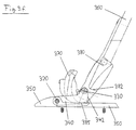
- FIGS. 3.a to 3.f show a second preferred embodiment of the invention shown, the one shown in Figures 1 and 2 and described above Embodiment is similar.
- the intermediate link 340 is made much shorter than the intermediate link 240 described above, and the transverse axis 330 is in Area below the toe as an integral part of the shoe rack 360 trained cam body 380 arranged.
- the transverse axis 330 is in Area below the toe as an integral part of the shoe rack 360 trained cam body 380 arranged.
- the transverse axis 330 in the area of the shoe tip results from the action of the curve body 380 for the first phase of the movement approximates a pivot point in the ball area and thus an ergonomic sequence of movements.
- a second stop is provided so that pivoting in the direction of lowering the heel over the joint position when lowered Shoe is made impossible. This prevents the double joint in the Departure position of the binding of an upward force of the toe, such as they e.g. can arise when skiing with reserve, yields undesirably.
- a stop can also be useful in the ascent position of the binding, e.g. when performing stair steps or hairpin bends on the ascent.
- a projection on the cam body 380 molded on in the binding position with the heel of the shoe lowered with its front 382 against a correspondingly shaped rear side 342 of the intermediate member 340 bumps.
- the intermediate member 340 is at the end with the first transverse axis 330 upwards raised, and its rear 342 abuts the correspondingly shaped front 382 on a projection formed on the curve body 380 and thereby forms a stop to limit the pivoting movement about the first transverse axis 330, thus panning in the direction of lowering the heel over the joint position with the boot lowered - or lifting the ski boot in the area of the Shoe toe - is made impossible.
- the heel When the heel is raised ( Figures 3.d to 3.e) it wanders the contact line 385 of the curve body 380 on the fastening part 350 continuously forward, with the intermediate member 340 in the area of its first Transverse axis 330 is first lowered and later raised again. All in all this embodiment of the invention also provides a round, ergonomic Sequence of movements.
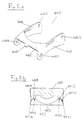
- FIGS. 4 and 5 show a third preferred embodiment of the invention, that of the first preferred embodiment shown in FIGS. 1 and 2 and the second preferred embodiment shown in FIGS. 3.a to 3.f. is similar.
- FIGS. 4 and 5 As a joint between the shoe carrier 460 of the shoe fastening means and the top of the ski 410 shows the embodiment of the invention shown in FIGS. 4 and 5 again a double joint-like device on: the carrier 460 with a front sole hold-down device 470 is pivotable about a first transverse axis 430 an intermediate link 440 which is pivotable about a second transverse axis 420 is hinged to a fastening part 450.
- the one-piece intermediate member 440 in the third preferred embodiment of the invention from a medium, plate-shaped Web part 445 and two plate-shaped lateral leg parts 444, 446. Die Plates of the two leg parts 444, 446 are approximately at right angles to the plate of the Bridge section 445 arranged.
- the leg portions 444, 446 are with holes 448.1 - 448.4 for the swivel axes 420 and 430.
- a cam 447 on the web portion 445 which is used to accommodate the following described compression spring 425 is formed.
- the one-piece fastening part 450 can be fastened to the ski with screws.
- the fastener 450 is behind the bearing for the second transverse axis 420, in the longitudinal direction of the ski viewed, elongated plate-shaped to the rear.
- On the side edges of the The top surfaces of this plate-shaped extension 453 are the counter surfaces 451.1 - 451.4 on which the convex curved surfaces mentioned below 481.1 - 481.4 of the curve body 480 are rolled off.
- a curved body 480 is formed on the carrier 460 in its foremost region is formed as an integral part of the carrier 460.
- On the side edges of the The underside of the curve body 480 is four which are convexly curved in the longitudinal direction of the ski Surfaces 481.1-481.4 are formed, which define a rolling / rolling curve.
- the curved surface of the curve body 480 and the corresponding counter surface on the upper side of the fastening part 450 not from a single, continuous one Area, but they are each in four partial areas 481.1 - 481.4 or 451.1 - 451.4 divided. This can best be seen in the cross section of FIG. 5.b.
- Two curved ones Subareas 481.1, 481.2 of the curve body 480 are arranged such that they form a step running along one side edge of the curve body 480.
- a corresponding step is formed by the two counter surfaces 451.1, 451.2 corresponding longitudinal edge on the top of the plate-shaped extension 453 of the fixing part 450.
- the two stages work when the cam body is rolled off 480 together on the plate-shaped extension 453 such that the Curve body 480 is guided on one side in the longitudinal direction.
- two further curved surfaces 481.3, 481.4 are arranged such that it runs along the other side edge of the curve body 480 form another level.
- the other two counter surfaces make the same 451.3, 451.4 a corresponding step on the corresponding other longitudinal edge on the Formed top of the plate-shaped extension 453 of the fastening part 450, the two stages in turn rolling the cam body 480 on the plate-shaped extension 453 cooperate such that the cam body 480 is guided on one side in the longitudinal direction.
- the plate-shaped extension serves 453 thus as a guide rail for longitudinal guidance of the curve body 480 if the latter on the top of the plate-shaped extension 453 of the fastening part 450 is passed on.
- the middle part of the top of the plate-shaped extension 453 with a groove-shaped depression 455 which is arranged in the longitudinal direction of the ski.
- the longitudinal groove 455 creates space for the foremost part of the shoe wearer 460 and the lowest part of the sole hold-down device 470, if this is created Parts in the course of the joint movement between the shoe carrier 460 and the Shoe and the ski are moved down when lifting the shoe heel.
- the gutter is also used to transport snow away when walking with the Ski binding in the joint area and the area between the shoe carrier 460 as well as the ski top 410 penetrates.
- the groove 455 is designed such that any snow penetrated into the binding area due to the movement of the joints the appropriately trained front part of the shoe carrier 460 and / or the Sole holding-down device 470 is conveyed backwards through the groove 455.
- Figure 4.a the binding is shown in the position with the heel of the shoe lowered.
- the Figure 4.b shows the binding in a position in which the shoe carrier 460 opposite top 410 forms an angle of approximately 60 degrees.
- the shoe carrier 460 was over 90 degrees the horizontal position.
- the invention is preferred in the third described in Figures 4 and 5 Embodiment of the invention to limit the pivoting movement around the first transverse axis 430 in the rearward direction in turn provides a stop which corresponds to the second stop described above.
- a protrusion with its front 482 against a correspondingly shaped rear side 442 of the intermediate member 440 bumps.
- the invention lacks the first stop in those described above Embodiments of the invention corresponding stop, which in a certain Position the continuation of the pivoting movement about the transverse axis 430 would block.
- the sole hold-down device 470 is designed in such a way that that its front outside defines a convex curved contour line.
- the sole hold-down device 470 quasi as a continuation and curve body and controls the joint movement by is rolled on the fastening part 450.
- two springs 425, 435 on the Binding arranged.
- the tension spring 435 (also called a spring) is on the one hand on the intermediate member 440 - concrete on the inside of the leg portion 446 of the intermediate member 440 - and on the other hand attached to a longitudinal outside of the curve body 480.
- the tension spring 435 thus acts when lifting the heel of the pivoting movement about the first transverse axis 430 counter and prevents that if the skier together with the ski boot of the ski attached to the binding lifts the rear end of the ski down hangs.
- the compression spring 425 is between the front part of the fastening part 450 and arranged the intermediate member 440 and acts the pivoting movement about the second Transverse axis 420 counter that the intermediate member 440 about the second pivot axis 420 downwards, in the direction of the ski top 410.
- the Compression spring 425 is link-side from the front side of the link web section 445 molded cams 447 added.
- the two springs 425, 435 are designed and arranged such that the Compression spring 425 a greater torque with respect to the second pivot axis 420 is exerted as by the tension spring 435 with respect to the first pivot axis 430. This ensures that during the whole joint movement, the essentially executed between the shoe carrier 460 and the mounting plate 450 the curve body 480, which is designed as an integral part of the shoe carrier 460, always is rolled on the plate-shaped extension 453 of the fastening part 450 and the joint movement is thus controlled by the cam body.
- FIGS. 4 and 5 provides an even rounder and more ergonomic movement than the wider one Embodiments of the invention described above.
- FIG. 6 has the ski binding instead of the double joint mentioned above with two transverse axes just a rotary-thrust joint 600, 605, 630.
- the curved body 680 which as an integral Part of a carrier 660 receiving the ski boot (not shown) with a front hold-down device 670 is formed, is pivotable about a transverse axis 630 hinged to a fastening part 600.
- the fastening part 600 is open the ski top 610 attached to the ski.
- the transverse axis 630 is along a straight, in essentially vertically arranged guide slot device 605.
- FIG. 7 In the fifth preferred embodiment of the invention shown in FIG. 7 becomes sliding through a surface corresponding to the convexly curved surface 781 Avoided joint 700, 705, 730.
- a curvilinear guide slot device 705 for guiding the transverse axis 730.
- the curvature of the guide slot device 705 is such on the curvature of the convexly curved surface 781 of the curved body 780 that when rolling the convex surface 781 no sliding occurs on the counter surface 751 because the transverse axis 730 through the Guide slot device 705 is guided downwards and forwards at the same time.
- the curve body is not on the shoe fasteners, but on the top of the ski arranged, the convex curved surface on the top of the Curved body lies. The rolling process then takes place between this convexly curved Surface and a counter surface instead, either on the bottom of the Shoe fastener or ski boot.
- the curve body not only is the curve body, but also the counter surface is curved in the longitudinal direction of the ski.
- the passing curve then results by rolling one curved surface onto another curved surface Surface.
- the shoe fastening means e.g. include bushings embedded in the sole of the ski boot which correspond to which Can engage pins on the intermediate link.
- a rolling or sliding device is provided be. So, for example, a roller carriage or below the curve body a sliding carriage can be provided, the top of which forms the counter surface on which the convex surface of the curve body is rolled without sliding, whereby the roller carriage moves at the same time.
- a roller carriage you can also use a series be provided by rollers on the counter surface on which the cam body is rolled becomes.
- the rollers can also be curved along the convex Curve line of the curve body can be arranged and on the non-displaceable counter surface be passed on.
- the cam body is by means of a sliding joint attached to the shoe fasteners or the top of the ski.
- a sliding joint attached to the shoe fasteners or the top of the ski.
- the counter surface is the curve body when rolling between the curve body and the counter surface slidable along the sliding joint.
- the cam body can be used to avoid sliding between the convexly curved surface of the curve body and the counter surface by one additional transverse axis pivotable on the shoe fastening means or on the top of the ski be attached.
- the invention provides a touring binding that is ergonomic, the anatomy of the human body appropriate movement sequence when walking and especially when climbing Skis allowed. Above the ankle there is for the skier himself Using a ski boot with a stiff sole means a similar sequence of movements like running or walking with a soft-soled running shoe.
Landscapes
- Footwear And Its Accessory, Manufacturing Method And Apparatuses (AREA)
Abstract
Description
- Fig. 1.a
- schematische Seiten-Teilansicht einer ersten bevorzugten Ausführungsform der erfindungsgemässen Skibindung, in einer Position mitabgesenkter Schuhferse;
- Fig. 1.b
- schematische Seiten-Teilansicht der Ausführungsform aus Figur 1.a in einer ersten Gelenk-Position mit angehobener Schuhferse;
- Fig. 1.c
- schematische Seiten-Teilansicht der Ausführungsform aus Figur 1.a in einer zweiten Gelenk-Position mit angehobener Schuhferse;
- Fig. 2
- perspektivische Detailansicht des Zwischenglieds gemäss der in den Figuren 1.a bis 1.c dargestellten Ausführungsform der Erfindung;
- Fig. 3.a
- Seiten-Teilansicht einer zweiten bevorzugten Ausführungsform der erfindungsgemässen Skibindung;
- Fig. 3.b
- Seiten-Detailansicht des Zwischenglieds gemäss der in Figur 3.a dargestellten Ausführungsform der Erfindung;
- Fig. 3.c
- schematische Seiten-Teilansicht der Ausführungsform aus Figur 3.a in einer ersten Gelenk-Position;
- Fig. 3.d
- schematische Seiten-Teilansicht der Ausführungsform aus Figur 3.a in einer zweiten Gelenk-Position;
- Fig. 3.e
- schematische Seiten-Teilansicht der Ausführungsform aus Figur 3.a in einer dritten Gelenk-Position;
- Fig. 3.f
- schematische Seiten-Teilansicht der Ausführungsform aus Figur 3.a in einer vierten Gelenk-Position;
- Fig. 4.a
- schematische Seiten-Teilansicht einer dritten bevorzugten Ausführungsform der erfindungsgemässen Skibindung, in einer Position mitabgesenkter Schuhferse;
- Fig. 4.b
- schematische Seiten-Teilansicht der Ausführungsform aus Figur 4.a in einer ersten Gelenk-Position mit angehobener Schuhferse;
- Fig. 4.c
- schematische Seiten-Teilansicht der Ausführungsform aus Figur 4.a in einer zweiten Gelenk-Position mit angehobener Schuhferse;
- Fig. 5.a
- perspektivische Detailansicht des Zwischenglieds gemäss der in den Figuren 4.a bis 4.c dargestellten Ausführungsform der Erfindung;
- Fig. 5.b
- Querschnitt entlang der Linie A-A in der Figur 4.a;
- Fig. 6
- schematische Seiten-Teilansicht einer vierten Ausführungsform der erfindungsgemässen Skibindung;
- Fig. 7
- schematische Seiten-Teilansicht einer fünften Ausführungsform der erfindungsgemässen Skibindung.
Claims (12)
- Skibindung mit Schuhbefestigungsmitteln (260, 270; 360, 370; 460, 470; 660, 670; 760, 770), die gelenkig um mindestens eine Querachse (230; 630; 730) verschwenkbar am Ski befestigt sind, gekennzeichnet durch einen die Gelenkbewegung zwischen den Schuhbefestigungsmitteln (260, 270; 360, 370; 460, 470; 660, 670; 760, 770) und dem Ski steuernden Kurvenkörper (280; 380; 480; 680; 780) mit einer mindestens in einem Bereich in Skilängsrichtung konvex gekrümmten Oberfläche (281; 381; 481; 681; 781).
- Skibindung nach Anspruch 1, dadurch gekennzeichnet, dass bei abgesenktem Schuh der Kurvenkörper (280; 380; 480; 680; 780) in einem Bereich zwischen Schuh und Ski, in Skilängsrichtung betrachtet vor der Schuhmitte angeordnet ist.
- Skibindung nach Anspruch 1 oder 2, dadurch gekennzeichnet, dass der Kurvenkörper (280; 380; 480; 680; 780) derart ausgebildet und angeordnet ist, dass mindestens in einer Phase der Gelenkbewegung der Kurvenkörper (280; 380; 480; 680; 780) so abgewälzt wird, dass der Abstand zwischen der Schuhferse und der Auflagelinie (285; 385; 485; 685; 785) des Kurvenkörpers (280; 380; 480; 680; 780) bei zunehmender Anhebung der Schuhferse zunimmt.
- Skibindung nach einem der Ansprüche 1 bis 3, dadurch gekennzeichnet, dass der Kurvenkörper (480) zur Längsführung des Kurvenkörpers (480) während der Gelenkbewegung mit mindestens zwei stufenförmig angeordneten Oberflächen (481.1, 481.2, 481.3, 481.4) versehen ist.
- Skibindung nach einem der Ansprüche 1 bis 4, dadurch gekennzeichnet, dass der Kurvenkörper (280; 380; 480; 680; 780) an den Schuhbefestigungsmitteln (260, 270; 360, 370; 460, 470; 660, 670; 760, 770) und/oder den am Schuh angebrachten Bindungsteilen derart angeordnet ist, dass bei abgesenktem Schuh die konvex gekrümmte Oberfläche (281; 381; 481; 681; 781) auf der Unterseite des Kurvenkörpers (280; 380; 480; 680; 780) liegt.
- Skibindung nach Anspruch 5, dadurch gekennzeichnet, dass auf dem Ski und/oder auf den am Ski angebrachten Bindungsteilen eine Rippe (290) quer zur Skilängsrichtung derart unter dem Kurvenkörper (280) angeordnet ist, dass mindestens in einer Phase der Gelenkbewegung der Kurvenkörper (280) auf der Rippe (290) abgewälzt wird, wobei der Abstand zwischen der Schuhferse und der Auflagelinie (285) des Kurvenkörpers (280) bei zunehmender Anhebung der Schuhferse im wesentlichen konstant bleibt.
- Skibindung nach einem der Ansprüche 1 bis 6, dadurch gekennzeichnet, dass der Kurvenkörper (280; 380; 480; 680; 780) als Teil derSchuhbefestigungsmittel (260, 270; 360, 370; 460, 470; 660, 670; 760, 770) ausgeführt ist.
- Skibindung nach Anspruch 7, dadurch gekennzeichnet, dass die Schuhbefestigungsmittel (260, 270; 360, 370; 460, 470; 660, 670; 760, 770) einen Träger (260; 360; 460; 660; 760) umfassen, auf dem der Skischuh befestigbar ist, wobei der Kurvenkörper (280; 380; 480; 680; 780) als Vorderpartie dieses Trägers (260; 360; 460; 660; 760) ausgebildet ist.
- Skibindung nach einem der Ansprüche 1 bis 8, dadurch gekennzeichnet, dass die Schuhbefestigungsmittel (260, 270; 360, 370; 460, 470) um eine erste Querachse (230; 330; 430) verschwenkbar an einem Zwischenglied (240; 340; 440) angelenkt sind, welches um eine zweite Querachse (220; 320; 420) verschwenkbar am Ski angelenkt ist.
- Skibindung nach Anspruch 9, gekennzeichnet durch eine zwischen dem Zwischenglied (440) und den Schuhbefestigungsmitteln (460) wirkende Feder (435), die derart ausgebildet und angeordnet ist, dass sie einer Schwenkbewegung der Schuhbefestiungsmittel (460) in Richtung einer zunehmender Anhebung der Schuhferse um die erste Querachse 430 herum entgegenwirkt.
- Skibindung nach Anspruch 9 oder 10, gekennzeichnet durch eine zwischen dem Zwischenglied (440) und dem Ski wirkende Feder (425), die derart ausgebildet und angeordnet ist, dass sie einer Schwenkbewegung des Zwischengliedes (460) in Richtung eines zunehmenden Winkels zwischen dem Ski und dem Zwischenglied (440) um die zweite Querachse (420) herum entgegenwirkt.
- Skibindung nach Anspruch 9 und 10, dadurch gekennzeichnet, dass die beiden Federn (425, 435) derart ausgebildet und angeordnet sind, dass durch die zwischen dem Zwischenglied (440) und dem Ski wirkende Feder (425) bezüglich der zweiten Querachse (420) ein grösseres Drehmoment ausgeübt wird als durch die zwischen dem Zwischenglied (440) und den Schuhbefestigungsmitteln (460) wirkende Feder (435) bezüglich der ersten Querachse (430).
Priority Applications (2)
| Application Number | Priority Date | Filing Date | Title |
|---|---|---|---|
| DE29824950U DE29824950U1 (de) | 1997-07-07 | 1998-07-07 | Skibindung |
| EP98810645A EP0890379B2 (de) | 1997-07-07 | 1998-07-07 | Skibindung |
Applications Claiming Priority (5)
| Application Number | Priority Date | Filing Date | Title |
|---|---|---|---|
| EP97810448A EP0890377A1 (de) | 1997-07-07 | 1997-07-07 | Skibindung |
| EP97810449 | 1997-07-07 | ||
| EP97810449A EP0890378A1 (de) | 1997-07-07 | 1997-07-07 | Skibindung |
| EP97810448 | 1997-07-07 | ||
| EP98810645A EP0890379B2 (de) | 1997-07-07 | 1998-07-07 | Skibindung |
Publications (3)
| Publication Number | Publication Date |
|---|---|
| EP0890379A1 true EP0890379A1 (de) | 1999-01-13 |
| EP0890379B1 EP0890379B1 (de) | 2003-09-17 |
| EP0890379B2 EP0890379B2 (de) | 2007-03-28 |
Family
ID=27238765
Family Applications (1)
| Application Number | Title | Priority Date | Filing Date |
|---|---|---|---|
| EP98810645A Expired - Lifetime EP0890379B2 (de) | 1997-07-07 | 1998-07-07 | Skibindung |
Country Status (2)
| Country | Link |
|---|---|
| EP (1) | EP0890379B2 (de) |
| DE (1) | DE29824950U1 (de) |
Cited By (17)
| Publication number | Priority date | Publication date | Assignee | Title |
|---|---|---|---|---|
| EP1034819A3 (de) * | 1999-03-01 | 2001-08-08 | Martin Dipl. Ing. Breuer-Bono | Tourenschibindung mit Doppelgelenksmechanik |
| US6499761B1 (en) | 1998-09-02 | 2002-12-31 | Salomon S.A. | Device for fixing a shoe to a sports article |
| FR2833179A1 (fr) | 2001-12-11 | 2003-06-13 | Salomon Sa | Dispositif de fixation sans soulevement d'une chaussure a un article de sport |
| FR2833178A1 (fr) | 2001-12-11 | 2003-06-13 | Salomon Sa | Dispositif de fixation d'une chaussure a un article de sport comportant des moyens de rappel perfectionnes |
| EP1321173A1 (de) | 2001-12-21 | 2003-06-25 | Fritschi AG - Swiss Bindings | Skibindung |
| FR2836393A1 (fr) | 2002-02-28 | 2003-08-29 | Salomon Sa | Dispositif de fixation a ressort de compression |
| EP1388356A1 (de) | 2002-08-08 | 2004-02-11 | Salomon S.A. | Bindungsanlage mit Frontentkupplung |
| FR2843311A1 (fr) | 2002-08-08 | 2004-02-13 | Salomon Sa | Dispositif de fixation a accrochage integre |
| FR2850031A1 (fr) | 2003-01-21 | 2004-07-23 | Salomon Sa | Fixation a energie deportee |
| WO2004089481A2 (fr) | 2003-04-03 | 2004-10-21 | Salom0N S.A. | Fixation avec un organe de liaison en deux parties |
| EP1559456A1 (de) | 2004-01-30 | 2005-08-03 | Salomon S.A. | skibindung mit integrierter auslösung |
| EP1616604A1 (de) | 2004-07-13 | 2006-01-18 | Salomon S.A. | Bindungsanlage für einen Schuh an einem Sportgerät mit getrennten elastischen Rückstellmitteln |
| US7111865B2 (en) | 2003-06-18 | 2006-09-26 | Salomon S.A. | Binding device having a pivotable arm |
| EP1839711A1 (de) * | 1998-11-12 | 2007-10-03 | ATOMIC Austria GmbH | Schwenkbare Verbindungseinrichtung zwischen Sportgerät und Schuh |
| EP1854513A1 (de) * | 2006-05-12 | 2007-11-14 | Fritschi AG - Swiss Bindings | Skibindung |
| WO2009077410A1 (de) * | 2007-12-19 | 2009-06-25 | Krueger, Clemens | Verbindungselement zwischen einem schuh und einem fortbewegungsmittel |
| US11865433B2 (en) * | 2021-10-28 | 2024-01-09 | Fritschiag—Swiss Bindings | Skibinding, in particular touring skibinding |
Citations (4)
| Publication number | Priority date | Publication date | Assignee | Title |
|---|---|---|---|---|
| AT343522B (de) | 1975-12-24 | 1978-06-12 | Hausleithner Andreas | Kabellose sicherheitsschibindung |
| CH659397A5 (en) | 1982-01-21 | 1987-01-30 | I & R Gmbh | Ski binding with a walking attachment |
| US4854605A (en) * | 1988-06-29 | 1989-08-08 | Emerson Kenneth D | Ski binding for mountain skiing |
| WO1996023559A1 (de) | 1995-02-01 | 1996-08-08 | Fritschi Ag Apparatebau | Schibindung |
Family Cites Families (1)
| Publication number | Priority date | Publication date | Assignee | Title |
|---|---|---|---|---|
| US4410199A (en) † | 1980-12-16 | 1983-10-18 | Eisenberg Joel Howard | Cross-country ski boot binding |
-
1998
- 1998-07-07 EP EP98810645A patent/EP0890379B2/de not_active Expired - Lifetime
- 1998-07-07 DE DE29824950U patent/DE29824950U1/de not_active Expired - Lifetime
Patent Citations (4)
| Publication number | Priority date | Publication date | Assignee | Title |
|---|---|---|---|---|
| AT343522B (de) | 1975-12-24 | 1978-06-12 | Hausleithner Andreas | Kabellose sicherheitsschibindung |
| CH659397A5 (en) | 1982-01-21 | 1987-01-30 | I & R Gmbh | Ski binding with a walking attachment |
| US4854605A (en) * | 1988-06-29 | 1989-08-08 | Emerson Kenneth D | Ski binding for mountain skiing |
| WO1996023559A1 (de) | 1995-02-01 | 1996-08-08 | Fritschi Ag Apparatebau | Schibindung |
Cited By (21)
| Publication number | Priority date | Publication date | Assignee | Title |
|---|---|---|---|---|
| US6499761B1 (en) | 1998-09-02 | 2002-12-31 | Salomon S.A. | Device for fixing a shoe to a sports article |
| EP1839711A1 (de) * | 1998-11-12 | 2007-10-03 | ATOMIC Austria GmbH | Schwenkbare Verbindungseinrichtung zwischen Sportgerät und Schuh |
| EP1034819A3 (de) * | 1999-03-01 | 2001-08-08 | Martin Dipl. Ing. Breuer-Bono | Tourenschibindung mit Doppelgelenksmechanik |
| FR2833179A1 (fr) | 2001-12-11 | 2003-06-13 | Salomon Sa | Dispositif de fixation sans soulevement d'une chaussure a un article de sport |
| FR2833178A1 (fr) | 2001-12-11 | 2003-06-13 | Salomon Sa | Dispositif de fixation d'une chaussure a un article de sport comportant des moyens de rappel perfectionnes |
| EP1321173A1 (de) | 2001-12-21 | 2003-06-25 | Fritschi AG - Swiss Bindings | Skibindung |
| WO2003072208A1 (fr) | 2002-02-28 | 2003-09-04 | Salomom S.A. | Dispositif de fixation a ressort de compression |
| FR2836393A1 (fr) | 2002-02-28 | 2003-08-29 | Salomon Sa | Dispositif de fixation a ressort de compression |
| EP1388356A1 (de) | 2002-08-08 | 2004-02-11 | Salomon S.A. | Bindungsanlage mit Frontentkupplung |
| FR2843311A1 (fr) | 2002-08-08 | 2004-02-13 | Salomon Sa | Dispositif de fixation a accrochage integre |
| FR2850031A1 (fr) | 2003-01-21 | 2004-07-23 | Salomon Sa | Fixation a energie deportee |
| US7320474B2 (en) | 2003-01-21 | 2008-01-22 | Salomon S.A. | Device for binding a boot to a sports article |
| US6964428B2 (en) | 2003-01-21 | 2005-11-15 | Salomon S.A. | Device for binding a boot to a sports article |
| WO2004089481A2 (fr) | 2003-04-03 | 2004-10-21 | Salom0N S.A. | Fixation avec un organe de liaison en deux parties |
| US7111865B2 (en) | 2003-06-18 | 2006-09-26 | Salomon S.A. | Binding device having a pivotable arm |
| US7264264B2 (en) | 2003-06-18 | 2007-09-04 | Salomon S.A. | Binding device having a pivotable arm |
| EP1559456A1 (de) | 2004-01-30 | 2005-08-03 | Salomon S.A. | skibindung mit integrierter auslösung |
| EP1616604A1 (de) | 2004-07-13 | 2006-01-18 | Salomon S.A. | Bindungsanlage für einen Schuh an einem Sportgerät mit getrennten elastischen Rückstellmitteln |
| EP1854513A1 (de) * | 2006-05-12 | 2007-11-14 | Fritschi AG - Swiss Bindings | Skibindung |
| WO2009077410A1 (de) * | 2007-12-19 | 2009-06-25 | Krueger, Clemens | Verbindungselement zwischen einem schuh und einem fortbewegungsmittel |
| US11865433B2 (en) * | 2021-10-28 | 2024-01-09 | Fritschiag—Swiss Bindings | Skibinding, in particular touring skibinding |
Also Published As
| Publication number | Publication date |
|---|---|
| EP0890379B1 (de) | 2003-09-17 |
| DE29824950U1 (de) | 2003-09-11 |
| EP0890379B2 (de) | 2007-03-28 |
Similar Documents
| Publication | Publication Date | Title |
|---|---|---|
| EP0890379B1 (de) | Skibindung | |
| EP0551899B1 (de) | Langlauf- oder Tourenskibindung für Langlaufskischuhe | |
| EP1292369B1 (de) | Anordnung aus einer skibindung und einem skischuh | |
| DE69710989T2 (de) | Sportschuh mit beweglichem Oberteil | |
| DE69620534T2 (de) | Schuh-Bindungseinheit | |
| DE4343485C1 (de) | Anordnung einer Langlaufskibindung | |
| DE3708838A1 (de) | Anordnung zum festhalten eines ski-schuhs auf einem langlauf- oder touren-ski | |
| EP0167765B1 (de) | Skischuh | |
| DE69925214T2 (de) | Vorrichtung zum verbinden eines schuhs mit einem sportartikel | |
| EP0612546A2 (de) | Snowboardbindung | |
| DE3707116C2 (de) | Skibindung für einen Langlauf- oder Touren-Ski | |
| EP1839711B1 (de) | Schwenkbare Verbindungseinrichtung zwischen Sportgerät und Schuh | |
| EP0581802B1 (de) | Sportschuh | |
| DE3633098C2 (de) | ||
| DE69818196T2 (de) | Langlaufskischuh | |
| EP2022543B1 (de) | Verbindungseinheit | |
| EP1022037A1 (de) | Telemark-Skibindung | |
| DE69407060T2 (de) | Langlaufskischuh, -bindung und -schuheinheit | |
| DE69613548T2 (de) | Gleitbrett mit Versteifungsvorrichtung | |
| DE4036962C2 (de) | Skischuh | |
| DE69601834T2 (de) | Übungsmittel zum Erlernen des Skilanglaufs nach der Schlittschuhlaufschritttechnik | |
| EP4173682B1 (de) | Skibindung, insbesondere tourenskibindung | |
| EP1321173B1 (de) | Skibindung | |
| EP0672364A2 (de) | Skischuh | |
| EP0214201A1 (de) | Einrichtung zur festlegung eines langlaufschischuhs auf einem langlaufschi. |
Legal Events
| Date | Code | Title | Description |
|---|---|---|---|
| PUAI | Public reference made under article 153(3) epc to a published international application that has entered the european phase |
Free format text: ORIGINAL CODE: 0009012 |
|
| AK | Designated contracting states |
Kind code of ref document: A1 Designated state(s): AT CH DE FR IT LI |
|
| AX | Request for extension of the european patent |
Free format text: AL;LT;LV;MK;RO;SI |
|
| 17P | Request for examination filed |
Effective date: 19990417 |
|
| AKX | Designation fees paid |
Free format text: AT CH DE FR IT LI |
|
| GRAH | Despatch of communication of intention to grant a patent |
Free format text: ORIGINAL CODE: EPIDOS IGRA |
|
| GRAH | Despatch of communication of intention to grant a patent |
Free format text: ORIGINAL CODE: EPIDOS IGRA |
|
| GRAA | (expected) grant |
Free format text: ORIGINAL CODE: 0009210 |
|
| AK | Designated contracting states |
Kind code of ref document: B1 Designated state(s): AT CH DE FR IT LI |
|
| REG | Reference to a national code |
Ref country code: CH Ref legal event code: EP |
|
| RAP2 | Party data changed (patent owner data changed or rights of a patent transferred) |
Owner name: FRITSCHI AG - SWISS BINDINGS |
|
| REG | Reference to a national code |
Ref country code: CH Ref legal event code: NV Representative=s name: KELLER & PARTNER PATENTANWAELTE AG |
|
| REF | Corresponds to: |
Ref document number: 59809617 Country of ref document: DE Date of ref document: 20031023 Kind code of ref document: P |
|
| ET | Fr: translation filed | ||
| PLBQ | Unpublished change to opponent data |
Free format text: ORIGINAL CODE: EPIDOS OPPO |
|
| PLBI | Opposition filed |
Free format text: ORIGINAL CODE: 0009260 |
|
| PLAX | Notice of opposition and request to file observation + time limit sent |
Free format text: ORIGINAL CODE: EPIDOSNOBS2 |
|
| 26 | Opposition filed |
Opponent name: NAXO AG Effective date: 20040616 |
|
| PLAX | Notice of opposition and request to file observation + time limit sent |
Free format text: ORIGINAL CODE: EPIDOSNOBS2 |
|
| PLBB | Reply of patent proprietor to notice(s) of opposition received |
Free format text: ORIGINAL CODE: EPIDOSNOBS3 |
|
| PUAH | Patent maintained in amended form |
Free format text: ORIGINAL CODE: 0009272 |
|
| STAA | Information on the status of an ep patent application or granted ep patent |
Free format text: STATUS: PATENT MAINTAINED AS AMENDED |
|
| 27A | Patent maintained in amended form |
Effective date: 20070328 |
|
| AK | Designated contracting states |
Kind code of ref document: B2 Designated state(s): AT CH DE FR IT LI |
|
| REG | Reference to a national code |
Ref country code: CH Ref legal event code: AEN Free format text: AUFRECHTERHALTUNG DES PATENTES IN GEAENDERTER FORM |
|
| ET3 | Fr: translation filed ** decision concerning opposition | ||
| PG25 | Lapsed in a contracting state [announced via postgrant information from national office to epo] |
Ref country code: IT Free format text: LAPSE BECAUSE OF NON-PAYMENT OF DUE FEES Effective date: 20070707 |
|
| PGFP | Annual fee paid to national office [announced via postgrant information from national office to epo] |
Ref country code: FR Payment date: 20090629 Year of fee payment: 12 |
|
| REG | Reference to a national code |
Ref country code: FR Ref legal event code: ST Effective date: 20110331 |
|
| PG25 | Lapsed in a contracting state [announced via postgrant information from national office to epo] |
Ref country code: FR Free format text: LAPSE BECAUSE OF NON-PAYMENT OF DUE FEES Effective date: 20100802 |
|
| PGFP | Annual fee paid to national office [announced via postgrant information from national office to epo] |
Ref country code: IT Payment date: 20090730 Year of fee payment: 12 |
|
| PGRI | Patent reinstated in contracting state [announced from national office to epo] |
Ref country code: IT Effective date: 20110616 |
|
| PGFP | Annual fee paid to national office [announced via postgrant information from national office to epo] |
Ref country code: AT Payment date: 20130726 Year of fee payment: 16 Ref country code: DE Payment date: 20130706 Year of fee payment: 16 |
|
| PGRI | Patent reinstated in contracting state [announced from national office to epo] |
Ref country code: IT Effective date: 20110616 |
|
| PGFP | Annual fee paid to national office [announced via postgrant information from national office to epo] |
Ref country code: CH Payment date: 20140619 Year of fee payment: 17 |
|
| REG | Reference to a national code |
Ref country code: DE Ref legal event code: R119 Ref document number: 59809617 Country of ref document: DE |
|
| REG | Reference to a national code |
Ref country code: AT Ref legal event code: MM01 Ref document number: 249863 Country of ref document: AT Kind code of ref document: T Effective date: 20140707 |
|
| REG | Reference to a national code |
Ref country code: CH Ref legal event code: PCAR Free format text: NEW ADDRESS: EIGERSTRASSE 2 POSTFACH, 3000 BERN 14 (CH) |
|
| PG25 | Lapsed in a contracting state [announced via postgrant information from national office to epo] |
Ref country code: DE Free format text: LAPSE BECAUSE OF NON-PAYMENT OF DUE FEES Effective date: 20150203 |
|
| REG | Reference to a national code |
Ref country code: DE Ref legal event code: R119 Ref document number: 59809617 Country of ref document: DE Effective date: 20150203 |
|
| PG25 | Lapsed in a contracting state [announced via postgrant information from national office to epo] |
Ref country code: AT Free format text: LAPSE BECAUSE OF NON-PAYMENT OF DUE FEES Effective date: 20140707 |
|
| REG | Reference to a national code |
Ref country code: CH Ref legal event code: PL |
|
| PG25 | Lapsed in a contracting state [announced via postgrant information from national office to epo] |
Ref country code: LI Free format text: LAPSE BECAUSE OF NON-PAYMENT OF DUE FEES Effective date: 20150731 Ref country code: CH Free format text: LAPSE BECAUSE OF NON-PAYMENT OF DUE FEES Effective date: 20150731 |