EP0886620B1 - Device for continuously winding up longitudinally cut paper webs with rolls changed automatically at the machine speed - Google Patents
Device for continuously winding up longitudinally cut paper webs with rolls changed automatically at the machine speed Download PDFInfo
- Publication number
- EP0886620B1 EP0886620B1 EP97907097A EP97907097A EP0886620B1 EP 0886620 B1 EP0886620 B1 EP 0886620B1 EP 97907097 A EP97907097 A EP 97907097A EP 97907097 A EP97907097 A EP 97907097A EP 0886620 B1 EP0886620 B1 EP 0886620B1
- Authority
- EP
- European Patent Office
- Prior art keywords
- winding
- discs
- pairs
- paper webs
- web
- Prior art date
- Legal status (The legal status is an assumption and is not a legal conclusion. Google has not performed a legal analysis and makes no representation as to the accuracy of the status listed.)
- Expired - Lifetime
Links
Images
Classifications
-
- B—PERFORMING OPERATIONS; TRANSPORTING
- B65—CONVEYING; PACKING; STORING; HANDLING THIN OR FILAMENTARY MATERIAL
- B65H—HANDLING THIN OR FILAMENTARY MATERIAL, e.g. SHEETS, WEBS, CABLES
- B65H18/00—Winding webs
- B65H18/02—Supporting web roll
- B65H18/021—Multiple web roll supports
- B65H18/0212—Turrets
-
- B—PERFORMING OPERATIONS; TRANSPORTING
- B65—CONVEYING; PACKING; STORING; HANDLING THIN OR FILAMENTARY MATERIAL
- B65H—HANDLING THIN OR FILAMENTARY MATERIAL, e.g. SHEETS, WEBS, CABLES
- B65H19/00—Changing the web roll
- B65H19/22—Changing the web roll in winding mechanisms or in connection with winding operations
- B65H19/2284—Simultaneous winding at several stations, e.g. slitter-rewinders
-
- B—PERFORMING OPERATIONS; TRANSPORTING
- B65—CONVEYING; PACKING; STORING; HANDLING THIN OR FILAMENTARY MATERIAL
- B65H—HANDLING THIN OR FILAMENTARY MATERIAL, e.g. SHEETS, WEBS, CABLES
- B65H2301/00—Handling processes for sheets or webs
- B65H2301/40—Type of handling process
- B65H2301/41—Winding, unwinding
- B65H2301/414—Winding
- B65H2301/4148—Winding slitting
-
- B—PERFORMING OPERATIONS; TRANSPORTING
- B65—CONVEYING; PACKING; STORING; HANDLING THIN OR FILAMENTARY MATERIAL
- B65H—HANDLING THIN OR FILAMENTARY MATERIAL, e.g. SHEETS, WEBS, CABLES
- B65H2408/00—Specific machines
- B65H2408/20—Specific machines for handling web(s)
- B65H2408/23—Winding machines
- B65H2408/231—Turret winders
- B65H2408/2315—Turret winders specified by number of arms
- B65H2408/23155—Turret winders specified by number of arms with three arms
Definitions
- the invention relates to a device and a method for continuous winding of slit paper webs with automatic roll change Machine speed.
- Such a device is known from DE-B-1 474 243.
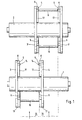
- FIG. 1 includes two in the transport direction Paper web 15 support rollers 1, 2 arranged one behind the other in the usual Aligned in a machine frame and rotatably mounted are arranged. Details of the storage and drives of the backup rolls are not shown to clarify the features belonging to the invention to emerge.
- a pair of disks 3, 4 belongs to each support roller 1, 2 or 3 ', 4', which is concentric with the support rollers 1, 2 and independent of this is rotatably mounted and its axial distance to the width of the paper webs 15 to be wound is adjustable.
- the exemplary embodiment is also simplified insofar as the overall system is only designed for two paper webs 15.
- Support rollers 1, 2 run longer or two can be used for each support roller 1, 2 or more pairs of discs 3, 4, 3 ', 4' if the original Paper web is wider than shown or in more than two paper webs to be separated.
- the disc pairs are transverse to Paper web staggered in such a way that the winding devices for the first, third, fifth, etc. paper web with the one support roller 1 work together and the rewinder for the second, fourth, sixth etc. paper web with the other backup roller 2.
- Embodiment can also be modified in such a way that more than two back-up rollers are provided and that the paper webs a first, a second and be assigned to a third backup roller.
- 3 ', 4' each arranged two offset by 180 ° to each other Winding devices 5, 6 are provided. They are in left and one each right guide 17 mounted so that it is possible to adjust it radially, for which known pneumatic, hydraulic or electric motor drives can be used.
- the diameter of the disk pairs 3, 4, 3 ', 4' chosen so that the largest possible diameter of a wound Paper web 16 always remains within the outer circumference 11 so that the Disc pairs 3, 4, 4 ', 4' on the necessary for their storage Machine frame can be swung past. Only in the Removal position, the wound paper webs 16 can continue radially be adjustable to the outside.
- the winding device 5 is attached Cardboard sleeve 9 shown, while the mandrels 14 in the lower part Winding device 5 can be seen.
- the bottom one Winding devices 6 carry a completely wound paper web 16. Dashed lines indicate the edges of the paper webs 15, which are below the device according to the invention are supplied.
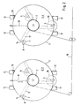
- FIG. 2 shows an embodiment of the invention with two support rollers 1 and 2 and two pairs of disks 3, 4, 3 ', 4' are shown, with the difference 1, three winding devices 5, 6, 7 with core drives 8 are provided. Accordingly, this device has three different ones Working positions, but otherwise does not differ from the example 1.
- the machine frame 12 with the drive 13 for the is also indicated Disc pairs 3, 4, 3 ', 4', the machine frame 12 also for storage the back-up rolls 1 and 2 are used and comprise devices not shown, by means of which the distance between the disks 3, 4 and 3 ', 4' to each other on the desired width of the paper webs 15 to be wound is adjustable. Details of the storage and adjustment devices are not shown.
- the device 10 is radially between the Disc pairs 3, 4, 3 ', 4' retractable and extendable. It works in a known manner with a compressed air pulse that cuts through the paper web and the new one Blows the beginning of the web against the empty cardboard sleeve 9, which suitably with an adhesive is layered so that the winding process without interference can run.
- a fully wound paper roll 16 is conveniently below in the shown position between the two parallel to the support roller axis extending guides of the machine frame 12 for the disc pairs removed, for which purpose the wound paper web 16 radially further outwards is movable than when winding and swiveling the disk pairs 3, 4 3 ', 4 'when changing the working positions.
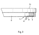
- FIG. 3 shows an enlarged detail from FIGS. 1 and 2.
- Each Disc 3, 4 has a radially arranged guide 17 for the Core drive 8, angular gear 8 'and mandrel 14 existing Rewinder 5, which by means of a drive, not shown, the can be pneumatic, hydraulic or electric motor, on the one hand radial can be pressed against the backup roller and on the other hand to remove a finished one Paper roll 16 or for attaching a new cardboard sleeve 9 radially after can be moved outside. Since the distance between the disks 3, 4, 3 ', 4' a certain web width is set, the mandrel 14 or else entire winding device 5 for attaching a cardboard tube 9 or Removal of a wound paper web 16 is axially displaceable his. Constructions familiar to the person skilled in the art can be used here without having to make almost any further explanations.
- the device according to the invention is used in such a way that one first winding device 5 of those involved in the winding process Disc pairs 3, 4, 3 ', 4' is equipped with a cardboard sleeve 9 that the Web starts of the paper web 15 cut to width on the cardboard sleeves 9 attached or wrapped and that then the support rollers 1, 2 and Cardboard tubes 9 by means of the associated drives at machine speed be started up.
- one not in the paper making process integrated slitter is the design speed of the Roll cutter or another one selected for the respective case Speed.
- an integrated in the paper manufacturing process Slitter in which the advantages of the invention really come into their own come, that's the web speed of papermaking.
- a third winding device 7 is a third winding device 7 and accordingly, a third working position is provided so that the attachment the third cardboard tube 9 and the removal of the first finished paper rolls can take place while the second roll is still being wound.
- the paper web 15 becomes transverse separated from the conveying direction and the new start of the path to the next Cardboard tube 9 wrapped, which of course beforehand Machine speed was accelerated. In the last position the wound paper webs 16 are braked and out of Take-up device removed, so that it is free to accommodate a new cardboard sleeve 9.
Abstract
Description
Die Erfindung betrifft eine Vorrichtung und ein Verfahren zum kontinuierlichen Aufwickeln von längsgeschnittenen Papierbahnen mit automatischem Rollenwechsel bei Maschinengeschwindigkeit.The invention relates to a device and a method for continuous winding of slit paper webs with automatic roll change Machine speed.
Eine derartige Vorrichtung ist aus der DE-B-1 474 243 bekannt.Such a device is known from DE-B-1 474 243.
Papier wird heute aus wirtschaftlichen Gründen in erheblichem Umfang kontinuierlich auf Produktionsmaschinen mit großer Arbeitsbreite hergestellt. Für die meisten Anwendungsfälle sind die erzeugten Papierbahnen zu breit und müssen daher auf brauchbare Abmessungen unterteilt werden. Dazu dienen sog. Rollenschneider.Paper is continuously being used to a considerable extent today for economic reasons Production machines manufactured with a large working width. For most applications the paper webs produced are too wide and must therefore have usable dimensions be divided. So-called winder are used for this.
Bei achslos aufzuwickelnden Papierbahnen, die aus längsgeschnittenen Teilbreiten einer auf der Produktionsmaschine hergestellten breiten Papierbahn bestehen, ist es bisher nicht möglich, die fertig aufgewickelten Teilbreiten-Rollen in der Aufwickeleinrichtung nach den Rollenschneidern bei Maschinengeschwindigkeit zu wechseln, wenn die ursprüngliche Papierbahn auch in der Länge unterteilt werden soll bzw. wenn Teilbreiten-Rollen mit kleinerem Durchmesser als bei der ursprünglichen Rolle hergestellt werden müssen. Das bedeutet, daß für jeden Rollenwechsel der Rollenschneider und die zugehörige Aufwickelvorrichtung heruntergefahren und stillgesetzt werden muß. Aus diesem Grunde kann der Rollenschneider auch nicht in die kontinuierliche Papierherstellung integriert werden. Er ist daher in jeder Papierfabrik die einzige diskontinuierlich arbeitende Maschine, die separat angeordnet ist und einen entsprechenden Ausschußanfall und Personalbedarf hat.In the case of paper webs which are to be wound up without an axle and which are made up of longitudinally cut sections exist on the wide paper web produced on the production machine, so far it is not possible, the fully wound section rolls in the rewinder to change the slitter at machine speed if the original one Paper web should also be subdivided in length or when using section rolls smaller diameter than the original roll. The means that for each roll change the slitter and the associated rewinder shutdown and shutdown. For this reason, the Winder also cannot be integrated into the continuous paper production. He is therefore the only discontinuously operating machine in every paper mill is arranged separately and has a corresponding amount of committee and personnel.
Es besteht somit die Aufgabe, im Hinblick auf eine gleichbleibende Produktqualität und auf die Integration des Rollenschneiders in den kontinuierlichen Papierherstellungsprozeß eine Vorrichtung und ein Verfahren vorzuschlagen, mit denen diese Ziele erreicht werden können und mit denen Ausschuß und Personalbedarf weiter reduziert werden können. It is therefore the task with regard to consistent product quality and on the integration of the roll cutter into the continuous papermaking process to propose a device and a method with which these goals are achieved can and with which committee and personnel requirements can be further reduced.
Zur Lösung wird eine Vorrichtung der eingangs genannten Art vorgeschlagen, die gekennzeichnet ist durch
- wenigstens zwei hinter einer Längsschneideeinrichtung separat angeordnete Stützwalzen,
- wenigstens je ein Scheibenpaar pro Stützwalze, die kontinuierlich zu den Stützwalzen angeordnet sind, unabhängig von den Stützwalzen drehbar gelagert sind und deren axialer Scheibenabstand auf die Breite der aufzuwickelnden Papierbahnen einstellbar ist,
- wenigstens zwei Aufwickelvorrichtungen pro Scheibenpaar, die in den Scheibenpaaren radial verstellbar geführt sind und je einen Kernantrieb für einzulegende Papphülsen umfassen sowie durch
- wenigstens eine Einrichtung zum Trennen einer auf Breite geschnittenen Papierbahn quer zur Förderrichtung und zum Anwickeln des neuen Bahnanfangs an einer auf Maschinengeschwindigkeit beschleunigten neuen Papphülse.
- at least two support rollers arranged separately behind a longitudinal cutting device,
- at least one pair of discs per support roller, which are arranged continuously to the support rollers, are rotatably mounted independently of the support rollers and whose axial disc spacing can be adjusted to the width of the paper webs to be wound,
- at least two winding devices per pair of discs, which are guided in the disc pairs in a radially adjustable manner and each comprise a core drive for cardboard tubes to be inserted, and by
- at least one device for separating a paper web cut to width transversely to the conveying direction and for winding the new beginning of the web on a new cardboard tube accelerated to machine speed.
Vorteilhafte Ausgestaltungen und Weiterbildungen der erfindungsgemäßen Vorrichtung sind in den Ansprüchen 2-10 beschrieben.Advantageous refinements and developments of the invention Device are described in claims 2-10.
Das Verfahren zum kontinuierlichen Aufwickeln von längsgeschnittenen Papierbahnen mit automatischem Rollenwechsel bei Maschinengeschwindigkeit mittels einer Vorrichtung nach einem der Ansprüche 1-10 ist dadurch gekennzeichnet, daß je eine erste Aufwickelvorrichtung der am Aufwickelvorgang beteiligten Scheibenpaare mit einer Papphülse bestückt wird, daß die Bahnanfänge der auf Breite geschnittenen Papierbahnen an den Papphülsen befestigt bzw. angewickelt werden, daß die Stützwalzen und die Papphülsen auf Maschinengeschwindigkeit hochgefahren werden, daß die Scheiben während des Aufwickelvorganges in die nächste Position weitergedreht werden, daß je eine zweite Aufwickelvorrichtung mit einer Papphülse bestückt wird, daß die Papphülsen auf Maschinengeschwindigkeit beschleunigt werden, daß bei Erreichen des gewünschten Wickeldurchmessers die Papierbahn quer zur Förderrichtung abgetrennt und der neue Bahnanfang auf der zweiten Papphülse angewickelt wird, daß die Scheibenpaare während des Aufwickelvorganges in die nächste Position gedreht werden und daß die aufgewickelte Papierbahn abgebremst, aus der ersten Aufwickelvorrichtung entnommen und letztere mit einer neuen Papphülse bestückt wird.The process for the continuous winding of slit Paper webs with automatic roll change at machine speed by means of a device according to any one of claims 1-10 characterized in that a first winding device on Pairs of disks involved in the winding process are fitted with a cardboard tube, that the web starts of the paper webs cut to width on the Cardboard tubes are attached or wound that the backup rollers and the Cardboard cores are run up to machine speed that the Discs in the next position during the winding process be rotated further that a second winding device with a Cardboard tube is loaded that the cardboard tubes at machine speed be accelerated that when the desired winding diameter is reached the paper web cut off transversely to the conveying direction and the new beginning of the web is wound on the second cardboard tube that the disc pairs during of the winding process to the next position and that the wound paper web braked, from the first winding device removed and the latter is fitted with a new cardboard tube.
Vorteilhafte Abwandlungen dieser Verfahrensmaßnahmen sind in den
Ansprüchen 12 und 13 beschrieben.Advantageous modifications of these procedural measures are in the
Weitere Einzelheiten werden anhand der in den Figuren 1 bis 3 dargestellten Ausführungsbeispiele näher erläutert. Es zeigen:
- Fig. 1
- eine Draufsicht eines ersten Ausführungsbeispiels der Erfindung mit je zwei Aufwickelvorrichtungen pro Scheibenpaar,
- Fig. 2
- eine Seitenansicht von einem zweiten Ausführungsbeispiel der Erfindung mit je drei Aufwickelvorrichtungen pro Scheibenpaar, und
- Fig. 3
- eine Einzelheit der Aufwickelvorrichtung.
- Fig. 1
- 2 shows a plan view of a first exemplary embodiment of the invention, each with two winding devices per pair of disks,
- Fig. 2
- a side view of a second embodiment of the invention, each with three winding devices per pair of discs, and
- Fig. 3
- a detail of the winder.
Das Ausführungsbeispiel gemäß Fig. 1 umfaßt zwei in Transportrichtung der
Papierbahn 15 hintereinander angeordnete Stützwalzen 1, 2, die in üblicher
Weise in einem Maschinengestell zueinander ausgerichtet und drehbar gelagert
angeordnet sind. Einzelheiten der Lagerung und der Antriebe der Stützwalzen
sind nicht dargestellt, um die zur Erfindung gehörenden Merkmale deutlicher
hervortreten zu lassen. Zu jeder Stützwalze 1, 2 gehört ein Scheibenpaar 3, 4
bzw. 3', 4', das konzentrisch zu den Stützwalzen 1, 2 und unabhängig von
diesen drehbar gelagert ist und dessen axialer Abstand auf die Breite der
aufzuwickelnden Papierbahnen 15 einstellbar ist. Im dargestellten Beispiel ist
eine ursprüngliche Papierbahn von der Breite der Papierherstellungsmaschine
auf einen nicht dargestellten Rollenschneider in zwei gleichbreite Papierbahnen
15 längsgeschnitten, wobei die linke Papierbahn von der in Förderrichtung
gesehen ersten Aufwickelvorrichtung 5, 6 aufgewickelt wird und die rechte auf
der zweiten Aufwickelvorrichtung 5, 6. Antrieb und Lagerung der
Scheibenpaare 3, 4 bzw. 3', 4' sind aus den bereits genannten Gründen nicht
dargestellt.The embodiment of FIG. 1 includes two in the transport
Das Ausführungsbeispiel ist auch insoweit vereinfacht, als die Gesamtanlage
nur für zwei Papierbahnen 15 konzipiert ist. Selbstverständlich lassen sich die
Stützwalzen 1, 2 länger ausführen bzw. es lassen sich pro Stützwalze 1, 2 zwei
oder mehr Scheibenpaare 3, 4, 3', 4' anordnen, wenn die ursprüngliche
Papierbahn breiter ist als dargestellt oder aber in mehr als zwei Papierbahnen
aufgetrennt werden soll. In dem Fall werden die Scheibenpaare quer zur
Papierbahn in der Weise versetzt angeordnet, daß die Aufwickelvorrichtungen
für die erste, dritte, fünfte usw. Papierbahn mit der einen Stützwalze 1
zusammenarbeiten und die Aufwickelvorrichtungen für die zweite, vierte,
sechste usw. Papierbahn mit der anderen Stützwalze 2.The exemplary embodiment is also simplified insofar as the overall system
is only designed for two
Sollen verhältnismäßig schmale Papierbahnen aufgewickelt werden, reicht u.U. die Breite zur Unterbringung der Scheibenpaare und der Aufwickelvorrichtungen nicht aus. Für solche Fälle kann das dargestellte Ausführungsbeispiel auch in der Weise abgewandelt werden, daß mehr als zwei Stützwalzen vorgesehen werden und daß die Papierbahnen einer ersten, einer zweiten und einer dritten Stützwalze zugeordnet werden.If relatively narrow paper webs are to be wound up, it may be sufficient the width to accommodate the pairs of discs and the Rewinder not out. For such cases this can be shown Embodiment can also be modified in such a way that more than two back-up rollers are provided and that the paper webs a first, a second and be assigned to a third backup roller.
Bei dem in Fig. 1 dargestellten Ausführungsbeispiel sind pro Scheibenpaar 3,
4, 3', 4' je zwei um 180° zueinander versetzt angeordnete
Aufwickelvorrichtungen 5, 6 vorgesehen. Sie sind in je einer linken und einer
rechten Führung 17 gelagert, so daß es möglich ist, sie radial zu verstellen,
wofür bekannte pneumatische, hydraulische oder elektromotorische Antriebe
verwendet werden können. Dabei ist der Durchmesser der Scheibenpaare 3, 4,
3', 4' so gewählt, daß der größtmögliche Durchmesser einer aufgewickelten
Papierbahn 16 stets innerhalb des äußeren Umfangs 11 bleibt, damit die
Scheibenpaare 3, 4, 4', 4' an dem zu ihrer Lagerung erforderlichen
Maschinengestell vorbeigeschwenkt werden können. Lediglich in der
Entnahmeposition können die aufgewickelten Papierbahnen 16 radial weiter
nach außen verstellbar sein.In the exemplary embodiment shown in FIG. 1, 3,
4, 3 ', 4' each arranged two offset by 180 ° to each
Im oberen Teil der Darstellung ist die Aufwickelvorrichtung 5 mit aufgesetzter
Papphülse 9 gezeigt, während im unteren Teil die Dorne 14 der
Aufwickelvorrichtung 5 zu sehen sind. Die jeweils unteren
Aufwickelvorrichtungen 6 tragen eine fertig aufgewickelte Papierbahn 16.
Gestrichelt sind die Ränder der Papierbahnen 15 angedeutet, die unterhalb der
erfindungsgemäßen Vorrichtung zugeführt werden.In the upper part of the illustration, the
In Fig. 2 ist ein Ausführungsbeispiel der Erfindung mit zwei Stützwalzen 1
und 2 und zwei Scheibenpaaren 3, 4, 3', 4' dargestellt, wobei im Unterschied
zu Fig. 1 je drei Aufwickelvorrichtungen 5, 6, 7 mit Kernantrieben 8
vorgesehen sind. Dementsprechend hat diese Vorrichtung drei verschiedene
Arbeitspositionen, unterscheidet sich im übrigen aber nicht von dem Beispiel
gemäß Fig. 1.2 shows an embodiment of the invention with two
Angedeutet ist noch das Maschinengestell 12 mit dem Antrieb 13 für die
Scheibenpaare 3, 4, 3', 4', wobei das Maschinengestell 12 auch zur Lagerung
der Stützwalzen 1 und 2 dient und nicht dargestellte Einrichtungen umfaßt,
mittels derer der Abstand der Scheiben 3, 4 bzw. 3', 4' zueinander auf die
jeweils gewünschte Breite der aufzuwickelnden Papierbahnen 15 einstellbar ist.
Einzelheiten der Lagerung und Einstellvorrichtungen sind nicht dargestellt.The
Angedeutet ist ferner eine an sich bekannte Einrichtung 10 zum Trennen einer
auf Breite geschnittenen Papierbahn 15 quer zur Förderrichtung und zum
Anwickeln des neuen Bahnanfangs an eine auf Maschinengeschwindigkeit
beschleunigte Papphülse 9. Die Einrichtung 10 ist radial zwischen die
Scheibenpaare 3, 4, 3', 4' ein- und ausfahrbar. Sie arbeitet in bekannter Weise
mit einem Preßluftimpuls, der die Papierbahn durchtrennt und den neuen
Bahnanfang gegen die leere Papphülse 9 anbläst, die zweckmäßigerweise mit
einem Klebstoff geschichtet ist, damit der Anwickelvorgang ohne Störungen
verlaufen kann.Also indicated is a
Eine fertig aufgewickelte Papierrolle 16 wird zweckmäßigerweise unten in der
dargestellten Position zwischen den beiden sich parallel zur Stützwalzenachse
erstreckenden Führungen des Maschinengestells 12 für die Scheibenpaare
entnommen, wozu die aufgewickelte Papierbahn 16 radial weiter nach außen
verfahrbar ist als beim Aufwickeln und Schwenken der Scheibenpaare 3, 4 3',
4' beim Wechseln der Arbeitspositionen.A fully
Fig. 3 zeigt noch einen vergrößerten Ausschnitt aus den Fig. 1 und 2. Jede
Scheibe 3, 4 besitzt eine radial angeordnete Führung 17 für die aus
Kernantrieb 8, Winkelgetriebe 8' und Dorn 14 bestehende
Aufwickelvorrichtung 5, die mittels eines nicht dargestellten Antriebs, der
pneumatisch, hydraulisch oder elektromotorisch sein kann, einerseits radial
gegen die Stützwalze andrückbar und andererseits zur Entnahme einer fertigen
Papierrolle 16 bzw. zum Aufstecken einer neuen Papphülse 9 radial nach
außen verfahren werden kann. Da der Abstand der Scheiben 3, 4, 3', 4' auf
eine bestimmte Bahnbreite cingestellt ist, muß der Dorn 14 oder aber die
gesamte Aufwickelvorrichtung 5 zum Aufstecken einer Papphülse 9 bzw. zur
Entnahme einer aufgewickelten Papierbahn 16 axial verschieblich ausgeführt
sein. Dabei können dem Fachmann geläufige Konstruktionen verwendet
werden, ohne daß nahezu weitere Ausführungen gemacht werden müßten.FIG. 3 shows an enlarged detail from FIGS. 1 and 2. Each
Die erfindungsgemäße Vorrichtung wird in der Weise benutzt, daß je eine
erste Aufwickelvorrichtung 5 der am Aufwickelvorgang beteiligten
Scheibenpaare 3, 4, 3', 4' mit einer Papphülse 9 bestückt wird, daß die
Bahnanfänge der auf Breite geschnittenen Papierbahn 15 an den Papphülsen 9
befestigt bzw. angewickelt werden und daß dann die Stützwalzen 1, 2 und die
Papphülsen 9 mittels der zugehörigen Antriebe auf Maschinengeschwindigkeit
hochgefahren werden. Bei einem nicht in den Papierherstellungsprozeß
integrierten Rollenschneider ist das die Auslegungsgeschwindigkeit des
Rollenschneiders oder aber eine andere für den jeweiligen Fall ausgewählte
Geschwindigkeit. Bei einem in den Papierherstellungsprozeß integrierten
Rollenschneider, bei dem die Vorteile der Erfindung richtig zur Geltung
kommen, ist das die Bahngeschwindigkeit der Papierherstellung.The device according to the invention is used in such a way that one
first winding
Während die Papierbahnen 15 auf die jeweils ersten Papphülsen 9 aufgewickelt
werden, können die Scheibenpaare 3, 4, 3', 4' in die nächste Position
weitergedreht werden, d.h. beim Ausführungsbeispiel nach Fig. 1 um 180°
und beim Ausführungsbeispiel gemäß Fig. 2 um 120°. In dieser Position
werden die nächsten Aufwickelvorrichtungen 6 mit Papphülsen 9 bestückt.
Dies ist bei Fig. 1 gleichzeitig die Position, in der die fertig aufgewickelten
Papierbahnen 16 aus der Vorrichtung entnommen werden.While the
Gemäß Fig. 2 ist noch eine dritte Aufwickelvorrichtung 7 und
dementsprechend eine dritte Arbeitsposition vorgesehen, so daß das Aufstecken
der dritten Papphülse 9 und die Entnahme der ersten fertigen Papierrollen
erfolgen kann, während die zweite Rolle noch aufgewickelt wird. Damit sind
organisatorische Vorteile und eine zweckmäßige Entzerrung der
Arbeitsvorgänge verbunden.2 is a third winding
Ist ein vorgesehener Rollendurchmesser erreicht, wird die Papierbahn 15 quer
zur Förderrichtung abgetrennt und der neue Bahnanfang auf die jeweils nächste
Papphülse 9 angewickelt, die selbstverständlich zuvor auf
Maschinengeschwindigkeit beschleunigt wurde. In der jeweils letzten Position
werden die fertig aufgewickelten Papierbahnen 16 abgebremst und aus der
Aufwickelvorrichtung entnommen, so daß diese frei ist für die Aufnahme einer
neuen Papphülse 9.If an intended roll diameter is reached, the
Durch die Anordnung von zwei oder mehr Aufwickelvorrichtungen in einem
koaxial zu den Stützwalzen gelagerten Scheibenpaar ist es möglich, den
Rollenschneider kontinuierlich zu betreiben, weil auf Breite geschnittene
Papierbahnen 15 beliebiger Länge aufgewickelt werden können, ohne daß der
Aufwickelvorgang unterbrochen werden muß. Neue Papphülsen können nach
dem Revolverprinzip eingebracht, beschleunigt und in eine Position gebracht
werden, in der sie den jeweils mit Maschinengeschwindigkeit bewegten neuen
Bahnanfang aufnehmen können. Damit ist es möglich geworden, den
Rollenschneider in den weitgehend automatisierten Papierherstellungsprozeß zu
integrieren. Man muß das Schneiden auf vorgegebene Bahnbreiten also nicht
mehr "chargenweise" mit mehrfachem An- und Abfahren des Rollenschneiders
betreiben und verringert somit nicht nur den Ausschuß, sondern auch den
Personalbedarf. Damit ist es möglich, Papierbahnen beliebiger Breite und
Länge unmittelbar im Anschluß an die breiten, kontinuierlich arbeitenden
Papierherstellungsmaschinen zu erzeugen, d.h. aus der aus wirtschaftlichen
Gründen sehr breiten und praktisch endlos hergestellten ursprünglichen
Papierbahn können Papierbahnen in allen gewünschten Breiten und Längen
hergestellt werden, ohne daß ein Zwischenaufwickeln erforderlich ist und ohne
daß ein separat, d.h. außerhalb der eigentlichen Fertigungslinie angeordneter,
nur chargenweise betreibbarer Rollenschneider erforderlich ist. Der
Rollenschneider kann vielmehr vollständig in die Papierherstellung integriert
werden.By arranging two or more winding devices in one
coaxial to the support rollers pair of discs it is possible to
Operate slitter continuously because it is cut to
Claims (13)
- Apparatus for the continuous winding of longitudinally cut paper webs with automatic roll change at machine speed, with at least two supporting rollers (1, 2) arranged separately behind a longitudinal cutting device, characterised byat least one pair of discs (3, 4, 3', 4') to each supporting roller (1, 2), which are arranged concentrically with the supporting rollers (1, 2) and mounted rotatably independently of the supporting rollers (1, 2) and whose axial distance between discs is adjustable to the width of the paper webs (15) to be wound,at least two winding devices (5, 6, 7) to every pair of discs (3, 4, 3', 4'), which are guided radially displaceably in the pairs of discs (3, 4, 3', 4') and each include a core drive (8) for cardboard tubes (9) to be inserted, and byat least one device (10) for separating a paper web (15) cut to width, transversely to the direction of conveying, and for initially winding the new web beginning on a new cardboard tube (9) accelerated to machine speed.
- Apparatus according to claim 1, characterised in that three winding devices (5, 6, 7) offset from each other by 120° are provided for each pair of discs (3, 4, 3', 4').
- Apparatus according to claim 1 or 2, characterised in that the supporting rollers (1, 2) are arranged at the same level one behind the other in the direction of conveying the paper webs (15) and in that their pairs of discs (3, 4, 3', 4') are offset from each other transversely to the direction of conveying.
- Apparatus according to any of claims 1 to 3, characterised in that for every supporting roller (1, 2), preferably for every pair of discs (3, 4, 3', 4'), a device (10) for separating and initial winding is provided.
- Apparatus according to any of claims 1 to 4, characterised in that the supporting rollers (1, 2) have a torque-controlled or web tension-controlled drive.
- Apparatus according to any of claims 1 to 5, characterised in that the pairs of discs (3, 4, 3', 4') are mounted and guided at their outer circumference (11).
- Apparatus according to claim 6, characterised in that the pairs of discs (3, 4, 3', 4') are mounted in a machine frame (12) in which are also mounted the supporting rollers (1, 2).
- Apparatus according to claim 6 or 7, characterised in that the pairs of discs (3, 4, 3', 4') have their own drive (13) for pivoting the winding devices (5, 6, 7) into different positions.
- Apparatus according to any of claims 1 to 8, characterised in that the winding devices (5, 6, 7) can be pressed radially inwards against the supporting rollers (1, 2).
- Apparatus according to any of claims 1 to 9, characterised in that the winding devices (5, 6, 7) have mandrels (14) for fitting the cardboard tubes (9) on.
- Method for the continuous winding of longitudinally cut paper webs (15) with automatic roll change at machine speed, by means of an apparatus according to any of claims 1 to 10, characterised in that in each case a first winding device (5) of the pairs of discs (3, 4, 3', 4') involved in the winding operation is fitted with a cardboard tube (9), in that the web beginnings of the paper webs (15) cut to width are attached to or initially wound on the cardboard tubes (9), in that the supporting rollers (1, 2) and the cardboard tubes (9) are brought up to machine speed, in that the discs (3, 4, 3', 4') during the winding operation are rotated on to the next position, in that in each case a second winding device (6) is fitted with a cardboard tube (9), in that the cardboard tubes (9) are accelerated to machine speed, in that on reaching the desired roll diameter the paper web (15) is separated transversely to the direction of conveying and the new web beginning is initially wound on the second cardboard tube (9), in that the pairs of discs (3, 4, 3', 4') during the winding operation are rotated to the next position and in that the wound paper web (16) is braked and removed from the first winding device (5) and the latter is fitted with a new cardboard tube (9).
- Method according to claim 11, but with the proviso that in an apparatus with three winding devices (5, 6, 7) to each pair of discs (3, 4, 3', 4') the latter are successively rotated into three positions offset from each other by 120°, the first position being used to fit a new cardboard tube (9), the second position to wind the paper webs (15) and the third to brake and remove the wound paper web (16).
- Method according to claim 11 or 12, characterised in that the change of position of all the pairs of discs (3, 4, 3', 4') involved and in particular initial winding onto a new cardboard tube (9) is carried out simultaneously on the different supporting rollers (1, 2).
Applications Claiming Priority (3)
| Application Number | Priority Date | Filing Date | Title |
|---|---|---|---|
| DE19609802 | 1996-03-13 | ||
| DE19609802A DE19609802A1 (en) | 1996-03-13 | 1996-03-13 | Device for the continuous reeling of slit paper webs with automatic reel change at machine speed |
| PCT/EP1997/001271 WO1997033821A1 (en) | 1996-03-13 | 1997-03-13 | Device for continuously winding up longitudinally cut paper webs with rolls changed automatically at the machine speed |
Publications (2)
| Publication Number | Publication Date |
|---|---|
| EP0886620A1 EP0886620A1 (en) | 1998-12-30 |
| EP0886620B1 true EP0886620B1 (en) | 2000-01-19 |
Family
ID=7788125
Family Applications (1)
| Application Number | Title | Priority Date | Filing Date |
|---|---|---|---|
| EP97907097A Expired - Lifetime EP0886620B1 (en) | 1996-03-13 | 1997-03-13 | Device for continuously winding up longitudinally cut paper webs with rolls changed automatically at the machine speed |
Country Status (4)
| Country | Link |
|---|---|
| US (1) | US6406417B1 (en) |
| EP (1) | EP0886620B1 (en) |
| DE (2) | DE19609802A1 (en) |
| WO (1) | WO1997033821A1 (en) |
Families Citing this family (4)
| Publication number | Priority date | Publication date | Assignee | Title |
|---|---|---|---|---|
| US6709549B2 (en) * | 2001-03-29 | 2004-03-23 | Metso Paper Karlstad Ab | Multi-reel apparatus in a paper machine |
| ITFI20030118A1 (en) * | 2003-04-28 | 2004-10-29 | Fabio Perini | DEVICE AND METHOD TO CAUSE THE TAPPING OF PAPER TAPES IN REWINDING MACHINES |
| DE102009001171A1 (en) * | 2009-02-26 | 2010-09-02 | Voith Patent Gmbh | Arrangement of roll cutting device and method for operating an arrangement of roll cutting device |
| CH705226A2 (en) * | 2011-07-05 | 2013-01-15 | Swiss Winding Inventing Ag | Winder. |
Family Cites Families (19)
| Publication number | Priority date | Publication date | Assignee | Title |
|---|---|---|---|---|
| US2201233A (en) | 1937-09-10 | 1940-05-21 | Cameron Machine Co | Means for controlling the power drive in a winding or other machine |
| US2200000A (en) * | 1937-09-10 | 1940-05-07 | Cameron Machine Co | Art of winding flexible material |
| DE1091856B (en) * | 1957-12-18 | 1960-10-27 | Jagenberg Werke Ag | Device for longitudinal cutting and rolling up paper webs coming directly from the paper machine |
| DE1474243B1 (en) * | 1964-12-24 | 1969-12-18 | Goebel Gmbh Maschf | Machine for the uninterrupted winding of a lengthwise cut web |
| US3433429A (en) * | 1967-04-10 | 1969-03-18 | Midland Ross Corp | Film winding apparatus |
| DE1952205C3 (en) * | 1968-10-17 | 1973-10-31 | Inta-Roto, Inc., Richmond, Va. (V.St.A.) | Method for the automatic continuous winding up endlessly the web-shaped goods, in particular from several juxtaposed partial webs existing goods, and device for carrying out the same |
| US3599888A (en) | 1969-09-08 | 1971-08-17 | Inta Roto Inc | Method of and means for severing web strip material upon completion of winding a roll and initiating winding of a new roll |
| DE7012648U (en) | 1970-04-07 | 1970-08-27 | Rotomec Spa | WINDING DEVICE. |
| FR2098606A5 (en) | 1970-07-16 | 1972-03-10 | Riegger Paul | |
| DE8019261U1 (en) | 1980-07-18 | 1982-01-21 | Jagenberg-Werke AG, 4000 Düsseldorf | DEVICE FOR SEPARATE REWINDING OF LONG-SIDED SHEETS |
| FI811789L (en) * | 1980-07-18 | 1982-01-19 | Jagenberg Werke Ag | ANORDING FOR SEPARATE UPPLINDNING AV LAENGSGAOENDE BANOR |
| DE3418741C2 (en) * | 1984-05-19 | 1986-06-19 | Erwin Kampf Gmbh & Co Maschinenfabrik, 5276 Wiehl | Cutting and winding machine |
| DE3645252C2 (en) * | 1986-04-28 | 1995-02-09 | Windmoeller & Hoelscher | Device for winding a plurality of narrow material webs formed by longitudinally cutting a wide material web into supply rolls |
| DE3636685C2 (en) | 1986-04-28 | 1994-04-07 | Windmoeller & Hoelscher | Device for winding a plurality of narrow material webs formed by longitudinally cutting a wide material web into supply rolls |
| IT1189496B (en) * | 1986-05-09 | 1988-02-04 | Meccanica Comasca Srl | REWINDER CUTTING MACHINE FOR ADHESIVE AND NON-ADHESIVE TAPES HAVING AT LEAST FOUR DISTINCT REWINDING GROUPS |
| US5217177A (en) * | 1989-11-02 | 1993-06-08 | Ghezzi & Annoni S.P.A. | Machine with continuous operating cycle for the packaging in rolls of various strip-shaped materials by means of a plurality of simultaneous longitudinal cuts of a wide strip of material fed by a roller |
| DE4200478A1 (en) | 1991-10-24 | 1993-04-29 | Windmoeller & Hoelscher | DEVICE FOR WINDING MATERIAL COATINGS ON REEL SHAFTS |
| DE4232363C2 (en) * | 1992-09-26 | 1995-11-30 | Kloeckner Er We Pa Gmbh | Device for the continuous winding of material webs |
| DE9413238U1 (en) * | 1994-08-17 | 1994-10-13 | Reinhold Klaus | Device for winding material webs with a cutting and transport roller |
-
1996
- 1996-03-13 DE DE19609802A patent/DE19609802A1/en not_active Withdrawn
-
1997
- 1997-03-13 US US09/101,704 patent/US6406417B1/en not_active Expired - Fee Related
- 1997-03-13 DE DE59701038T patent/DE59701038D1/en not_active Expired - Lifetime
- 1997-03-13 EP EP97907097A patent/EP0886620B1/en not_active Expired - Lifetime
- 1997-03-13 WO PCT/EP1997/001271 patent/WO1997033821A1/en active IP Right Grant
Also Published As
| Publication number | Publication date |
|---|---|
| WO1997033821A1 (en) | 1997-09-18 |
| EP0886620A1 (en) | 1998-12-30 |
| DE19609802A1 (en) | 1997-09-18 |
| DE59701038D1 (en) | 2000-02-24 |
| US6406417B1 (en) | 2002-06-18 |
Similar Documents
| Publication | Publication Date | Title |
|---|---|---|
| EP0145029B1 (en) | Winding or unwinding device with a plurality of mandrels in cascade | |
| DE10035894B4 (en) | Winding device for strip material | |
| EP0744365B1 (en) | Method for changing the roll in a winding machine and winding machine for carrying out this method | |
| DE4401804A1 (en) | Method of winding length of paper onto reel | |
| EP2223876B1 (en) | Slitter rewinder arrangement and method for operating a slitter rewinder arrangement | |
| EP0886620B1 (en) | Device for continuously winding up longitudinally cut paper webs with rolls changed automatically at the machine speed | |
| DE60200291T2 (en) | Wrapping machine with flanks for carrying cross-dowels moving along a closed path | |
| EP2184243B1 (en) | Method for winding material web and device for executing the method | |
| EP1657194B1 (en) | Reel winding device and method for winding reels | |
| EP1179630B1 (en) | Method and device for making paper rolls | |
| EP2088106B1 (en) | Coiling machine for winding a web of material | |
| EP1657193B1 (en) | Reel winding device and method for winding reels | |
| EP2082982B1 (en) | Coiling device | |
| DE202006020888U1 (en) | Device for winding at least two webs of material | |
| EP1842815A1 (en) | Installation for paper production | |
| DE102019111475B4 (en) | unwind station | |
| EP0896940A1 (en) | Winding apparatus, in particular in a slitter rewinder | |
| EP1652803B1 (en) | Winding method | |
| EP3368455B1 (en) | Winding machine for web-type materials, and method for winding a web-type material onto winding tubes/cores | |
| EP0873940B1 (en) | Roll cutting device with a packaging means | |
| DE19720174B4 (en) | calender | |
| EP1038814B1 (en) | Winding system for webs of duroplastic compound | |
| EP1291308B1 (en) | Device for winding material web into rolls | |
| DE60015144T2 (en) | METHOD FOR CONTINUOUSLY WRAPPING PAPER AND WRAPPER | |
| DE10048327B4 (en) | Method for winding a paper web and winding device for paper web |
Legal Events
| Date | Code | Title | Description |
|---|---|---|---|
| PUAI | Public reference made under article 153(3) epc to a published international application that has entered the european phase |
Free format text: ORIGINAL CODE: 0009012 |
|
| 17P | Request for examination filed |
Effective date: 19980528 |
|
| AK | Designated contracting states |
Kind code of ref document: A1 Designated state(s): DE FI FR GB |
|
| RAP1 | Party data changed (applicant data changed or rights of an application transferred) |
Owner name: VOITH SULZER PAPIERTECHNIK PATENT GMBH |
|
| GRAG | Despatch of communication of intention to grant |
Free format text: ORIGINAL CODE: EPIDOS AGRA |
|
| GRAG | Despatch of communication of intention to grant |
Free format text: ORIGINAL CODE: EPIDOS AGRA |
|
| GRAH | Despatch of communication of intention to grant a patent |
Free format text: ORIGINAL CODE: EPIDOS IGRA |
|
| 17Q | First examination report despatched |
Effective date: 19990607 |
|
| GRAH | Despatch of communication of intention to grant a patent |
Free format text: ORIGINAL CODE: EPIDOS IGRA |
|
| GRAA | (expected) grant |
Free format text: ORIGINAL CODE: 0009210 |
|
| AK | Designated contracting states |
Kind code of ref document: B1 Designated state(s): DE FI FR GB |
|
| GBT | Gb: translation of ep patent filed (gb section 77(6)(a)/1977) |
Effective date: 20000119 |
|
| REF | Corresponds to: |
Ref document number: 59701038 Country of ref document: DE Date of ref document: 20000224 |
|
| ET | Fr: translation filed | ||
| PLBE | No opposition filed within time limit |
Free format text: ORIGINAL CODE: 0009261 |
|
| STAA | Information on the status of an ep patent application or granted ep patent |
Free format text: STATUS: NO OPPOSITION FILED WITHIN TIME LIMIT |
|
| 26N | No opposition filed | ||
| REG | Reference to a national code |
Ref country code: GB Ref legal event code: IF02 |
|
| PGFP | Annual fee paid to national office [announced via postgrant information from national office to epo] |
Ref country code: GB Payment date: 20030224 Year of fee payment: 7 |
|
| PGFP | Annual fee paid to national office [announced via postgrant information from national office to epo] |
Ref country code: FR Payment date: 20030320 Year of fee payment: 7 |
|
| PG25 | Lapsed in a contracting state [announced via postgrant information from national office to epo] |
Ref country code: GB Free format text: LAPSE BECAUSE OF NON-PAYMENT OF DUE FEES Effective date: 20040313 |
|
| GBPC | Gb: european patent ceased through non-payment of renewal fee |
Effective date: 20040313 |
|
| PG25 | Lapsed in a contracting state [announced via postgrant information from national office to epo] |
Ref country code: FR Free format text: LAPSE BECAUSE OF NON-PAYMENT OF DUE FEES Effective date: 20041130 |
|
| REG | Reference to a national code |
Ref country code: FR Ref legal event code: ST |
|
| PGFP | Annual fee paid to national office [announced via postgrant information from national office to epo] |
Ref country code: FI Payment date: 20050311 Year of fee payment: 9 |
|
| PG25 | Lapsed in a contracting state [announced via postgrant information from national office to epo] |
Ref country code: FI Free format text: LAPSE BECAUSE OF NON-PAYMENT OF DUE FEES Effective date: 20060313 |
|
| PGFP | Annual fee paid to national office [announced via postgrant information from national office to epo] |
Ref country code: DE Payment date: 20100324 Year of fee payment: 14 |
|
| PG25 | Lapsed in a contracting state [announced via postgrant information from national office to epo] |
Ref country code: DE Free format text: LAPSE BECAUSE OF NON-PAYMENT OF DUE FEES Effective date: 20111001 |
|
| REG | Reference to a national code |
Ref country code: DE Ref legal event code: R119 Ref document number: 59701038 Country of ref document: DE Effective date: 20111001 |