EP0886620B1 - Dispositif d'enroulement continu de bandes de papier coupees longitudinalement avec changement automatique des rouleaux a vitesse de la machine - Google Patents
Dispositif d'enroulement continu de bandes de papier coupees longitudinalement avec changement automatique des rouleaux a vitesse de la machine Download PDFInfo
- Publication number
- EP0886620B1 EP0886620B1 EP97907097A EP97907097A EP0886620B1 EP 0886620 B1 EP0886620 B1 EP 0886620B1 EP 97907097 A EP97907097 A EP 97907097A EP 97907097 A EP97907097 A EP 97907097A EP 0886620 B1 EP0886620 B1 EP 0886620B1
- Authority
- EP
- European Patent Office
- Prior art keywords
- winding
- discs
- pairs
- paper webs
- web
- Prior art date
- Legal status (The legal status is an assumption and is not a legal conclusion. Google has not performed a legal analysis and makes no representation as to the accuracy of the status listed.)
- Expired - Lifetime
Links
Images
Classifications
-
- B—PERFORMING OPERATIONS; TRANSPORTING
- B65—CONVEYING; PACKING; STORING; HANDLING THIN OR FILAMENTARY MATERIAL
- B65H—HANDLING THIN OR FILAMENTARY MATERIAL, e.g. SHEETS, WEBS, CABLES
- B65H18/00—Winding webs
- B65H18/02—Supporting web roll
- B65H18/021—Multiple web roll supports
- B65H18/0212—Turrets
-
- B—PERFORMING OPERATIONS; TRANSPORTING
- B65—CONVEYING; PACKING; STORING; HANDLING THIN OR FILAMENTARY MATERIAL
- B65H—HANDLING THIN OR FILAMENTARY MATERIAL, e.g. SHEETS, WEBS, CABLES
- B65H19/00—Changing the web roll
- B65H19/22—Changing the web roll in winding mechanisms or in connection with winding operations
- B65H19/2284—Simultaneous winding at several stations, e.g. slitter-rewinders
-
- B—PERFORMING OPERATIONS; TRANSPORTING
- B65—CONVEYING; PACKING; STORING; HANDLING THIN OR FILAMENTARY MATERIAL
- B65H—HANDLING THIN OR FILAMENTARY MATERIAL, e.g. SHEETS, WEBS, CABLES
- B65H2301/00—Handling processes for sheets or webs
- B65H2301/40—Type of handling process
- B65H2301/41—Winding, unwinding
- B65H2301/414—Winding
- B65H2301/4148—Winding slitting
-
- B—PERFORMING OPERATIONS; TRANSPORTING
- B65—CONVEYING; PACKING; STORING; HANDLING THIN OR FILAMENTARY MATERIAL
- B65H—HANDLING THIN OR FILAMENTARY MATERIAL, e.g. SHEETS, WEBS, CABLES
- B65H2408/00—Specific machines
- B65H2408/20—Specific machines for handling web(s)
- B65H2408/23—Winding machines
- B65H2408/231—Turret winders
- B65H2408/2315—Turret winders specified by number of arms
- B65H2408/23155—Turret winders specified by number of arms with three arms
Definitions
- the invention relates to a device and a method for continuous winding of slit paper webs with automatic roll change Machine speed.
- Such a device is known from DE-B-1 474 243.
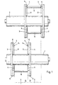
- FIG. 1 includes two in the transport direction Paper web 15 support rollers 1, 2 arranged one behind the other in the usual Aligned in a machine frame and rotatably mounted are arranged. Details of the storage and drives of the backup rolls are not shown to clarify the features belonging to the invention to emerge.
- a pair of disks 3, 4 belongs to each support roller 1, 2 or 3 ', 4', which is concentric with the support rollers 1, 2 and independent of this is rotatably mounted and its axial distance to the width of the paper webs 15 to be wound is adjustable.
- the exemplary embodiment is also simplified insofar as the overall system is only designed for two paper webs 15.
- Support rollers 1, 2 run longer or two can be used for each support roller 1, 2 or more pairs of discs 3, 4, 3 ', 4' if the original Paper web is wider than shown or in more than two paper webs to be separated.
- the disc pairs are transverse to Paper web staggered in such a way that the winding devices for the first, third, fifth, etc. paper web with the one support roller 1 work together and the rewinder for the second, fourth, sixth etc. paper web with the other backup roller 2.
- Embodiment can also be modified in such a way that more than two back-up rollers are provided and that the paper webs a first, a second and be assigned to a third backup roller.
- 3 ', 4' each arranged two offset by 180 ° to each other Winding devices 5, 6 are provided. They are in left and one each right guide 17 mounted so that it is possible to adjust it radially, for which known pneumatic, hydraulic or electric motor drives can be used.
- the diameter of the disk pairs 3, 4, 3 ', 4' chosen so that the largest possible diameter of a wound Paper web 16 always remains within the outer circumference 11 so that the Disc pairs 3, 4, 4 ', 4' on the necessary for their storage Machine frame can be swung past. Only in the Removal position, the wound paper webs 16 can continue radially be adjustable to the outside.
- the winding device 5 is attached Cardboard sleeve 9 shown, while the mandrels 14 in the lower part Winding device 5 can be seen.
- the bottom one Winding devices 6 carry a completely wound paper web 16. Dashed lines indicate the edges of the paper webs 15, which are below the device according to the invention are supplied.
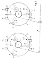
- FIG. 2 shows an embodiment of the invention with two support rollers 1 and 2 and two pairs of disks 3, 4, 3 ', 4' are shown, with the difference 1, three winding devices 5, 6, 7 with core drives 8 are provided. Accordingly, this device has three different ones Working positions, but otherwise does not differ from the example 1.
- the machine frame 12 with the drive 13 for the is also indicated Disc pairs 3, 4, 3 ', 4', the machine frame 12 also for storage the back-up rolls 1 and 2 are used and comprise devices not shown, by means of which the distance between the disks 3, 4 and 3 ', 4' to each other on the desired width of the paper webs 15 to be wound is adjustable. Details of the storage and adjustment devices are not shown.
- the device 10 is radially between the Disc pairs 3, 4, 3 ', 4' retractable and extendable. It works in a known manner with a compressed air pulse that cuts through the paper web and the new one Blows the beginning of the web against the empty cardboard sleeve 9, which suitably with an adhesive is layered so that the winding process without interference can run.
- a fully wound paper roll 16 is conveniently below in the shown position between the two parallel to the support roller axis extending guides of the machine frame 12 for the disc pairs removed, for which purpose the wound paper web 16 radially further outwards is movable than when winding and swiveling the disk pairs 3, 4 3 ', 4 'when changing the working positions.
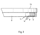
- FIG. 3 shows an enlarged detail from FIGS. 1 and 2.
- Each Disc 3, 4 has a radially arranged guide 17 for the Core drive 8, angular gear 8 'and mandrel 14 existing Rewinder 5, which by means of a drive, not shown, the can be pneumatic, hydraulic or electric motor, on the one hand radial can be pressed against the backup roller and on the other hand to remove a finished one Paper roll 16 or for attaching a new cardboard sleeve 9 radially after can be moved outside. Since the distance between the disks 3, 4, 3 ', 4' a certain web width is set, the mandrel 14 or else entire winding device 5 for attaching a cardboard tube 9 or Removal of a wound paper web 16 is axially displaceable his. Constructions familiar to the person skilled in the art can be used here without having to make almost any further explanations.
- the device according to the invention is used in such a way that one first winding device 5 of those involved in the winding process Disc pairs 3, 4, 3 ', 4' is equipped with a cardboard sleeve 9 that the Web starts of the paper web 15 cut to width on the cardboard sleeves 9 attached or wrapped and that then the support rollers 1, 2 and Cardboard tubes 9 by means of the associated drives at machine speed be started up.
- one not in the paper making process integrated slitter is the design speed of the Roll cutter or another one selected for the respective case Speed.
- an integrated in the paper manufacturing process Slitter in which the advantages of the invention really come into their own come, that's the web speed of papermaking.
- a third winding device 7 is a third winding device 7 and accordingly, a third working position is provided so that the attachment the third cardboard tube 9 and the removal of the first finished paper rolls can take place while the second roll is still being wound.
- the paper web 15 becomes transverse separated from the conveying direction and the new start of the path to the next Cardboard tube 9 wrapped, which of course beforehand Machine speed was accelerated. In the last position the wound paper webs 16 are braked and out of Take-up device removed, so that it is free to accommodate a new cardboard sleeve 9.
Abstract
Claims (13)
- Dispositif destiné à l'enroulement continu de bandes de papier coupées longitudinalement avec changement automatique de rouleaux à la vitesse de la machine, comportant au moins deux cylindres de soutien (1, 2) disposés séparément derrière un dispositif de découpe longitudinale, caractérisé parau moins un couple de disques (3, 4, 3', 4') par cylindre de soutien (1, 2), qui sont disposés de façon concentrique par rapport aux cylindres de soutien (1, 2), montés de façon à pouvoir pivoter indépendamment des cylindres de soutien (1, 2), et dont la distance axiale entre les disques peut être réglée en fonction de la largeur des bandes de papier (15) à enrouler,au moins deux dispositifs d'enroulement (5, 6, 7) par couple de disques (3, 4, 3', 4'), qui sont guidés dans les couples de disques (3, 4, 3', 4') de façon à pouvoir être déplacés radialement, et qui comportent chacun un entraínement de noyau (8) pour des douilles en carton (9) à insérer, ainsi que parau moins un dispositif (10) destiné à la séparation transversalement au sens du transport d'une bande de papier (15) découpée à largeur, et à l'enroulement du nouveau début de bande sur une nouvelle douille en carton (9) accélérée à la vitesse de la machine.
- Dispositif selon la revendication 1, caractérisé en ce que trois dispositifs d'enroulement (5, 6, 7) décalés de 120° les uns par rapport aux autres sont prévus par couple de disques (3, 4, 3', 4').
- Dispositif selon la revendication 1 ou 2, caractérisé en ce que les cylindres de soutien (1, 2) sont disposés à même hauteur l'un derrière l'autre dans le sens du transport des bandes de papier (15), et en ce que leurs couples de disques (3, 4, 3', 4') sont décalés les uns par rapport aux autres transversalement au sens du transport.
- Dispositif selon l'une des revendications 1 à 3, caractérisé en ce que chaque cylindre de soutien (1, 2) comporte, de préférence par couple de disques (3, 4, 3', 4'), un dispositif (10) destiné à la séparation et à l'enroulement.
- Dispositif selon l'une des revendications 1 à 4, caractérisé en ce que les cylindres de soutien (1, 2) comportent un entraínement à couple de rotation ou à traction de bande réglé.
- Dispositif selon l'une des revendications 1 à 5, caractérisé en ce que les couples de disques (3, 4, 3', 4') sont montés et guidés sur leur circonférence extérieure (11).
- Dispositif selon la revendication 6, caractérisé en ce que les couples de disques (3, 4, 3', 4') sont montés dans un bâti (12) de machine, dans lequel sont également montés les cylindres de soutien (1, 2).
- Dispositif selon la revendication 6 ou 7, caractérisé en ce que les couples de disques (3, 4, 3', 4') comportent un entraínement (13) qui leur est propre afin de pivoter les dispositifs d'enroulement (5, 6, 7) dans différentes positions.
- Dispositif selon l'une des revendications 1 à 8, caractérisé en ce que les dispositifs d'enroulement (5, 6, 7) peuvent être appliqués radialement vers l'intérieur contre les cylindres de soutien (1, 2).
- Dispositif selon l'une des revendications 1 à 9, caractérisé en ce que les dispositifs d'enroulement (5, 6, 7) comportent des mandrins (14) pour l'emboítement des douilles en carton (9).
- Procédé destiné à l'enroulement continu de bandes de papier (15) coupées longitudinalement avec changement automatique de rouleaux à la vitesse de la machine au moyen d'un dispositif selon l'une quelconque des revendications 1 à 10, caractérisé en ce qu'un premier dispositif d'enroulement (5) des couples de disques (3, 4, 3', 4') participant au processus d'enroulement est équipé d'une douille en carton (9), que les débuts des bandes de papier (15) découpées à largeur sont fixés ou enroulés sur les douilles en carton (9), que les cylindres de soutien (1, 2) et les douilles en carton (9) sont accélérés à la vitesse de la machine, que les disques (3, 4, 3', 4') sont pivotés dans la position suivante pendant le processus d'enroulement, qu'un deuxième dispositif d'enroulement (6) est équipé d'une douille en carton (9), que les douilles en carton (9) sont accélérées à la vitesse de la machine, que, lorsque le diamètre souhaité du rouleau est atteint, la bande de papier (15) est découpée transversalement au sens du transport et le nouveau début de bande est enroulé sur la deuxième douille en carton (9), que les couples de disques (3, 4, 3', 4') sont pivotés dans la position suivante pendant le processus d'enroulement, et que la bande de papier (16) enroulée est freinée, prélevée du premier dispositif d'enroulement (5), et que ce dernier est équipé d'une nouvelle douille en carton (9).
- Procédé selon la revendication 11, mais avec la précision que, dans le cas d'un dispositif comportant trois dispositifs d'enroulement (5, 6, 7) par couples de disques (3, 4, 3', 4'), ces derniers sont pivotés successivement dans trois positions décalées de 120° les unes par rapport aux autres, la première position servant à la mise en place d'une nouvelle douille en carton (9), la deuxième position à l'enroulement de la bande de papier (15), et la troisième au freinage et au prélèvement de la bande de papier (16) enroulée.
- Procédé selon la revendication 11 ou 12, caractérisé en ce que le changement de position de tous les couples de disques (3, 4, 3', 4') participants, et notamment le début d'enroulement sur une nouvelle douille en carton (9), sont effectués simultanément sur les différents cylindres de soutien (1, 2).
Applications Claiming Priority (3)
| Application Number | Priority Date | Filing Date | Title |
|---|---|---|---|
| DE19609802A DE19609802A1 (de) | 1996-03-13 | 1996-03-13 | Vorrichtung zur kontinuierlichen Aufrollung von längsgeschnittenen Papierbahnen mit automatischem Rollenwechsel bei Maschinengeschwindigkeit |
| DE19609802 | 1996-03-13 | ||
| PCT/EP1997/001271 WO1997033821A1 (fr) | 1996-03-13 | 1997-03-13 | Dispositif d'enroulement continu de bandes de papier coupees longitudinalement avec changement automatique des rouleaux a vitesse de la machine |
Publications (2)
| Publication Number | Publication Date |
|---|---|
| EP0886620A1 EP0886620A1 (fr) | 1998-12-30 |
| EP0886620B1 true EP0886620B1 (fr) | 2000-01-19 |
Family
ID=7788125
Family Applications (1)
| Application Number | Title | Priority Date | Filing Date |
|---|---|---|---|
| EP97907097A Expired - Lifetime EP0886620B1 (fr) | 1996-03-13 | 1997-03-13 | Dispositif d'enroulement continu de bandes de papier coupees longitudinalement avec changement automatique des rouleaux a vitesse de la machine |
Country Status (4)
| Country | Link |
|---|---|
| US (1) | US6406417B1 (fr) |
| EP (1) | EP0886620B1 (fr) |
| DE (2) | DE19609802A1 (fr) |
| WO (1) | WO1997033821A1 (fr) |
Families Citing this family (4)
| Publication number | Priority date | Publication date | Assignee | Title |
|---|---|---|---|---|
| US6709549B2 (en) * | 2001-03-29 | 2004-03-23 | Metso Paper Karlstad Ab | Multi-reel apparatus in a paper machine |
| ITFI20030118A1 (it) * | 2003-04-28 | 2004-10-29 | Fabio Perini | Dispositivo e metodo per provocare lo strappo di nastri cartacei in macchine ribobinatrici |
| DE102009001171A1 (de) * | 2009-02-26 | 2010-09-02 | Voith Patent Gmbh | Anordnung von Rollenschneideinrichtung und Verfahren zum Betreiben einer Anordnung von Rollenschneideinrichtung |
| CH705226A2 (de) * | 2011-07-05 | 2013-01-15 | Swiss Winding Inventing Ag | Wickler. |
Family Cites Families (19)
| Publication number | Priority date | Publication date | Assignee | Title |
|---|---|---|---|---|
| US2201233A (en) | 1937-09-10 | 1940-05-21 | Cameron Machine Co | Means for controlling the power drive in a winding or other machine |
| US2200000A (en) | 1937-09-10 | 1940-05-07 | Cameron Machine Co | Art of winding flexible material |
| DE1091856B (de) * | 1957-12-18 | 1960-10-27 | Jagenberg Werke Ag | Vorrichtung zum Laengsschneiden und Aufrollen unmittelbar aus der Papiermaschine kommender Papierbahnen |
| DE1474243B1 (de) * | 1964-12-24 | 1969-12-18 | Goebel Gmbh Maschf | Maschine zum ununterbrochenen Aufwickeln einer laengsgeschnittenen Bahn |
| US3433429A (en) * | 1967-04-10 | 1969-03-18 | Midland Ross Corp | Film winding apparatus |
| DE1952205C3 (de) * | 1968-10-17 | 1973-10-31 | Inta-Roto, Inc., Richmond, Va. (V.St.A.) | Verfahren zum selbsttätigen konti nuierhchen Aufwickeln endlos anfallen den bahnförmigen Gutes, insbesondere aus mehreren nebeneinanderlaufenden Teil bahnen bestehenden Gutes, und Vorrichtung zur Durchfuhrung desselben |
| US3599888A (en) | 1969-09-08 | 1971-08-17 | Inta Roto Inc | Method of and means for severing web strip material upon completion of winding a roll and initiating winding of a new roll |
| DE7012648U (de) | 1970-04-07 | 1970-08-27 | Rotomec Spa | Wickelvorrichtung. |
| FR2098606A5 (fr) | 1970-07-16 | 1972-03-10 | Riegger Paul | |
| FI811789L (fi) * | 1980-07-18 | 1982-01-19 | Jagenberg Werke Ag | Anordning foer separat upplindning av laengsgaoende banor |
| DE8019261U1 (de) | 1980-07-18 | 1982-01-21 | Jagenberg-Werke AG, 4000 Düsseldorf | Vorrichtung zum getrennten aufwickeln laengsgeteilter bahnen |
| DE3418741C2 (de) | 1984-05-19 | 1986-06-19 | Erwin Kampf Gmbh & Co Maschinenfabrik, 5276 Wiehl | Schneid- und Wickelmaschine |
| DE3645252C2 (de) * | 1986-04-28 | 1995-02-09 | Windmoeller & Hoelscher | Vorrichtung zum Wickeln von mehreren durch Längsschneiden einer breiten Materialbahn gebildeten schmalen Materialbahnen zu Vorratsrollen |
| DE3636685C2 (de) | 1986-04-28 | 1994-04-07 | Windmoeller & Hoelscher | Vorrichtung zum Wickeln von mehreren durch Längsschneiden einer breiten Materialbahn gebildeten schmalen Materialbahnen zu Vorratsrollen |
| IT1189496B (it) * | 1986-05-09 | 1988-02-04 | Meccanica Comasca Srl | Taglierina ribobinatrice per nastri adesivi e non adesivi avente almento quattro gruppi distinti di riavvolgimento |
| US5217177A (en) * | 1989-11-02 | 1993-06-08 | Ghezzi & Annoni S.P.A. | Machine with continuous operating cycle for the packaging in rolls of various strip-shaped materials by means of a plurality of simultaneous longitudinal cuts of a wide strip of material fed by a roller |
| DE4200478A1 (de) | 1991-10-24 | 1993-04-29 | Windmoeller & Hoelscher | Vorrichtung zum aufwickeln von materialbahnen auf wickelwellen |
| DE4232363C2 (de) * | 1992-09-26 | 1995-11-30 | Kloeckner Er We Pa Gmbh | Vorrichtung zum kontinuierlichen Wickeln von Materialbahnen |
| DE9413238U1 (de) * | 1994-08-17 | 1994-10-13 | Reinhold Klaus | Vorrichtung zum Aufwickeln von Materialbahnen mit einer Schneid- und Transportwalze |
-
1996
- 1996-03-13 DE DE19609802A patent/DE19609802A1/de not_active Withdrawn
-
1997
- 1997-03-13 US US09/101,704 patent/US6406417B1/en not_active Expired - Fee Related
- 1997-03-13 WO PCT/EP1997/001271 patent/WO1997033821A1/fr active IP Right Grant
- 1997-03-13 EP EP97907097A patent/EP0886620B1/fr not_active Expired - Lifetime
- 1997-03-13 DE DE59701038T patent/DE59701038D1/de not_active Expired - Lifetime
Also Published As
| Publication number | Publication date |
|---|---|
| US6406417B1 (en) | 2002-06-18 |
| DE19609802A1 (de) | 1997-09-18 |
| EP0886620A1 (fr) | 1998-12-30 |
| DE59701038D1 (de) | 2000-02-24 |
| WO1997033821A1 (fr) | 1997-09-18 |
Similar Documents
| Publication | Publication Date | Title |
|---|---|---|
| EP0145029B1 (fr) | Dispositif d'enroulement ou de déroulement à plusieurs arbres en cascade | |
| DE10035894B4 (de) | Wickeleinrichtung für Bandmaterial | |
| EP0744365B1 (fr) | Méthode pour changer le rouleau dans une machine à enrouler et machine à enrouler pour l'application de cette méthode | |
| DE4401804A1 (de) | Verfahren zum Aufwickeln einer laufenden Bahn sowie Wickelmaschine zum Durchführen des Verfahrens | |
| EP2223876B1 (fr) | Agencement de bobineuses-refendeuses et procédé de fonctionnement d'un agencement de bobineuses-refendeuses | |
| EP0886620B1 (fr) | Dispositif d'enroulement continu de bandes de papier coupees longitudinalement avec changement automatique des rouleaux a vitesse de la machine | |
| DE60200291T2 (de) | Umwickelmaschine mit Flanken zum Tragen von sich entlang einer geschlossenen Bahn bewegenden greifenden Zentrierdornen | |
| EP2184243B1 (fr) | Procédé destiné à enrouler des bandes de matériau et dispositif destiné à l'exécution du procédé | |
| EP1657194B1 (fr) | Dispositif d'enroulage de bobines et procédé pour l'enroulement de bobines | |
| EP1179630B1 (fr) | Procédé et dispositif pour la production de rouleaux de papier | |
| EP2088106B1 (fr) | Dispositif d'enroulement pour une une bande de matériau | |
| EP1657193B1 (fr) | Dispositif d'enroulage de bobines et procédé pour l'enroulement de bobines | |
| EP2082982B1 (fr) | Dispositif d'enroulement | |
| DE202006020888U1 (de) | Vorrichtung zum Aufwickeln von zumindest zwei Materialbahnen | |
| EP1842815A1 (fr) | Installation de production de papier | |
| DE102019111475B4 (de) | Abrollstation | |
| EP0896940A1 (fr) | Dispositif de bobinage, notamment dans une bobineuse-refendeuse | |
| EP1652803B1 (fr) | Procédé d'enroulement | |
| EP3368455B1 (fr) | Enrouleuse pour matériaux en forme de bande et procédé d'enroulement d'un matériau en forme de bande sur des mandrins | |
| EP0873940B1 (fr) | Machine de coupe de rouleaux avec dispositif d'emballage | |
| DE19720174B4 (de) | Kalander | |
| EP1038814B1 (fr) | Système d'enroulage pour des bandes d'une composition duroplastique | |
| EP1291308B1 (fr) | Dispositif pour enrouler des bandes de matériau en rouleaux | |
| DE60015144T2 (de) | Verfahren zum kontinuierlichen aufwickeln von papier und wickler | |
| DE10048327B4 (de) | Verfahren zum Wickeln einer Papierbahn und Wickelvorrichtung für Papierbahn |
Legal Events
| Date | Code | Title | Description |
|---|---|---|---|
| PUAI | Public reference made under article 153(3) epc to a published international application that has entered the european phase |
Free format text: ORIGINAL CODE: 0009012 |
|
| 17P | Request for examination filed |
Effective date: 19980528 |
|
| AK | Designated contracting states |
Kind code of ref document: A1 Designated state(s): DE FI FR GB |
|
| RAP1 | Party data changed (applicant data changed or rights of an application transferred) |
Owner name: VOITH SULZER PAPIERTECHNIK PATENT GMBH |
|
| GRAG | Despatch of communication of intention to grant |
Free format text: ORIGINAL CODE: EPIDOS AGRA |
|
| GRAG | Despatch of communication of intention to grant |
Free format text: ORIGINAL CODE: EPIDOS AGRA |
|
| GRAH | Despatch of communication of intention to grant a patent |
Free format text: ORIGINAL CODE: EPIDOS IGRA |
|
| 17Q | First examination report despatched |
Effective date: 19990607 |
|
| GRAH | Despatch of communication of intention to grant a patent |
Free format text: ORIGINAL CODE: EPIDOS IGRA |
|
| GRAA | (expected) grant |
Free format text: ORIGINAL CODE: 0009210 |
|
| AK | Designated contracting states |
Kind code of ref document: B1 Designated state(s): DE FI FR GB |
|
| GBT | Gb: translation of ep patent filed (gb section 77(6)(a)/1977) |
Effective date: 20000119 |
|
| REF | Corresponds to: |
Ref document number: 59701038 Country of ref document: DE Date of ref document: 20000224 |
|
| ET | Fr: translation filed | ||
| PLBE | No opposition filed within time limit |
Free format text: ORIGINAL CODE: 0009261 |
|
| STAA | Information on the status of an ep patent application or granted ep patent |
Free format text: STATUS: NO OPPOSITION FILED WITHIN TIME LIMIT |
|
| 26N | No opposition filed | ||
| REG | Reference to a national code |
Ref country code: GB Ref legal event code: IF02 |
|
| PGFP | Annual fee paid to national office [announced via postgrant information from national office to epo] |
Ref country code: GB Payment date: 20030224 Year of fee payment: 7 |
|
| PGFP | Annual fee paid to national office [announced via postgrant information from national office to epo] |
Ref country code: FR Payment date: 20030320 Year of fee payment: 7 |
|
| PG25 | Lapsed in a contracting state [announced via postgrant information from national office to epo] |
Ref country code: GB Free format text: LAPSE BECAUSE OF NON-PAYMENT OF DUE FEES Effective date: 20040313 |
|
| GBPC | Gb: european patent ceased through non-payment of renewal fee |
Effective date: 20040313 |
|
| PG25 | Lapsed in a contracting state [announced via postgrant information from national office to epo] |
Ref country code: FR Free format text: LAPSE BECAUSE OF NON-PAYMENT OF DUE FEES Effective date: 20041130 |
|
| REG | Reference to a national code |
Ref country code: FR Ref legal event code: ST |
|
| PGFP | Annual fee paid to national office [announced via postgrant information from national office to epo] |
Ref country code: FI Payment date: 20050311 Year of fee payment: 9 |
|
| PG25 | Lapsed in a contracting state [announced via postgrant information from national office to epo] |
Ref country code: FI Free format text: LAPSE BECAUSE OF NON-PAYMENT OF DUE FEES Effective date: 20060313 |
|
| PGFP | Annual fee paid to national office [announced via postgrant information from national office to epo] |
Ref country code: DE Payment date: 20100324 Year of fee payment: 14 |
|
| PG25 | Lapsed in a contracting state [announced via postgrant information from national office to epo] |
Ref country code: DE Free format text: LAPSE BECAUSE OF NON-PAYMENT OF DUE FEES Effective date: 20111001 |
|
| REG | Reference to a national code |
Ref country code: DE Ref legal event code: R119 Ref document number: 59701038 Country of ref document: DE Effective date: 20111001 |