EP0885851A2 - Verfahren und Vorrichtung zum Biegen von Glasscheiben - Google Patents
Verfahren und Vorrichtung zum Biegen von Glasscheiben Download PDFInfo
- Publication number
- EP0885851A2 EP0885851A2 EP98110666A EP98110666A EP0885851A2 EP 0885851 A2 EP0885851 A2 EP 0885851A2 EP 98110666 A EP98110666 A EP 98110666A EP 98110666 A EP98110666 A EP 98110666A EP 0885851 A2 EP0885851 A2 EP 0885851A2
- Authority
- EP
- European Patent Office
- Prior art keywords
- sheet
- rail
- shaping
- auxiliary
- shaping surface
- Prior art date
- Legal status (The legal status is an assumption and is not a legal conclusion. Google has not performed a legal analysis and makes no representation as to the accuracy of the status listed.)
- Granted
Links
Images


Classifications
-
- C—CHEMISTRY; METALLURGY
- C03—GLASS; MINERAL OR SLAG WOOL
- C03B—MANUFACTURE, SHAPING, OR SUPPLEMENTARY PROCESSES
- C03B23/00—Re-forming shaped glass
- C03B23/02—Re-forming glass sheets
- C03B23/023—Re-forming glass sheets by bending
- C03B23/025—Re-forming glass sheets by bending by gravity
- C03B23/0252—Re-forming glass sheets by bending by gravity by gravity only, e.g. sagging
-
- C—CHEMISTRY; METALLURGY
- C03—GLASS; MINERAL OR SLAG WOOL
- C03B—MANUFACTURE, SHAPING, OR SUPPLEMENTARY PROCESSES
- C03B23/00—Re-forming shaped glass
- C03B23/02—Re-forming glass sheets
- C03B23/023—Re-forming glass sheets by bending
- C03B23/025—Re-forming glass sheets by bending by gravity
- C03B23/027—Re-forming glass sheets by bending by gravity with moulds having at least two upward pivotable mould sections
Definitions
- This invention relates to sag bending of glass sheets on bending molds and, in particular, to an apparatus and method for controlling the sag bending along selected portions of the glass sheets while moving the sheets on bending molds through a heating lehr.
- a glass sheet is supported on a skeletal bending mold.
- the shaping rail of the mold has a shape and configuration similar to that of the shaped glass sheet at a location slightly inboard of its peripheral edge.
- the bending molds are then conveyed in succession through a heating lehr where the glass sheet is heated to its deformation temperature such that it begins to sag by gravity until the glass sheet conforms to the configuration of the shaping rail.
- the mold is conveyed through an annealing zone where the glass sheet is cooled in a controlled manner from its deformation temperature through its annealing range to anneal the glass sheet.
- This gravity sag bending technique has been used to simultaneously shape two glass sheets, or doublets, which sheets are subsequently laminated together to form an automobile windshield.
- Patent 5,167,689 to Weber controls bending at the corners of glass sheets supported on an outline mold by sag bending the sheets to a preliminarily curved configuration and subsequently lifting selected peripheral portions of the sheet off the curved shaping rails with additional shaping rails having the final desired elevational configuration. This arrangement reduces reverse bending at the corners of the glass sheets but does not address the problem of excessive sag of the glass near the shaping rails.
- the present invention provides an apparatus and method for a shaping sheet including a support frame and a shaping rail supported on the frame.
- the shaping rail has a sheet shaping surface that conforms in elevation and outline to a final desired shape of a marginal edge of a glass sheet to be shaped.
- An auxiliary rail having a sheet shaping surface which generally corresponds to a preliminary shape of a selected marginal edge portion of the sheet is positioned along a section of the shaping rail having a sheet shaping surface portion which generally corresponds to the final desired shape of the selected marginal edge portion of the sheet.
- the auxiliary rail is mounted for movement relative to the shaping rail section from a first position, wherein portions of the sheet shaping surface of the auxiliary rail are above the sheet shaping surface portion of the shaping rail section, and a second position wherein the sheet shaping surface of the auxiliary rail is positioned below the sheet shaping surface portion of the shaping rail section.
- the auxiliary rail When the auxiliary rail is in its first position, it is capable of supporting the selected marginal edge portion of the sheet above the shaping rail section and preliminarily shaping the sheet.
- the sheet shaping surface portion of the shaping rail section is capable of supporting and shaping the selected marginal edge portion of the sheet to the final desired shape.
- Figure 1 is a perspective cutaway view of a heating lehr showing glass sheets supported on an outline ring mold incorporating the present invention, with portions removed for clarity.
- FIG 2 is an enlarged perspective view of a pivoting wing section of the ring mold illustrated in Figure 1, with portions removed for clarity.
- Figure 3 is an end view of the pivoting wing section of the ring mold illustrated in Figure 1 showing an auxiliary rail in a raised and lowered position, with portions removed for clarity.
- Figures 4, 5 and 6 are schematic sectional views of the pivoting section of the ring mold illustrated in Figure 1 taken along line A-A at different stages during a glass sheet sag bending operation, with portions removed for clarity.
- Figure 7 is an end view of an alternate embodiment of the ring mold of the present invention, with portions removed for clarity, showing an auxiliary rail in a raised and lowered position.
- Figure 8 is a side view of another embodiment of the ring mold of the present invention, with portions removed for clarity, showing an auxiliary rail in a raised and lowered position.
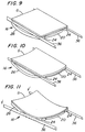
- Figures 9, 10 and 11 are schematic perspective views generally corresponding to Figures 4, 5 and 6, respectively, showing the shaping sequence of a sheet supported on the outline rail of the present invention, with portions removed for clarity.
- the invention as discussed herein is presented in combination with a conventional stop-and-go type heating lehr, wherein the glass sheets are supported on shaping rails within separate heating chambers that are sequentially conveyed through the lehr to heat and shape the glass sheets, in a manner well known in the art. It should be appreciated that the present invention may be incorporated into the sag bending operation of glass sheets using other types of heating lehrs, e.g. conventional tunnel-type lehrs.
- one or more glass sheets G are positioned on a carrying frame 10 at a loading station (not shown) and conveyed through a heating lehr 12, where they are heated to their heat-softening temperature and allowed to sag by gravity to a desired shaped configuration.
- the sheets G and frame 10 are conveyed through annealing and cooling zones of the lehr 12 to minimize stresses in the glass and set the glass shape.
- a conveyor comprised of a plurality of stub rolls 14 disposed in transversely opposing, longitudinally spaced relation extend the entire length of the lehr 12 and defines a path of movement of frame 10 along a longitudinal reference line through the lehr.
- Each stub roll 14 is mounted on a shaft that extends through a side wall of the lehr 12 and is connected to a conveyor drive means (not shown).
- the conveyor may be divided into a number of sections, each driven from its own drive means, or the conveyor sections may be driven from a common drive through clutches, in any manner well known in the art.
- the frame 10 illustrated in Figure 1 includes a ring mold 16, similar to the mold disclosed in U.S. Patent 4,626,267 to Reese and U.S. Patent 4,804,397 to Stas et al., which teachings are herein incorporated by reference, having a sheet shaping surface 18 that conforms in elevation and outline to a final desired shape of the marginal edge of the glass sheets G to be shaped.
- Frame 10 may include other insulating structures (not shown) which enclose the frame 10 and isolate it from adjacent frames.
- mold 16 is an articulating mold with pivoting end sections; however, it should be appreciated that the present invention may be used in combination with a non-articulating ring mold.
- the mold 16 is provided with opposed, spaced-apart central rails 20 (only one shown in Figure 1) and two pivoting end sections 22, each of which includes side rails 24 and an end rail 26. Each end section 22 is supported by an outrigger 28 positioned below the corresponding rails 24 and 26. The outrigger 28 extends outward of the end sections 22 towards a pivot on post 30 and is attached to a weighted lever arm 32. As the glass sheets G supported on ring mold 16 are heated, the lever arm 32 moves downward under the force of gravity against the lessening opposing force of the glass sheets G as they become heat softened to pivot the end sections 22 upward to a closed position as shown in Figure 1. In this closed position, rails 20, 24 and 26 form shaping surface 18 and the glass sheets G sag by gravity into contact and are shaped by surface 18 slightly inboard of their periphery.
- end section 22 of mold 16 further includes an auxiliary rail 34 which extends along and is positioned adjacent to end rail section 26 of end section 22.
- Auxiliary rail 34 is supported on frame 10 to move between a raised position wherein the upper sheet shaping surface 36 of auxiliary rail 34 is generally positioned above the upper sheet shaping surface 38 of adjacent rail 26 as illustrated in Figures 1, 2 and 3, to support and preliminarily shape a marginal edge portion 40 of the glass sheets G, and a lowered position wherein surface 36 of auxiliary rail 34 is positioned below surface 38 of adjacent end rail 26 as illustrated by phantom lines 42 in Figure 3 such that rail 26 can support and shape marginal edge portion 40 to its final desired configuration during a portion of the sag bending process.
- the elevational profile of shaping surface 36 is configured to have a curvature which is less than that of surface 38 of adjacent rail 26 so that as long as marginal edge portion 40 is supported on auxiliary rail 34, it cannot sag to its final configuration.
- shaping surface 36 of auxiliary rail 34 has a straight profile, i.e. there is no vertical curvature along its length and is positioned so that it is aligned slightly above the highest points of adjacent rail 26.
- Auxiliary rail 34 may be moved from its raised position to its lowered position either by gravity or a mechanical or electro-mechanical device.
- Figures 2 and 3 illustrate one embodiment of a gravity-type arrangement. More specifically, end 44 of rail 34 is mounted to pivot about post 45.
- a bracket 46 which includes a ledge 48, is pivotally secured to outrigger 28 or a guide 50 of pivoting section 22. When in its raised position, rail 34 is supported at one end by post 45 and its opposing end is seated on ledge 48.
- bracket 46 is pivoted away from rail 34 causing the rail 34 to move off ledge 48 and slides downward, as shown by phantom lines 42 in Figure 3, pivoting about post 45.
- Guide 50 maintains auxiliary rail 34's position generally along adjacent rail 26.
- guide 50 includes a plate 52 with a slot 54 through which rail 34 extends and slides along.
- bracket 46 occurs when end section 22 of mold 16 pivots upward a predetermined amount. More particularly, referring to Figures 4 through 6, arm 56 extends from bracket 46 and includes a pivoting rod 58 that extends through a portion of frame 10. Stop 60 is secured to rod 58 such that when end section 22 of mold 16 is pivoted downward to an opened position, the stop 60 is spaced from frame 10, as illustrated in Figure 4. As the glass sheets G supported on rails 20, 24 and 34 are heated and softened, pivoting end section 22 begins to rotate upward, as indicated by arrow 62 in Figure 5, to slowly obtain the final desired elevational contour of the sheet. Bracket 46 moves with section 22 as it pivots and continues to hold rail 34 in its raised position as shown in Figure 5.
- bracket 46 is prevented from maintaining its orientation relative to rail 34 and is forced to pivot, as indicated by arrow 64, which results in rail 34 falling off ledge 48 and dropping to its lowered position, as illustrated in Figure 6 and depositing the sheet onto end rail 26.
- bracket 46 is positioned at one end of rail 34; it should be appreciated that it may be positioned at any other location along rail 34, for example, at its center. It should be further appreciated that other types of devices may be used to move rail 34 from its raised position to its lowered position.
- bracket 46 may be replaced with a linear actuator, such as an electric motor, ball screw, electric motor, or the like, to raise and lower one end of rail 34.
- the rail 34 may be vertically reciprocated between its raised and lowered positions. More specifically, referring to Figure 7, opposing ends of rail 34 may be supported by linear actuators 66, as discussed above, to move both ends of rail 34 upward to its raised position and downward to its lowered position, as indicated by phantom lines 68. These types of actuators may be linked to a controller (not shown) which controls the raising and lowering of rail 34 during the gravity sag bending operation.
- rail 34 may be moved from its raised to lowered position by a pivoting action. More specifically, referring to Figure 8, rail 34 may include additional sections 70 (only one shown in Figure 8) which are pivotally mounted to frame 10 so that rather than simply dropping from its raised to lowered position, rail 34 and additional sections 70 rotate away from adjacent rail 26, as indicated by phantom lines 72. The rail 34 and section 70 may be raised and lowered in a manner as previously discussed.
- a sag bending temperature of between about 1060 to 1250°F (571 to 677°C)
- the ring mold 16 of the present invention shapes the sheets first in one direction to preliminarily shape the sheets generally in the longitudinal direction and subsequently in a second direction to impart a transverse curvature and shape the sheets to their final desired configuration. More specifically, end sections 22 of the ring mold 16 are pivoted downward and auxiliary rails 34 (one on each section 22) are moved to their raised position, as shown in Figures 4 and 9, either manually or by an automatic rail positioning arrangement. Glass sheets G (only one shown in Figures 4-6 and 9-11) are positioned on the ring mold 16 and supported on rails 34 and end sections 74 of side rails 20. As the sheets are heated, they soften and sag by gravity.
- Marginal edge portions 76 along the longitudinal sides of the glass sheets G sag into contact with and are shaped by center rails 20 and rails 24 in end section 22 as weighted arms 32 (shown only in Figure 1) pivot each end section 22 upward, as shown in Figures 5 and 10.
- the marginal edge portions 40 of the glass sheets G are supported on auxiliary rail 34, which is initially positioned above rail 26 of end section 22 and remain undeformed. As a result, the glass sheets G initially deform to assume their longitudinal curvature, i.e. a generally cylindrical curvature from one end section 22 to the other. During this preliminary shaping, there may be some transverse sag bending of the glass, i.e.
- each auxiliary rail 34 is configured to limit sag bending of marginal edge portions 40 of sheets G immediately inboard of auxiliary rails 34, as shown in Figures 5 and 10.
- rails 34 are lowered, depositing marginal edge portions 40 onto rails 26 of end sections 22, as shown in Figures 6 and 11.
- the glass sheets G continue to sag by gravity for the time required by the marginal edge portions 40 to contact shaping surfaces 38 of rail 26 and complete the transverse shaping of the glass G in pivoting sections 22.
- the frame 10 and shaped glass sheet G are conveyed through the annealing and cooling sections (not shown) of lehr 12 where the glass sheets G are controllably cooled.
- the shaped sheets G are subsequently removed from the mold 16 for further processing.
- additional sheet shaping arrangements may be used to further deform the sheets. More specifically, partial or full surface press faces may contact the upper and/or lower major surfaces of the glass sheets G to contact and shape selected portions of the glass to a desired configuration, for example, as disclosed in U.S. Patent 4,804,397.
- additional pressing molds are used in combination with an articulating ring mold as disclosed herein to shape the glass, it is desirable to incorporate a locking device into the pivoting end sections 22 of mold 16 so that the end sections 22 do not rotate downward when the glass G is contacted and pressed to shape, as disclosed in U.S. Patent 4,804,397.
- auxiliary rail 34 is a straight rail with a straight sheet shaping surface 36 positioned outboard of rail 26 and is moved vertically from its raised to lowered position. It is contemplated that the position and shape of the rail may be modified. For example, auxiliary rail 34 may extend only along a portion of rail 26 so that it does not support the entire marginal edge 40 of the sheets G. In addition, auxiliary rail 34 may be positioned inboard of rail 26 rather than outboard.
- auxiliary rail 34 be positioned above sheet shaping surface 38 of rail 26 when rail 34 is at its raised position, it is contemplated that surface 36 may be positioned above only a portion of surface 38 so that marginal edge portion 40 of glass sheets G is supported on and preliminarily shaped by both the auxiliary rail 34 and rail 26.
- Auxiliary rail 34 may also be curved horizontally to conform to the horizontal contour of adjacent rail 26.
- the elevational contour of sheet shaping surface 36 of auxiliary rail 34 be straight in order to control sag bending in the side portions of the glass sheets G, especially in the vicinity of the marginal edge portions 40.
- the surface 36 may be curved, provided that its curvature is less than the final desired contour of surface 38 of adjacent rail 26, i.e. it has a larger radius of curvature.
- surface 36 of auxiliary rail 34 may have a radius of curvature on the order of about 177 inches (about 450 cm), while surface 38 of adjacent rail 26 has a radius of curvature on the order of about 89 inches (about 225 cm).
- auxiliary rail 34 can preliminarily shape marginal edge portion 40 and allow some preliminary sag bending in the vicinity of marginal edge portions 40 during the majority of the sag bending operation and surface 38 of adjacent rail 26 can shape marginal edge portion 40 and the remaining portions of the glass sheets G to their final desired shape during the latter portion of the sag bending operation.
- the present invention controls excessive gravity sag bending in glass sheets by limiting the amount of glass sag at selected areas of the glass sheets during a portion of the sag bending operation.
- the glass sheets are preliminarily formed about one axis and subsequently formed about a second axis. This is accomplished by allowing the opposing longitudinally extending marginal edge portions 76 of the glass sheets G to sag into contact with opposing rails 20 and 24 while supporting the transversely extending marginal edge portions 40 of the glass sheets G on auxiliary rails 34. As a result, the sheets G assume their general longitudinal curvature.
- Rails 34 are thereafter lowered to allow edge portions 40 to be supported by and sag into contact with rails 26 of end sections 22 facilitate sag bending of the glass sheets in the transverse direction, especially in the vicinity between rails 24 of end sections 22, and complete the shaping of the glass.
- the contoured shape of the glass in the pivoting sections 22 is controlled and excess sag bending is minimized.
- reducing the excessive sag bending by controlling the rate and manner in which the glass is shaped will also reduce distortion in the glass sheet due to undesired reverse bending of the sheet, especially at its corners.
Landscapes
- Chemical & Material Sciences (AREA)
- Engineering & Computer Science (AREA)
- Materials Engineering (AREA)
- Organic Chemistry (AREA)
- Re-Forming, After-Treatment, Cutting And Transporting Of Glass Products (AREA)
Applications Claiming Priority (2)
| Application Number | Priority Date | Filing Date | Title |
|---|---|---|---|
| US08/876,872 US6076373A (en) | 1997-06-16 | 1997-06-16 | Apparatus and method for bending glass sheets |
| US876872 | 1997-06-16 |
Publications (3)
| Publication Number | Publication Date |
|---|---|
| EP0885851A2 true EP0885851A2 (de) | 1998-12-23 |
| EP0885851A3 EP0885851A3 (de) | 1999-03-10 |
| EP0885851B1 EP0885851B1 (de) | 2006-12-13 |
Family
ID=25368747
Family Applications (1)
| Application Number | Title | Priority Date | Filing Date |
|---|---|---|---|
| EP98110666A Revoked EP0885851B1 (de) | 1997-06-16 | 1998-06-10 | Verfahren und Vorrichtung zum Biegen von Glasscheiben |
Country Status (6)
| Country | Link |
|---|---|
| US (1) | US6076373A (de) |
| EP (1) | EP0885851B1 (de) |
| JP (1) | JP2889877B2 (de) |
| CA (1) | CA2235447C (de) |
| DE (1) | DE69836603T2 (de) |
| ES (1) | ES2277367T3 (de) |
Cited By (10)
| Publication number | Priority date | Publication date | Assignee | Title |
|---|---|---|---|---|
| JP2002308635A (ja) * | 2001-04-10 | 2002-10-23 | Asahi Glass Co Ltd | ガラス板曲げ成形装置および成形方法 |
| WO2008068526A1 (en) * | 2006-12-04 | 2008-06-12 | Pilkington Group Limited | Gravity bending glass sheets |
| NL2000699C2 (nl) * | 2007-06-12 | 2008-12-15 | Univ Delft Tech | Werkwijze en inrichting voor het vormen van een dubbelgekromd paneel uit een vlak paneel. |
| WO2012028630A1 (fr) | 2010-09-03 | 2012-03-08 | Agc Glass Europe | Procédé d'élaboration de formes de vitrages |
| US8459061B2 (en) | 2008-06-02 | 2013-06-11 | Pilkington Group Limited | Gravity bending glass sheets |
| US8459060B2 (en) | 2006-12-04 | 2013-06-11 | Pilkington Group Limited | Gravity bending glass sheets |
| DE102012107968A1 (de) * | 2012-08-29 | 2014-03-06 | Schott Ag | Glasfertigungswerkzeug und Verfahren zum Umformen eines flächigen und plastisch verformbaren Werkstückes |
| US8677784B2 (en) | 2007-12-11 | 2014-03-25 | Pilkington Group Limited | Gravity bending glass sheets |
| US9061934B2 (en) | 2011-10-10 | 2015-06-23 | Corning Incorporated | Apparatus and method for tight bending thin glass sheets |
| WO2019077278A1 (fr) | 2017-10-19 | 2019-04-25 | Saint-Gobain Glass France | Bombage de verre par gravite en presence d'un contre-squelette radiatif |
Families Citing this family (21)
| Publication number | Priority date | Publication date | Assignee | Title |
|---|---|---|---|---|
| US6953758B2 (en) | 1998-05-12 | 2005-10-11 | Ppg Industries Ohio, Inc. | Limited visible transmission blue glasses |
| US6629436B1 (en) | 2000-11-03 | 2003-10-07 | Ppg Industries Ohio, Inc. | Apparatus for thermal treatment of glass and method and thermally treated glass therefrom |
| FI117354B (fi) * | 2003-06-02 | 2006-09-15 | Tamglass Ltd Oy | Menetelmä reunamuotilla taivutettavan lasilevyn taivutuspussikkuuden mittaamiseksi |
| US20050092028A1 (en) * | 2003-11-05 | 2005-05-05 | William Blanc | Light weight gravity bending ring |
| FR2894955B1 (fr) * | 2005-12-20 | 2008-05-02 | Saint Gobain | Dispositif de bombage de verre par gravite sur plusieurs formes de support a transition de forme controlee |
| JP5157225B2 (ja) * | 2007-04-06 | 2013-03-06 | セントラル硝子株式会社 | ガラス板の曲げ型および曲げ成形方法 |
| US7975509B2 (en) * | 2007-06-27 | 2011-07-12 | Pilkington North America, Inc. | Glass bending process |
| FR2942793B1 (fr) * | 2009-03-05 | 2012-03-23 | Saint Gobain | Formage d'un vitrage comprenant une ouverture |
| US8440583B2 (en) | 2010-05-27 | 2013-05-14 | Ppg Industries Ohio, Inc. | Blue glass composition |
| MX344209B (es) | 2010-12-13 | 2016-12-08 | Saint Gobain | Panel doblado. |
| EP2463247A1 (de) * | 2010-12-13 | 2012-06-13 | Saint-Gobain Glass France | Verfahren und Vorrichtung zum Biegen von Scheiben |
| EP2463248A1 (de) | 2010-12-13 | 2012-06-13 | Saint-Gobain Glass France | Verfahren und Vorrichtung zum Biegen von Scheiben |
| FR2982855B1 (fr) * | 2011-11-17 | 2013-11-08 | Saint Gobain | Bombage a froid d'un vitrage feuillete |
| US8549885B2 (en) * | 2011-11-23 | 2013-10-08 | Corning Incorporated | Process and system for precision glass sheet bending |
| US20160304384A1 (en) * | 2013-12-03 | 2016-10-20 | Nippon Sheet Glass Company, Limited | Glass plate and method for producing glass plate |
| FR3017865A1 (fr) | 2014-02-27 | 2015-08-28 | Saint Gobain | Bombage par gravite sur double-support |
| RU2677509C1 (ru) | 2015-08-18 | 2019-01-17 | Сэн-Гобэн Гласс Франс | Устройство и способ моллирования стекла с использованием вентилятора |
| PE20180789A1 (es) | 2015-09-08 | 2018-05-08 | Saint Gobain | Metodo de flexion por gravedad asistido por sobrepresion y dispositivo apropiado para el mismo |
| BR112017027456B1 (pt) | 2015-11-25 | 2022-10-18 | Saint-Gobain Glass France | Método de curvatura por gravidade auxiliado por sobrepressão, dispositivo adequado para o mesmo e uso de uma ferramenta de moldagem superior |
| EP3408233B1 (de) | 2016-01-28 | 2019-10-02 | Saint-Gobain Glass France | Überdruckunterstütztes glasbiegeverfahren und hierfür geeignete vorrichtung |
| KR102580465B1 (ko) * | 2016-11-23 | 2023-09-21 | 필킹톤 그룹 리미티드 | 유리 시트를 성형하는 방법 및 그에 사용된 벤딩 공구 |
Citations (9)
| Publication number | Priority date | Publication date | Assignee | Title |
|---|---|---|---|---|
| US2608030A (en) * | 1947-10-09 | 1952-08-26 | Libbey Owens Ford Glass Co | Mold for bending glass plates |
| US2702445A (en) * | 1951-04-20 | 1955-02-22 | Libbey Owens Ford Glass Co | Apparatus for bending sheets of glass or like materials |
| US2920423A (en) * | 1955-10-07 | 1960-01-12 | Libbey Owens Ford Glass Co | Apparatus for bending glass sheets |
| US3235350A (en) * | 1960-10-31 | 1966-02-15 | Pittsburgh Plate Glass Co | Method and apparatus for bending glass sheets |
| US4119424A (en) * | 1977-06-03 | 1978-10-10 | Ppg Industries, Inc. | Method and apparatus for shaping glass sheets on a bending mold |
| US5167689A (en) * | 1990-03-20 | 1992-12-01 | Saint-Gobain Vitrage International C/O Saint-Gobain Recherche | Process for bending glass sheets |
| EP0640569A1 (de) * | 1993-08-31 | 1995-03-01 | Saint-Gobain Vitrage | Verfahren und Vorrichtung zum Biegen von Glasscheiben |
| EP0705798A1 (de) * | 1994-10-04 | 1996-04-10 | Saint-Gobain Vitrage | Verfahren und Vorrichtung zum Biegen von Glasscheiben |
| WO1996012682A1 (en) * | 1994-10-25 | 1996-05-02 | Risto Nikander | A method and apparatus in bending and tempering of a glass sheet |
Family Cites Families (21)
| Publication number | Priority date | Publication date | Assignee | Title |
|---|---|---|---|---|
| US2452488A (en) * | 1941-12-19 | 1948-10-26 | Libbey Owens Ford Glass Co | Apparatus for bending glass |
| US2554572A (en) * | 1948-12-30 | 1951-05-29 | Libbey Owens Ford Glass Co | Shaping mold |
| US2608039A (en) * | 1949-06-13 | 1952-08-26 | Abramowski Bruno | Machine for wrapping cigarettes |
| US2695476A (en) * | 1950-12-05 | 1954-11-30 | Libbey Owens Ford Glass Co | Apparatus for shaping glass sheets |
| NL285011A (de) * | 1961-11-03 | 1900-01-01 | ||
| US3356480A (en) * | 1963-02-25 | 1967-12-05 | Pittsburgh Plate Glass Co | Method for bending glass sheets |
| GB1157090A (en) * | 1965-12-02 | 1969-07-02 | Triplex Safety Glass Co | Improvements in or relating to a method and apparatus for Bending Glass in Sheet Form |
| US4047916A (en) * | 1976-09-21 | 1977-09-13 | Ppg Industries, Inc. | Method and apparatus for bending glass sheets to double V-bends |
| DE2741965C3 (de) * | 1977-09-17 | 1980-07-24 | Vereinigte Glaswerke Gmbh, 5100 Aachen | Verfahren und Vorrichtung zum Biegen von Glasscheiben |
| JPS55158138A (en) * | 1979-05-23 | 1980-12-09 | Nissan Motor Co Ltd | Manufacture of bent glass |
| US4265650A (en) * | 1979-11-02 | 1981-05-05 | Ppg Industries, Inc. | Method of bending glass sheets in unison to complicated shapes |
| JPS6183640A (ja) * | 1984-09-26 | 1986-04-28 | Nippon Sheet Glass Co Ltd | 板ガラスのプレス成形方法及び装置 |
| US4596592A (en) * | 1985-05-02 | 1986-06-24 | Ppg Industries, Inc. | Stop members for glass sheet shaping molds |
| US4626267A (en) * | 1985-09-16 | 1986-12-02 | Ppg Industries, Inc. | Method and apparatus to reduce tip curl of a glass sheet on a bending mold |
| US4741751A (en) * | 1987-01-05 | 1988-05-03 | Ppg Industries, Inc. | Extended surface pressing mold and method of sheet shaping |
| US4804397A (en) * | 1987-12-16 | 1989-02-14 | Ppg Industries, Inc. | Partial press in gravity bending furnace and method of use |
| US4894080A (en) * | 1988-09-26 | 1990-01-16 | Ppg Industries, Inc. | In-lehr glass sheet press bending using pressurized gas |
| JPH0613223Y2 (ja) * | 1989-05-22 | 1994-04-06 | セントラル硝子株式会社 | ガラス板の曲げ型 |
| JP2727745B2 (ja) * | 1989-08-24 | 1998-03-18 | 旭硝子株式会社 | 曲げ合せガラス及び合せガラス用素板ガラスの曲げ加工方法 |
| US5049178A (en) * | 1989-09-11 | 1991-09-17 | Ppg Industries, Inc. | Partial press apparatus and method for glass sheet bending |
| US5186730A (en) * | 1990-03-20 | 1993-02-16 | Saint-Gobain Vitrage International C/O Saint-Gobain Recherche | Device having final frame which doubles a blank frame, for bending glass sheets |
-
1997
- 1997-06-16 US US08/876,872 patent/US6076373A/en not_active Expired - Lifetime
-
1998
- 1998-05-22 CA CA002235447A patent/CA2235447C/en not_active Expired - Fee Related
- 1998-06-10 ES ES98110666T patent/ES2277367T3/es not_active Expired - Lifetime
- 1998-06-10 DE DE69836603T patent/DE69836603T2/de not_active Expired - Lifetime
- 1998-06-10 EP EP98110666A patent/EP0885851B1/de not_active Revoked
- 1998-06-15 JP JP10166513A patent/JP2889877B2/ja not_active Expired - Fee Related
Patent Citations (9)
| Publication number | Priority date | Publication date | Assignee | Title |
|---|---|---|---|---|
| US2608030A (en) * | 1947-10-09 | 1952-08-26 | Libbey Owens Ford Glass Co | Mold for bending glass plates |
| US2702445A (en) * | 1951-04-20 | 1955-02-22 | Libbey Owens Ford Glass Co | Apparatus for bending sheets of glass or like materials |
| US2920423A (en) * | 1955-10-07 | 1960-01-12 | Libbey Owens Ford Glass Co | Apparatus for bending glass sheets |
| US3235350A (en) * | 1960-10-31 | 1966-02-15 | Pittsburgh Plate Glass Co | Method and apparatus for bending glass sheets |
| US4119424A (en) * | 1977-06-03 | 1978-10-10 | Ppg Industries, Inc. | Method and apparatus for shaping glass sheets on a bending mold |
| US5167689A (en) * | 1990-03-20 | 1992-12-01 | Saint-Gobain Vitrage International C/O Saint-Gobain Recherche | Process for bending glass sheets |
| EP0640569A1 (de) * | 1993-08-31 | 1995-03-01 | Saint-Gobain Vitrage | Verfahren und Vorrichtung zum Biegen von Glasscheiben |
| EP0705798A1 (de) * | 1994-10-04 | 1996-04-10 | Saint-Gobain Vitrage | Verfahren und Vorrichtung zum Biegen von Glasscheiben |
| WO1996012682A1 (en) * | 1994-10-25 | 1996-05-02 | Risto Nikander | A method and apparatus in bending and tempering of a glass sheet |
Cited By (18)
| Publication number | Priority date | Publication date | Assignee | Title |
|---|---|---|---|---|
| JP2002308635A (ja) * | 2001-04-10 | 2002-10-23 | Asahi Glass Co Ltd | ガラス板曲げ成形装置および成形方法 |
| WO2002083582A1 (fr) * | 2001-04-10 | 2002-10-24 | Asahi Glass Company, Limited | Dispositif et procede permettant de cintrer une plaque de verre |
| US6705116B2 (en) | 2001-04-10 | 2004-03-16 | Asahi Glass Company, Limited | Method and an apparatus for bending a glass sheet |
| KR100793656B1 (ko) | 2001-04-10 | 2008-01-10 | 아사히 가라스 가부시키가이샤 | 유리판의 굽힘성형방법 및 장치 |
| CZ299049B6 (cs) * | 2001-04-10 | 2008-04-09 | Asahi Glass Company, Limited | Zpusob a zarízení pro ohýbání sklenené tabule |
| US8459060B2 (en) | 2006-12-04 | 2013-06-11 | Pilkington Group Limited | Gravity bending glass sheets |
| CN101605733B (zh) * | 2006-12-04 | 2012-07-18 | 皮尔金顿集团有限公司 | 重力弯曲玻璃板 |
| US8327668B2 (en) | 2006-12-04 | 2012-12-11 | Pilkington Group Limited | Gravity bending glass sheets |
| WO2008068526A1 (en) * | 2006-12-04 | 2008-06-12 | Pilkington Group Limited | Gravity bending glass sheets |
| NL2000699C2 (nl) * | 2007-06-12 | 2008-12-15 | Univ Delft Tech | Werkwijze en inrichting voor het vormen van een dubbelgekromd paneel uit een vlak paneel. |
| WO2009002158A1 (en) * | 2007-06-12 | 2008-12-31 | Technische Universiteit Delft | A method and apparatus for forming a double-curved panel from a flat panel |
| US8677784B2 (en) | 2007-12-11 | 2014-03-25 | Pilkington Group Limited | Gravity bending glass sheets |
| US8459061B2 (en) | 2008-06-02 | 2013-06-11 | Pilkington Group Limited | Gravity bending glass sheets |
| WO2012028630A1 (fr) | 2010-09-03 | 2012-03-08 | Agc Glass Europe | Procédé d'élaboration de formes de vitrages |
| US9061934B2 (en) | 2011-10-10 | 2015-06-23 | Corning Incorporated | Apparatus and method for tight bending thin glass sheets |
| DE102012107968A1 (de) * | 2012-08-29 | 2014-03-06 | Schott Ag | Glasfertigungswerkzeug und Verfahren zum Umformen eines flächigen und plastisch verformbaren Werkstückes |
| WO2019077278A1 (fr) | 2017-10-19 | 2019-04-25 | Saint-Gobain Glass France | Bombage de verre par gravite en presence d'un contre-squelette radiatif |
| WO2019077277A1 (fr) | 2017-10-19 | 2019-04-25 | Saint-Gobain Glass France | Bombage de verre par gravite entre squelette et contre-squelette |
Also Published As
| Publication number | Publication date |
|---|---|
| CA2235447C (en) | 2001-07-17 |
| US6076373A (en) | 2000-06-20 |
| EP0885851B1 (de) | 2006-12-13 |
| DE69836603T2 (de) | 2007-09-20 |
| JPH1160256A (ja) | 1999-03-02 |
| JP2889877B2 (ja) | 1999-05-10 |
| EP0885851A3 (de) | 1999-03-10 |
| CA2235447A1 (en) | 1998-12-16 |
| DE69836603D1 (de) | 2007-01-25 |
| ES2277367T3 (es) | 2007-07-01 |
Similar Documents
| Publication | Publication Date | Title |
|---|---|---|
| US6076373A (en) | Apparatus and method for bending glass sheets | |
| US4265650A (en) | Method of bending glass sheets in unison to complicated shapes | |
| US4979977A (en) | Bending iron having member to effect reverse bend and method of using same | |
| EP0300416B1 (de) | Pressbiegen im Ofen | |
| US4575390A (en) | Apparatus for forming glass sheets | |
| AU661536B2 (en) | Method and apparatus for bending glass sheets | |
| US4297118A (en) | Controlling overheating of vacuum mold used to shape glass sheets | |
| US4501603A (en) | Method and apparatus for shaping glass sheets to complicated shapes | |
| CA1152327A (en) | Method and apparatus for shaping glass sheets using deformable vacuum mold | |
| KR920000641B1 (ko) | 중력굽힘로(爐)에서의 부분가압방법 및 장치 | |
| JPH06501912A (ja) | 板ガラスを曲げ加工するための方法及び装置 | |
| GB2058743A (en) | Method and apparatus for shaping glass sheets | |
| US4260409A (en) | Attaching flexible cover to mold for shaping glass | |
| US4883527A (en) | Glass sheet bending and tempering apparatus | |
| US4741751A (en) | Extended surface pressing mold and method of sheet shaping | |
| JPS59232926A (ja) | 真空ホルダ | |
| US4272275A (en) | Aligning glass sheets on an outline mold prior to transfer to shaping mold | |
| US5049178A (en) | Partial press apparatus and method for glass sheet bending | |
| PL182069B1 (pl) | Sposób giecia plyt szklanych PL | |
| PL181448B1 (pl) | Sposób giecia plyt szklanych i urzadzenie do giecia plyt szklanych PL | |
| JP2002154836A (ja) | 曲面ミラー用ガラス素材の曲げ成形装置 | |
| MXPA98004698A (en) | Apparatus and method for curving vine leaves |
Legal Events
| Date | Code | Title | Description |
|---|---|---|---|
| PUAI | Public reference made under article 153(3) epc to a published international application that has entered the european phase |
Free format text: ORIGINAL CODE: 0009012 |
|
| AK | Designated contracting states |
Kind code of ref document: A2 Designated state(s): BE DE ES FR GB IT LU NL |
|
| AX | Request for extension of the european patent |
Free format text: AL;LT;LV;MK;RO;SI |
|
| PUAL | Search report despatched |
Free format text: ORIGINAL CODE: 0009013 |
|
| AK | Designated contracting states |
Kind code of ref document: A3 Designated state(s): AT BE CH CY DE DK ES FI FR GB GR IE IT LI LU MC NL PT SE |
|
| AX | Request for extension of the european patent |
Free format text: AL;LT;LV;MK;RO;SI |
|
| RAP1 | Party data changed (applicant data changed or rights of an application transferred) |
Owner name: PPG INDUSTRIES OHIO, INC. |
|
| 17P | Request for examination filed |
Effective date: 19990909 |
|
| AKX | Designation fees paid |
Free format text: BE DE ES FR GB IT LU NL |
|
| 17Q | First examination report despatched |
Effective date: 20010629 |
|
| GRAP | Despatch of communication of intention to grant a patent |
Free format text: ORIGINAL CODE: EPIDOSNIGR1 |
|
| GRAS | Grant fee paid |
Free format text: ORIGINAL CODE: EPIDOSNIGR3 |
|
| GRAA | (expected) grant |
Free format text: ORIGINAL CODE: 0009210 |
|
| AK | Designated contracting states |
Kind code of ref document: B1 Designated state(s): BE DE ES FR GB IT LU NL |
|
| REG | Reference to a national code |
Ref country code: GB Ref legal event code: FG4D |
|
| REF | Corresponds to: |
Ref document number: 69836603 Country of ref document: DE Date of ref document: 20070125 Kind code of ref document: P |
|
| ET | Fr: translation filed | ||
| REG | Reference to a national code |
Ref country code: ES Ref legal event code: FG2A Ref document number: 2277367 Country of ref document: ES Kind code of ref document: T3 |
|
| PLBI | Opposition filed |
Free format text: ORIGINAL CODE: 0009260 |
|
| PLAX | Notice of opposition and request to file observation + time limit sent |
Free format text: ORIGINAL CODE: EPIDOSNOBS2 |
|
| 26 | Opposition filed |
Opponent name: SAINT-GOBAIN GLASS FRANCE Effective date: 20070906 Opponent name: PILKINGTON GROUP LIMITED Effective date: 20070905 |
|
| NLR1 | Nl: opposition has been filed with the epo |
Opponent name: SAINT-GOBAIN GLASS FRANCE Opponent name: PILKINGTON GROUP LIMITED |
|
| PLAF | Information modified related to communication of a notice of opposition and request to file observations + time limit |
Free format text: ORIGINAL CODE: EPIDOSCOBS2 |
|
| PLAF | Information modified related to communication of a notice of opposition and request to file observations + time limit |
Free format text: ORIGINAL CODE: EPIDOSCOBS2 |
|
| PLAF | Information modified related to communication of a notice of opposition and request to file observations + time limit |
Free format text: ORIGINAL CODE: EPIDOSCOBS2 |
|
| PLBB | Reply of patent proprietor to notice(s) of opposition received |
Free format text: ORIGINAL CODE: EPIDOSNOBS3 |
|
| PGRI | Patent reinstated in contracting state [announced from national office to epo] |
Ref country code: IT Effective date: 20110501 |
|
| PGFP | Annual fee paid to national office [announced via postgrant information from national office to epo] |
Ref country code: LU Payment date: 20110708 Year of fee payment: 14 |
|
| REG | Reference to a national code |
Ref country code: DE Ref legal event code: R082 Ref document number: 69836603 Country of ref document: DE Representative=s name: RING & WEISBRODT PATENTANWALTSGESELLSCHAFT MBH, DE |
|
| PGFP | Annual fee paid to national office [announced via postgrant information from national office to epo] |
Ref country code: NL Payment date: 20120626 Year of fee payment: 15 Ref country code: DE Payment date: 20120516 Year of fee payment: 15 |
|
| PGFP | Annual fee paid to national office [announced via postgrant information from national office to epo] |
Ref country code: BE Payment date: 20120621 Year of fee payment: 15 |
|
| PGFP | Annual fee paid to national office [announced via postgrant information from national office to epo] |
Ref country code: ES Payment date: 20120627 Year of fee payment: 15 |
|
| APBM | Appeal reference recorded |
Free format text: ORIGINAL CODE: EPIDOSNREFNO |
|
| APBP | Date of receipt of notice of appeal recorded |
Free format text: ORIGINAL CODE: EPIDOSNNOA2O |
|
| APAH | Appeal reference modified |
Free format text: ORIGINAL CODE: EPIDOSCREFNO |
|
| APBM | Appeal reference recorded |
Free format text: ORIGINAL CODE: EPIDOSNREFNO |
|
| APBP | Date of receipt of notice of appeal recorded |
Free format text: ORIGINAL CODE: EPIDOSNNOA2O |
|
| APBM | Appeal reference recorded |
Free format text: ORIGINAL CODE: EPIDOSNREFNO |
|
| APBP | Date of receipt of notice of appeal recorded |
Free format text: ORIGINAL CODE: EPIDOSNNOA2O |
|
| APBQ | Date of receipt of statement of grounds of appeal recorded |
Free format text: ORIGINAL CODE: EPIDOSNNOA3O |
|
| BERE | Be: lapsed |
Owner name: PPG INDUSTRIES OHIO, INC. Effective date: 20130630 |
|
| REG | Reference to a national code |
Ref country code: NL Ref legal event code: V1 Effective date: 20140101 |
|
| REG | Reference to a national code |
Ref country code: DE Ref legal event code: R119 Ref document number: 69836603 Country of ref document: DE Effective date: 20140101 |
|
| PG25 | Lapsed in a contracting state [announced via postgrant information from national office to epo] |
Ref country code: BE Free format text: LAPSE BECAUSE OF NON-PAYMENT OF DUE FEES Effective date: 20130630 |
|
| PG25 | Lapsed in a contracting state [announced via postgrant information from national office to epo] |
Ref country code: NL Free format text: LAPSE BECAUSE OF NON-PAYMENT OF DUE FEES Effective date: 20140101 Ref country code: DE Free format text: LAPSE BECAUSE OF NON-PAYMENT OF DUE FEES Effective date: 20140101 |
|
| REG | Reference to a national code |
Ref country code: ES Ref legal event code: FD2A Effective date: 20140707 |
|
| PG25 | Lapsed in a contracting state [announced via postgrant information from national office to epo] |
Ref country code: ES Free format text: LAPSE BECAUSE OF NON-PAYMENT OF DUE FEES Effective date: 20130611 |
|
| REG | Reference to a national code |
Ref country code: FR Ref legal event code: PLFP Year of fee payment: 18 |
|
| PG25 | Lapsed in a contracting state [announced via postgrant information from national office to epo] |
Ref country code: LU Free format text: LAPSE BECAUSE OF NON-PAYMENT OF DUE FEES Effective date: 20130610 |
|
| RAP2 | Party data changed (patent owner data changed or rights of a patent transferred) |
Owner name: PITTSBURGH GLASS WORKS, LLC |
|
| REG | Reference to a national code |
Ref country code: FR Ref legal event code: PLFP Year of fee payment: 19 |
|
| PGFP | Annual fee paid to national office [announced via postgrant information from national office to epo] |
Ref country code: GB Payment date: 20160627 Year of fee payment: 19 |
|
| PLAB | Opposition data, opponent's data or that of the opponent's representative modified |
Free format text: ORIGINAL CODE: 0009299OPPO |
|
| PGFP | Annual fee paid to national office [announced via postgrant information from national office to epo] |
Ref country code: FR Payment date: 20160628 Year of fee payment: 19 |
|
| R26 | Opposition filed (corrected) |
Opponent name: PILKINGTON GROUP LIMITED Effective date: 20070905 |
|
| PLAB | Opposition data, opponent's data or that of the opponent's representative modified |
Free format text: ORIGINAL CODE: 0009299OPPO |
|
| PGFP | Annual fee paid to national office [announced via postgrant information from national office to epo] |
Ref country code: IT Payment date: 20160627 Year of fee payment: 19 |
|
| REG | Reference to a national code |
Ref country code: GB Ref legal event code: 732E Free format text: REGISTERED BETWEEN 20161006 AND 20161012 |
|
| REG | Reference to a national code |
Ref country code: DE Ref legal event code: R103 Ref document number: 69836603 Country of ref document: DE Ref country code: DE Ref legal event code: R064 Ref document number: 69836603 Country of ref document: DE |
|
| APBU | Appeal procedure closed |
Free format text: ORIGINAL CODE: EPIDOSNNOA9O |
|
| R26 | Opposition filed (corrected) |
Opponent name: SAINT-GOBAIN GLASS FRANCE Effective date: 20070906 |
|
| RDAF | Communication despatched that patent is revoked |
Free format text: ORIGINAL CODE: EPIDOSNREV1 |
|
| RDAG | Patent revoked |
Free format text: ORIGINAL CODE: 0009271 |
|
| STAA | Information on the status of an ep patent application or granted ep patent |
Free format text: STATUS: PATENT REVOKED |
|
| 27W | Patent revoked |
Effective date: 20161109 |
|
| GBPR | Gb: patent revoked under art. 102 of the ep convention designating the uk as contracting state |
Effective date: 20161109 |