EP0885829B1 - Fadenliefergerät und Kupplungseinrichtung - Google Patents
Fadenliefergerät und Kupplungseinrichtung Download PDFInfo
- Publication number
- EP0885829B1 EP0885829B1 EP98110120A EP98110120A EP0885829B1 EP 0885829 B1 EP0885829 B1 EP 0885829B1 EP 98110120 A EP98110120 A EP 98110120A EP 98110120 A EP98110120 A EP 98110120A EP 0885829 B1 EP0885829 B1 EP 0885829B1
- Authority
- EP
- European Patent Office
- Prior art keywords
- clutch
- means according
- coupling
- elements
- halves
- Prior art date
- Legal status (The legal status is an assumption and is not a legal conclusion. Google has not performed a legal analysis and makes no representation as to the accuracy of the status listed.)
- Expired - Lifetime
Links
- 239000004033 plastic Substances 0.000 claims description 6
- 229920003023 plastic Polymers 0.000 claims description 6
- 238000005096 rolling process Methods 0.000 claims 5
- 230000008021 deposition Effects 0.000 claims 1
- 239000000314 lubricant Substances 0.000 claims 1
- 238000010168 coupling process Methods 0.000 description 125
- 230000008878 coupling Effects 0.000 description 124
- 238000005859 coupling reaction Methods 0.000 description 124
- 238000013461 design Methods 0.000 description 5
- 210000002105 tongue Anatomy 0.000 description 5
- 125000006850 spacer group Chemical group 0.000 description 4
- 238000013459 approach Methods 0.000 description 3
- 238000010276 construction Methods 0.000 description 3
- 238000005260 corrosion Methods 0.000 description 3
- 230000007797 corrosion Effects 0.000 description 3
- 239000000428 dust Substances 0.000 description 3
- 238000012423 maintenance Methods 0.000 description 3
- 238000005470 impregnation Methods 0.000 description 2
- 238000009940 knitting Methods 0.000 description 2
- 239000012188 paraffin wax Substances 0.000 description 2
- 239000002245 particle Substances 0.000 description 2
- 238000003825 pressing Methods 0.000 description 2
- 239000004753 textile Substances 0.000 description 2
- 230000005540 biological transmission Effects 0.000 description 1
- 230000015572 biosynthetic process Effects 0.000 description 1
- 238000004140 cleaning Methods 0.000 description 1
- 239000011248 coating agent Substances 0.000 description 1
- 238000000576 coating method Methods 0.000 description 1
- 239000007822 coupling agent Substances 0.000 description 1
- 230000001808 coupling effect Effects 0.000 description 1
- 230000003670 easy-to-clean Effects 0.000 description 1
- 238000005516 engineering process Methods 0.000 description 1
- 239000004519 grease Substances 0.000 description 1
- 230000012447 hatching Effects 0.000 description 1
- JEIPFZHSYJVQDO-UHFFFAOYSA-N iron(III) oxide Inorganic materials O=[Fe]O[Fe]=O JEIPFZHSYJVQDO-UHFFFAOYSA-N 0.000 description 1
- 230000013011 mating Effects 0.000 description 1
- 239000002184 metal Substances 0.000 description 1
- 238000000034 method Methods 0.000 description 1
- 230000000284 resting effect Effects 0.000 description 1
- 238000007789 sealing Methods 0.000 description 1
- 238000003860 storage Methods 0.000 description 1
- 238000012549 training Methods 0.000 description 1
Images





Classifications
-
- D—TEXTILES; PAPER
- D04—BRAIDING; LACE-MAKING; KNITTING; TRIMMINGS; NON-WOVEN FABRICS
- D04B—KNITTING
- D04B15/00—Details of, or auxiliary devices incorporated in, weft knitting machines, restricted to machines of this kind
- D04B15/38—Devices for supplying, feeding, or guiding threads to needles
- D04B15/48—Thread-feeding devices
-
- D—TEXTILES; PAPER
- D04—BRAIDING; LACE-MAKING; KNITTING; TRIMMINGS; NON-WOVEN FABRICS
- D04B—KNITTING
- D04B15/00—Details of, or auxiliary devices incorporated in, weft knitting machines, restricted to machines of this kind
- D04B15/94—Driving-gear not otherwise provided for
-
- B—PERFORMING OPERATIONS; TRANSPORTING
- B65—CONVEYING; PACKING; STORING; HANDLING THIN OR FILAMENTARY MATERIAL
- B65H—HANDLING THIN OR FILAMENTARY MATERIAL, e.g. SHEETS, WEBS, CABLES
- B65H2407/00—Means not provided for in groups B65H2220/00 – B65H2406/00 specially adapted for particular purposes
- B65H2407/50—Means for protecting parts of handling machine
- B65H2407/51—Means for making dustproof
Definitions
- the invention relates to a coupling device the features of the preamble of claim 1, and one equipped with such a coupling device Thread delivery device.
- coupling devices are often required with which rotatable machine parts can be rotated together if necessary connected or separated from each other in terms of drive can be.
- Such coupling devices work in usually form-fitting. This is problematic
- Coupling devices the relatively large pollution. Dust from the processed yarn gets in shape detaching filaments, which are attached to resting and moving machine parts. They also detach themselves from particles from the often relatively quickly moving yarns the impregnation, which can then be used, for example, as a thin paraffin coating put down on the machine parts. From the filaments and if necessary forms the impregnation components then a lint deposit that is often bothersome and impair the function of the coupling device can.
- coupling devices can be among the River deposits suffer.
- there is a positive Tooth coupling in the disconnected position for a long time deposit the exposed teeth of the river (disorderly deposited Filaments, dust and other dirt particles, such as paraffin, oil and other), which then when coupling the tooth coupling is compressed.
- This process repeated several times i.e. the clutch disconnected and engaged again with the river deposited on the teeth, gradually accumulates so much more compacted Flus on the tooth coupling that this can no longer be coupled sufficiently.
- the thread delivery device has one Holding body 1, with one end 2 on a corresponding Ring of a knitting machine.
- On the end lying away from the base body has one Approach 3 with a through hole in which means two spaced deep groove ball bearings 4, 5 a shaft 6 which is usually vertically oriented in use is stored. This bears on its lower one in FIG End of a thread delivery wheel 7 in a cage design.
- On hers the upper end carries the shaft 6 via deep groove ball bearings 8, 9 two drive disks 11 rotatably mounted on the shaft, 12, which are arranged at a distance from each other.
- the coupling piece 15 on both of them Flat sides provided with tubular projections 21, 22, the corresponding annular spaces 23, 24 of the drive pulleys 11, 12 grip and thus the coupling device cover to the outside.
- Coupling piece 15 provided locking device 26. This is by a ball in a radial bore or formed a pin that is radially spring-loaded is pressed inside and in corresponding recesses in the hexagon 14 engages. Fitting rust forms here or penetrate fluff, can function properly can no longer be ensured. E.g. can the Coupling piece 15 blocked, i.e. axially no longer displaceable be or the locking action fails and that Coupling piece 15 no longer holds in its intended Positions.
- Fretting corrosion can also occur between the coupling piece and the hexagon occur, causing the coupling piece can jam.
- DE 30 42 989 A1 describes a thread delivery device known for textile machines that have a rotatably mounted driven thread delivery wheel.
- the thread delivery wheel is via a coupling device with a Drive wheel coupled.
- the coupling device is a switchable positive coupling, one coupling half has bolts extending in the axial direction and their other coupling half corresponding openings for receiving the bolt.
- Lint can accumulate on the coupling halves, which are compressed when the coupling halves be brought together. Deposited and compressed In the long run, river layers can become so thick that a Coupling the clutch is no longer possible safely.
- the thread delivery device points a tooth coupling, the coupling halves on the front toothed sleeves coming into contact with mating surfaces or Have approaches. Deposits present here can prevent proper engagement.
- the coupling device has at least two coupling halves, at least of which one is axially displaceable, so that positive Coupling elements brought in and out of engagement can be.
- the coupling elements at least one of the coupling halves are free-standing and in addition, both coupling halves are designed that when the clutch is engaged, none of them volume-reducing subspaces are created or partitioned become. This is achieved by the freestanding Coupling elements not locked when engaging clutch Define space. This is in contrast to it in the tooth coupling according to Figure 1, in which the with the toothing 16 provided hub fluff in the corresponding Depresses the drive pulley 11.
- the coupling device according to the invention an open design, in the immediate Neighborhood of the free-standing coupling elements are present through the lint from the coupling elements be pushed together, exit or at least from the front area of the coupling elements can be removed so that they are not between accumulate to form movable surfaces.
- the open one Construction is achieved in that the coupling means at least one coupling half is free-standing are. Any bounding area that is with the other Coupling means the free-standing coupling elements in enclosing an (annular) space is in Radial direction as far from the free-standing coupling elements removed that there is a gap, the fluff can emerge unhindered.
- the free-standing coupling elements are also dimensioned so that they face not in contact with surfaces of the other coupling half come, so that there are no narrowing too far Columns are formed. Contrary to the state of the Technology is therefore not currently being attempted, the clutch to seal to the outside, but by the open construction lint access is possible. Likewise, however the discharge of lint is possible, so when maintenance is required at all by simple Blow out the freely accessible coupling spaces, e.g. with Compressed air is possible. This makes maintenance easier.
- the free-standing elements are preferred Coupling fingers that are aligned axially, for example and thus with a flank or an edge engage the other coupling agent. This then has corresponding axially arranged grooves that preferably have a length that is the engagement length in coupled state exceeds. It is also possible keep the grooves open at both ends, so here Lint can escape.
- the fingers are only in a coupled state with a section in contact, the fingers can be relative designed to be strong so that they can withstand the torque have grown.
- the grooves not very deep, so little fluff from your fingers is to be pushed out of the engagement area of the grooves.
- the (Radial) discharge of the fluff can be made easier if the fingers are rounded on their front sides.
- the coupling fingers are preferably on their end faces Somewhat tapered at the end, with the tips in coupled State in the assigned groove. As a result, deposited lint from the Groove excavated and removed. They also make it easier Tips for finding the fingers in the grooves of the toothing the other coupling half, especially if the Teeth are also pointed.
- the clutch is then self-finding.
- both coupling halves can be freestanding Be coupling elements provided. However preferably with a toothing on a coupling half free-standing coupling elements on the other coupling half combined. This results in a low backlash Coupling connection in almost any rotational position.
- the free-standing coupling elements are preferred arranged at greater distances from each other, so that only a few grooves are cleared when coupling. This also prevents larger amounts of flow from being pushed together and be pressed down. Be at one subsequent coupling process lint in other grooves pushed together, the previously formed river packages with which centrifugal force is carried out they leave the coupling device.
- Fixing device a preferably designed as a catch Tongue is provided by an exempt Section of a hub is formed.
- the latch is also thus a largely free-standing element that at no fluff is compressed or compressed during its movement.
- the coupling device is advantageously so trained that only plastic surfaces lie against each other.
- the entire coupling is made of plastic parts formed so that no fretting corrosion can occur and the coupling device can still be actuated is when it is used for a very long time in a corrosive environment has been without ever been switched his.
- thread delivery device is as a result the new design of the coupling device easier to wait and is less at risk with Time to become inoperable. It can also be used to supply used by yarns that are too strong Lusse deposits lead without their functionality the coupling device and the switchability affect.
- the thread delivery device shows how that illustrated in Figure 1 from the prior art known thread delivery device a base or holding body 1 on that for connection and attachment to an equipment carrier ring a knitting machine is set up.
- the shaft 6 which on their lower end of the thread delivery wheel 7 and at its upper End carries the pulleys 11, 12, which by means of Deep groove ball bearings 8, 9 are rotatably mounted on this.
- the drive disks 11, 12 are externally toothed or provided with another profile, so that with an appropriate drive belt (toothed belt) be brought into non-hatching connection can.
- the drive disks 11, 12 and the coupling piece 15 together form a coupling device 30, which is different is formed from the representation in Figure 1.
- the coupling device 30 goes from Figures 2 to 6 in whole or in part.
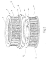
- the coupling device 30 illustrated in FIG. 2 is a changeover clutch, in which the rotationally fixed with the coupled continuous shaft not shown Clutch disc 15 alternatively either with the drive disc 11 or the drive disc 12 to couple is.
- the drive pulleys 11, 12 are toothed belt pulleys those with different speeds and / or in different Direction of rotation are driven.
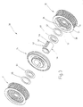
- the structure of the coupling device 30 goes in detail from Figures 2, 2a and 3.
- the drive pulleys 11, 12 are rotatable with the deep groove ball bearings 8, 9, however axially immovable only on that in Figure 4 indicated by its center line 6 'shaft 6 held.
- the drive pulleys 11, 12 are among themselves equally trained. They have a camp seat 31 for receiving the outer ring 32 of the respective deep groove ball bearing 8, 9 on.
- This approximately circular cylindrical Bearing seat 31 is in the radial direction extending web 33 with an annular outer portion 34 connected, which carries the teeth and on its two axial ends with a flange-like edge 35 is provided.
- the web 33 can be a closed disc be formed or have openings.
- annular interior 37 bounded in a Axial direction is open.
- figure 5 illustrates a total of five triangular in cross section trained fingers 38 arranged, which is different from the Bearing seat 31 extend in the axial direction and the Serve coupling elements.
- the fingers 38 form together with the portion of the drive pulley 12 that holds them a coupling half 12a.
- the fingers 38 are at a distance from the approximately cylindrical Arranged inner surface of the outer portion 34 and rounded on its side facing the inner surface, as can be seen in particular from FIG. 5. Also are it, as Figure 4 illustrates, at its free end rounded. Each closes axially extending Finger 38 approximately in a plane with the edge 35 of the outer section 34 from. The edge 35 defines one as an abutment serving radial ring surface. On its radially inner Each finger is 38 with a rectangular side or slightly acute-angled edge 39, the with the adjoining flanks 40 for coupling serves with the coupling piece 15.
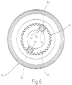
- That shown in Figures 3 and 4 and separately coupling piece 15 shown in FIG. 6 is a one-piece plastic body with a central hub 41, which has a central bore 42 with a cylindrical inner surface having.
- the hub 41 is on its radially outer one Side provided with a toothing 44 which is formed in this way is that with the fingers 38 of the drive pulleys 11, 12 can be brought into engagement. It thus forms a coupling half 15a.
- the toothing 44 extends itself over the entire length of the hub 41 to one radially outwardly extending disc-shaped Section 45, which is annular at the radially outer edge has thickened portion 46. This points a radial ring surface, which as a sling for Limitation of the clutch stroke is used.
- the dimensions of the hub 41 and the outer portion 46, i.e. the clutch stroke is in the axial direction matched so that the hub 41 axially some Millimeter protrudes beyond section 46. However is this protrusion is less than the length of the fingers 38 measured from the bearing seat 31 to its front The End. The protrusion defines the depth of engagement of the coupling device 30 firm.
- the coupling piece 15 To lock the coupling piece 15 in corresponding Coupling or separating positions serve two locking tongues 51, 52, the diametrically opposite one another Make the hub 41 are cut free.
- the latches 51, 52 are at one end on a radial Face of the hub connected to this while the spring the other end of the locking tongue 51 radially outwards can.
- the hub is 41 to this end provided with a corresponding cutout 53 which is open radially outwards.
- the resilient end of the locking tongue 51 (52) is provided with a curved locking section.
- the cutouts 53 interrupt the toothing 44. However, this does not affect the coupling effect. If a finger 38 is in the region of a recess 53, the power transmission through the other fingers 38 ensured.
- FIGS 3 and 4 illustrate between the drive disks 11, 12 as the coupling piece 15 sleeve-shaped made of plastic Spacer 57 arranged.
- the spacer 57 is rotatable with the Coupled shaft 6.
- the rib-like projections 59 are on their radially outer side with a sequence of transverse provide rounded recesses. Form this Locking recesses 61 for the rounded end of the tongue 51.
- the deep groove ball bearings 8, 9 are in contrast to that graphical representation in Fig. 3 sealed from the house.
- 12 cranked metal disks 64, 65 arranged for receiving, centering and storage serve from felt rings 66, 67. These may take from the Deep groove ball bearings 8, 9 towards the coupling device 30 exiting traces of fat, so that as little or no grease in the area of the fingers 38 or the teeth 44 arrives.
- the coupling device is on this Way kept dry. This counteracts river deposits.
- the coupling device 30 described so far works as follows:
- Both drive disks 11, 12 illustrated in Figure 4 Coupling device will be of appropriate Belt driven.
- the coupling piece 15 is, for example. coupled to the drive pulley 12 by moving it so far the drive pulley 12 is pushed up that its outer Section 46 on the edge 35 of the drive pulley 12 is present.
- the fingers 38 of the drive pulley grip 12 between the corresponding teeth of the toothing 44, but without with their end faces on the disc-shaped Section 45. Between the end faces of the Finger 38 and section 45 remain a lint space 70, which is not narrowed to a crack. So that will be Avoid fluff pressing into a compact deposit.
- a lint space 71 also remains between the End face 71 of the hub 41 and the deep groove ball bearing 5 or its sealing. By the left between the fingers 38 The fluff space 71 is radial through gaps open to the outside in the interior 37, which serves as a lint-receiving space can serve.
- the part of the drive pulley 11 belonging to Coupling device 30 is now open, so that can form deposits here.
- fluff is deposited on the toothing 44.
- the upper drive pulley 11 is now activated by the coupling piece 15 is moved up, push the total of five fingers 38 the lint from the corresponding Grooves of the teeth 44 in front of them without them to condense. This is because even in full engaged state a distance between the front ends of the fingers 38 and the disc-shaped Section 45 remains.
- the fluff pushed away can radially outward due to the rounding of the fingers 38 dodge. This is also supported by the centrifugal force when the clutch device 30 rotates.
- the fingers 38 can be on the face also have an inclined surface so that the finger 38 has a tip lying in the groove.
- any fluff packs pushed together can at the latest after switching the clutch if the annulus 37 is opened to the outside again by centrifugal force to be flung outwards so that the clutch device 30 has self-cleaning properties.
- the fluff spaces 70, 71 are kept clean in this way.
- the coupling device 30 is because of its open design also easy to clean, for example by using Compressed air is blown out.
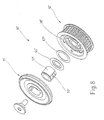
- Embodiment is a simple coupling device 30 'with only one drive pulley 12 '.
- the main difference from that described above Embodiment consists in the omission of the drive pulley 11.
- the drive pulley 12 ' is with the drive pulley 12 of the embodiment described above trained accordingly.
- the coupling piece 15 ' has only on one side a hub with the corresponding For which the description of the Coupling piece 15 applies accordingly.
- a thread delivery device is with a coupling device 30 provided with a drive pulley 12 if necessary a thread delivery wheel 7 to rotate.
- the coupling device 30 is designed in an open design, in which every training of condensing Is avoided.
- a coupling half has this axial fingers in the radially open longitudinal grooves of the grasp other coupling half by a toothing 44 are formed.
- the grooves of the toothing 44 are longer than the length of engagement between finger 38 and toothing 44.
- the between the end faces of the fingers 38 and the in The next wall formed in the axial direction is in Radial direction open or stands with a larger interior 37 in connection. This will compress or Avoid pressing of deposited lint.
Landscapes
- Engineering & Computer Science (AREA)
- Textile Engineering (AREA)
- Knitting Machines (AREA)
- Mechanical Operated Clutches (AREA)
- Pulleys (AREA)
- Unwinding Of Filamentary Materials (AREA)
- Spinning Or Twisting Of Yarns (AREA)
- Yarns And Mechanical Finishing Of Yarns Or Ropes (AREA)
- Details Of Spanners, Wrenches, And Screw Drivers And Accessories (AREA)
- Devices For Conveying Motion By Means Of Endless Flexible Members (AREA)
- Transmission Devices (AREA)
- Pens And Brushes (AREA)
Description
Claims (25)
- Kupplungseinrichtung (30), insbesondere für Fadenliefergeräte,dadurch gekennzeichnet, dass die Kupplungshälften (12a, 15a) derart ausgebildet sind, dass zwischen an den Kupplungselementen (38, 44) vorgesehenen oder diesen benachbarten, beim Einkuppeln aufeinander zu bewegten und der Flusablagerung zugänglichen Flächen der Kupplungshälften (12a, 15a) in eingekuppeltem Zustand ein offener Flusenraum (70, 71) verbleibt, der sowohl in eingekuppeltem als auch in ausgekuppeltem Zustand mit einem größeren, von der Umgebung getrennten Aufnahmeraum (37) oder der Umgebung in Verbindung steht.mit wenigstens einer ersten Kupplungshälfte (12a), die drehbar gelagert und mit einem Antriebsmittel (34) verbunden ist und die mit einem ersten formschlüssigen Kupplungselement (38) versehen ist,mit einer zweiten Kupplungshälfte (15a), die konzentrisch zu der ersten Kupplungshälfte (12a) drehbar gelagert mit einem Abtriebsmittel (6) verbunden ist und die mit einem zweiten formschlüssigen Kupplungselement (44) versehen ist,wobei wenigstens eine der Kupplungshälften (15a) axial bewegbar gelagert ist, so dass sie auf die jeweils andere Kupplungshälfte (12a) zu und von dieser weg verschoben werden kann, um die Kupplungselemente (38, 44) in und außer Eingriff zu bringen,
- Kupplungseinrichtung nach Anspruch 1, dadurch gekennzeichnet, dass der offene Flusenraum (70, 71) in Axialrichtung durch die aufeinander zu und voneinander weg bewegten Flächen der Kupplungshälften (12a, 15a) begrenzt ist und in Radialrichtung offen ist.
- Kupplungseinrichtung nach Anspruch 1, dadurch gekennzeichnet, dass die Axialbewegung der axial beweglich gelagerten Kupplungshälfte (15a) durch wenigstens ein Anschlagmittel (46) begrenzt ist, das mit der Kupplungshälfte (15a) verbunden ist und in eingekuppeltem Zustand mit einem entsprechenden Widerlager (35) in Anlage steht, das mit der anderen Kupplungshälfte (12a) verbunden ist.
- Kupplungseinrichtung nach Anspruch 3, dadurch gekennzeichnet, dass das Anschlagmittel (46) wenigstens eine radial außen angeordnete Fläche ist, die nach dem Einkuppeln der Kupplungshälften (12a, 15a) mit einer das Widerlager bildendenden zugeordneten Fläche in Anlage kommt und die weitere Axialbewegung der Kupplungshälften (12a, 15a) blockiert.
- Kupplungseinrichtung nach Anspruch 4, dadurch gekennzeichnet, dass die Anschlagmittel (46) und das Widerlager (35) Ringflächen sind.
- Kupplungseinrichtung nach Anspruch 4, dadurch gekennzeichnet, dass das Anschlagmittel (46) und das Widerlager (35) allenfalls in vollständig eingekuppeltem Zustand den Aufnahmeraum (37) in Radialrichtung nach außen gegen die Umgebung abschließen.
- Kupplungseinrichtung nach Anspruch 1, dadurch gekennzeichnet, dass die Kupplungselemente (38) freistehend ausgebildete, axial ausgerichtete Finger sind.
- Kupplungseinrichtung nach Anspruch 7, dadurch gekennzeichnet, dass das zweite Kupplungselement (44) durch axial angeordnete Nuten gebildet ist.
- Kupplungseinrichtung nach Anspruch 7 und 8, dadurch gekennzeichnet, dass die Finger (38) in gekuppeltem Zustand lediglich mit einem radial innen- oder außenliegenden Bereich mit den Nuten (44) in Eingriff stehen.
- Kupplungseinrichtung nach Anspruch 7 und 8, dadurch gekennzeichnet, dass die Kupplungseinrichtung (30) derart ausgebildet ist, dass die Finger (38) in eingekuppeltem Zustand über eine Länge mit den Nuten (44) in Eingriff stehen, die kürzer ist als die Länge der Nuten (44).
- Kupplungseinrichtung nach Anspruch 1, dadurch gekennzeichnet, dass die Kupplungselemente (38) in einem radial nach außen geschlossenen Aufnahmeraum (37) angeordnet sind, der in gekuppeltem Zustand in Axialrichtung durch die Kupplungshälften (12a, 15a) begrenzt ist.
- Kupplungseinrichtung nach Anspruch 1, dadurch gekennzeichnet, dass die freistehenden Kupplungselemente (38) an ihrer der anderen Kupplungshälfte (15) zugewandten Stirnseite abgerundet sind.
- Kupplungseinrichtung nach Anspruch 12, dadurch gekennzeichnet, dass die freistehenden Kupplungselemente (38) an ihrer den zugeordneten Kupplungselementen (44) abgewandten Seite abgeschrägt, abgerundet oder zugespitzt sind.
- Kupplungseinrichtung nach Anspruch 6, dadurch gekennzeichnet, dass die freistehenden Kupplungselemente (38) einen dreieckigen Querschnitt aufweisen.
- Kupplungseinrichtung nach Anspruch 14, dadurch gekennzeichnet, dass die zur Aufnahme der Kupplungselemente (38) vorgesehenen Kupplungselemente (44) dreieckige Nuten sind.
- Kupplungseinrichtung nach Anspruch 1, dadurch gekennzeichnet, dass die zur Aufnahme der Kupplungselemente (38) vorgesehenen Kupplungselemente durch eine Verzahnung (44) gebildet sind.
- Kupplungseinrichtung nach Anspruch 1, dadurch gekennzeichnet, dass die Kupplungselemente (38) in Abständen zueinander angeordnet sind, die größer sind, als die in Umfangsrichtung gemessene Breite jedes Kupplungselements (38).
- Kupplungseinrichtung nach Anspruch 1, dadurch gekennzeichnet, dass die axial verschiebbar gelagerte Kupplungshälfte (15) mit einer Fixiereinrichtung (51) wenigstens in Kuppelposition und in Trennposition axial in seiner Axialposition festlegbar ist.
- Kupplungseinrichtung nach Anspruch 18, dadurch gekennzeichnet, dass die Fixiereinrichtung (51, 61) wenigstens eine an einer Kupplungshälfte (15) ausgebildete Zunge aufweist, die sich in Axialrichtung erstreckt und die in Radialrichtung federnd gelagert ist.
- Kupplungseinrichtung nach Anspruch 19, dadurch gekennzeichnet, dass die Zunge als freigestellter Abschnitt einer Nabe (41) ausgebildet ist.
- Kupplungseinrichtung nach Anspruch 18, dadurch gekennzeichnet, dass die Fixiereinrichtung (51, 61) eine Rasteinrichtung ist.
- Kupplungseinrichtung nach Anspruch 1, dadurch gekennzeichnet, dass die Kupplungshälften (12, 15) mittels wenigstens eines Wälzlagers (9) drehbar aneinander gelagert sind und dass das Wälzlager (9) zu den Kupplungselementen (38, 44) hin abgedichtet sowie mit einem Aufnahmemittel (66, 67) für dennoch austretendes Schmiermittel versehen ist.
- Kupplungseinrichtung nach Anspruch 22, dadurch gekennzeichnet, dass das Wälzlager (9) mit seinem Innenring auf einer vorzugsweise als Abtriebsmittel dienenden Welle (6) sitzt, die eines der Kupplungselemente (15) trägt, und mit seinem Außenring die andere der Kupplungshälften (12) trägt und dass das Wälzlager (12) mittels einer Filzscheibe (67) abgedichtet ist, die zwischen dem Innenring des Wälzlagers (9) und wenigstens einem auf der Welle (6) sitzenden Profilstück (57) geklemmt ist, auf dem eine der Kupplungshälften (15) verschiebbar gelagert ist.
- Kupplungseinrichtung nach Anspruch 1, dadurch gekennzeichnet, dass die Kupplungseinrichtung (30) aus Kunststoffteilen besteht.
- Fadenliefergerät dadurch gekennzeichnet, dass es wenigstens eine Kupplungseinrichtung (30) nach einem der vorstehenden Ansprüche aufweist.
Applications Claiming Priority (2)
| Application Number | Priority Date | Filing Date | Title |
|---|---|---|---|
| DE19726027 | 1997-06-16 | ||
| DE19726027A DE19726027C2 (de) | 1997-06-19 | 1997-06-19 | Fadenliefergerät und Kupplungseinrichtung |
Publications (2)
| Publication Number | Publication Date |
|---|---|
| EP0885829A1 EP0885829A1 (de) | 1998-12-23 |
| EP0885829B1 true EP0885829B1 (de) | 2001-11-21 |
Family
ID=7833019
Family Applications (1)
| Application Number | Title | Priority Date | Filing Date |
|---|---|---|---|
| EP98110120A Expired - Lifetime EP0885829B1 (de) | 1997-06-19 | 1998-06-03 | Fadenliefergerät und Kupplungseinrichtung |
Country Status (23)
| Country | Link |
|---|---|
| US (1) | US5996756A (de) |
| EP (1) | EP0885829B1 (de) |
| JP (1) | JP3015341B2 (de) |
| KR (1) | KR100324841B1 (de) |
| CN (1) | CN1064643C (de) |
| BR (1) | BR9802026A (de) |
| CA (1) | CA2239527C (de) |
| CO (1) | CO4750734A1 (de) |
| CZ (1) | CZ190298A3 (de) |
| DE (2) | DE19726027C2 (de) |
| EA (1) | EA000446B1 (de) |
| EG (1) | EG22032A (de) |
| ES (1) | ES2163829T3 (de) |
| ID (1) | ID20464A (de) |
| MY (1) | MY132990A (de) |
| PE (1) | PE93298A1 (de) |
| PL (1) | PL185966B1 (de) |
| PT (1) | PT885829E (de) |
| SG (1) | SG65069A1 (de) |
| SK (1) | SK284516B6 (de) |
| TR (1) | TR199801108A3 (de) |
| TW (2) | TW500130U (de) |
| UA (1) | UA45427C2 (de) |
Families Citing this family (11)
| Publication number | Priority date | Publication date | Assignee | Title |
|---|---|---|---|---|
| US7133846B1 (en) | 1995-02-13 | 2006-11-07 | Intertrust Technologies Corp. | Digital certificate support system, methods and techniques for secure electronic commerce transaction and rights management |
| US7143290B1 (en) | 1995-02-13 | 2006-11-28 | Intertrust Technologies Corporation | Trusted and secure techniques, systems and methods for item delivery and execution |
| US6157721A (en) | 1996-08-12 | 2000-12-05 | Intertrust Technologies Corp. | Systems and methods using cryptography to protect secure computing environments |
| US5943422A (en) | 1996-08-12 | 1999-08-24 | Intertrust Technologies Corp. | Steganographic techniques for securely delivering electronic digital rights management control information over insecure communication channels |
| US7165174B1 (en) | 1995-02-13 | 2007-01-16 | Intertrust Technologies Corp. | Trusted infrastructure support systems, methods and techniques for secure electronic commerce transaction and rights management |
| US5892900A (en) | 1996-08-30 | 1999-04-06 | Intertrust Technologies Corp. | Systems and methods for secure transaction management and electronic rights protection |
| US7430670B1 (en) | 1999-07-29 | 2008-09-30 | Intertrust Technologies Corp. | Software self-defense systems and methods |
| EP3705248A4 (de) * | 2017-10-31 | 2021-08-18 | Koki Holdings Co., Ltd. | Elektrowerkzeug |
| CN111874743B (zh) * | 2020-08-11 | 2022-05-17 | 岳西神农氏农业科技有限公司 | 纺织机经线辊绕线导引机构 |
| CN113062036B (zh) * | 2021-03-17 | 2022-10-18 | 慈溪市赛美格自动化科技有限公司 | 一种可调速防卡死的输纱器 |
| CN118547415B (zh) * | 2024-07-30 | 2024-11-22 | 南通首禾纺织有限公司 | 一种纺织机用纱线传动装置 |
Family Cites Families (7)
| Publication number | Priority date | Publication date | Assignee | Title |
|---|---|---|---|---|
| US2992715A (en) * | 1959-08-27 | 1961-07-18 | Oster Mfg Co John | Readily separable torque transmitting coupling |
| DE1245654B (de) * | 1965-02-17 | 1967-07-27 | Maag Zahnraeder & Maschinen Ag | Zahnkupplung |
| DE2312933A1 (de) * | 1973-03-15 | 1974-09-19 | Iro Ab | Fadenliefervorrichtung fuer textilmaschinen |
| DE3042989A1 (de) * | 1980-11-14 | 1982-07-01 | Memminger Gmbh, 7290 Freudenstadt | Fadenliefervorrichtung fuer textilmaschinen |
| US4667867A (en) * | 1986-07-01 | 1987-05-26 | Gte Products Corporation | Wire bonding tool |
| DE4141712A1 (de) * | 1991-12-18 | 1993-06-24 | Heinz Fabschitz | Fadenliefereinrichtung fuer textilmaschinen |
| US5497867A (en) * | 1993-12-27 | 1996-03-12 | Eaton Corporation | Synchronizer with cone cup locater pins |
-
1997
- 1997-06-19 DE DE19726027A patent/DE19726027C2/de not_active Expired - Fee Related
- 1997-08-18 PE PE1997000724A patent/PE93298A1/es not_active Application Discontinuation
- 1997-08-21 CO CO97048190A patent/CO4750734A1/es unknown
-
1998
- 1998-05-13 UA UA98052456A patent/UA45427C2/uk unknown
- 1998-05-19 SG SG1998001073A patent/SG65069A1/en unknown
- 1998-06-01 US US09/088,538 patent/US5996756A/en not_active Expired - Fee Related
- 1998-06-01 CA CA002239527A patent/CA2239527C/en not_active Expired - Fee Related
- 1998-06-03 PT PT98110120T patent/PT885829E/pt unknown
- 1998-06-03 EP EP98110120A patent/EP0885829B1/de not_active Expired - Lifetime
- 1998-06-03 DE DE59802687T patent/DE59802687D1/de not_active Expired - Fee Related
- 1998-06-03 ES ES98110120T patent/ES2163829T3/es not_active Expired - Lifetime
- 1998-06-05 PL PL98326692A patent/PL185966B1/pl not_active IP Right Cessation
- 1998-06-05 ID IDP980832A patent/ID20464A/id unknown
- 1998-06-10 TW TW089208333U patent/TW500130U/zh not_active IP Right Cessation
- 1998-06-10 TW TW087109197A patent/TW503276B/zh not_active IP Right Cessation
- 1998-06-10 JP JP10161649A patent/JP3015341B2/ja not_active Expired - Fee Related
- 1998-06-16 TR TR1998/01108A patent/TR199801108A3/tr unknown
- 1998-06-17 CZ CZ981902A patent/CZ190298A3/cs unknown
- 1998-06-18 EA EA199800456A patent/EA000446B1/ru not_active IP Right Cessation
- 1998-06-18 CN CN98114986A patent/CN1064643C/zh not_active Expired - Lifetime
- 1998-06-18 BR BR9802026A patent/BR9802026A/pt not_active IP Right Cessation
- 1998-06-18 KR KR1019980022852A patent/KR100324841B1/ko not_active Expired - Fee Related
- 1998-06-18 EG EG69998A patent/EG22032A/xx active
- 1998-06-18 MY MYPI98002726A patent/MY132990A/en unknown
- 1998-06-19 SK SK869-98A patent/SK284516B6/sk unknown
Also Published As
| Publication number | Publication date |
|---|---|
| PT885829E (pt) | 2002-05-31 |
| DE19726027C2 (de) | 1999-05-06 |
| CA2239527C (en) | 2004-03-16 |
| UA45427C2 (uk) | 2002-04-15 |
| TW500130U (en) | 2002-08-21 |
| HK1017029A1 (en) | 1999-11-12 |
| KR19990007075A (ko) | 1999-01-25 |
| CN1204706A (zh) | 1999-01-13 |
| CN1064643C (zh) | 2001-04-18 |
| SG65069A1 (en) | 1999-05-25 |
| CO4750734A1 (es) | 1999-03-31 |
| TR199801108A2 (xx) | 1999-10-21 |
| EG22032A (en) | 2002-06-30 |
| TR199801108A3 (tr) | 1999-10-21 |
| SK86998A3 (en) | 1999-03-12 |
| MY132990A (en) | 2007-10-31 |
| KR100324841B1 (ko) | 2002-08-14 |
| TW503276B (en) | 2002-09-21 |
| CA2239527A1 (en) | 1998-12-19 |
| EP0885829A1 (de) | 1998-12-23 |
| DE59802687D1 (de) | 2002-02-21 |
| ID20464A (id) | 1998-12-24 |
| CZ190298A3 (cs) | 1999-01-13 |
| JPH11140750A (ja) | 1999-05-25 |
| US5996756A (en) | 1999-12-07 |
| BR9802026A (pt) | 1999-07-13 |
| ES2163829T3 (es) | 2002-02-01 |
| JP3015341B2 (ja) | 2000-03-06 |
| PL326692A1 (en) | 1998-12-21 |
| EA000446B1 (ru) | 1999-08-26 |
| SK284516B6 (sk) | 2005-05-05 |
| PL185966B1 (pl) | 2003-09-30 |
| PE93298A1 (es) | 1999-01-14 |
| DE19726027A1 (de) | 1999-01-28 |
| EA199800456A1 (ru) | 1998-12-24 |
Similar Documents
| Publication | Publication Date | Title |
|---|---|---|
| DE2843198C2 (de) | ||
| DE3012152C2 (de) | Haltevorrichtung für ein rotierendes zahnärztliches Werkzeug | |
| DE19843946A1 (de) | Riemenscheibeneinheit | |
| DE1756340A1 (de) | Tragrolle fuer Foerdereinrichtungen | |
| DE3914120A1 (de) | Rotationsteil mit einwegkupplung | |
| DE3903676C2 (de) | ||
| DE19726027C2 (de) | Fadenliefergerät und Kupplungseinrichtung | |
| DE2803925A1 (de) | Aufloesewalze | |
| DE2328462C2 (de) | Schlagbohrmaschine | |
| DE4207329C2 (de) | ||
| DE102015113099A1 (de) | Spannzangenfutter mit Wälzkörpergewindetrieb | |
| EP2319287B1 (de) | Verbindungsanordnung zum Verbinden eines Mähmesserantriebs mit einem Mähmesser | |
| EP1121537A1 (de) | Wälzlager | |
| DE19537561A1 (de) | Werkzeughalter | |
| DE3028467A1 (de) | Gelenk fuer ein drehmoment nach beiden drehrichtungen uebertragende wellen oder dergleichen | |
| DE202016002577U1 (de) | Maschine mit drehbar gelagerter Welle | |
| DE19922325C1 (de) | Schaltmuffenträger | |
| DE19824286A1 (de) | Lagerung für einen Offenend-Spinnrotor mittels Stützscheiben | |
| DE2121182C3 (de) | Kupplungsriemenscheibe für einen Riementrieb | |
| EP3433502B1 (de) | Medizinische vorrichtung | |
| DE3502283A1 (de) | Einspurtrieb fuer den anlasser eines verbrennungsmotors | |
| EP0717666B1 (de) | Stufenlos verstellbarer bürstenträger | |
| DE2808698A1 (de) | Vorrichtung zur langzeit-lagerschmierung | |
| DE10130898C2 (de) | Handstück für ein medizinisches oder kosmetisches Bearbeitungsgerät | |
| DE4129111A1 (de) | Kaefig fuer rollenlager |
Legal Events
| Date | Code | Title | Description |
|---|---|---|---|
| PUAI | Public reference made under article 153(3) epc to a published international application that has entered the european phase |
Free format text: ORIGINAL CODE: 0009012 |
|
| 17P | Request for examination filed |
Effective date: 19981023 |
|
| AK | Designated contracting states |
Kind code of ref document: A1 Designated state(s): DE ES FR GB GR IT PT |
|
| AX | Request for extension of the european patent |
Free format text: AL;LT PAYMENT 981023;LV PAYMENT 981023;MK;RO PAYMENT 981023;SI |
|
| AKX | Designation fees paid |
Free format text: DE ES FR GB GR IT PT |
|
| AXX | Extension fees paid |
Free format text: LT PAYMENT 19981023;LV PAYMENT 19981023;RO PAYMENT 19981023 |
|
| GRAG | Despatch of communication of intention to grant |
Free format text: ORIGINAL CODE: EPIDOS AGRA |
|
| GRAG | Despatch of communication of intention to grant |
Free format text: ORIGINAL CODE: EPIDOS AGRA |
|
| GRAH | Despatch of communication of intention to grant a patent |
Free format text: ORIGINAL CODE: EPIDOS IGRA |
|
| 17Q | First examination report despatched |
Effective date: 20010214 |
|
| GRAH | Despatch of communication of intention to grant a patent |
Free format text: ORIGINAL CODE: EPIDOS IGRA |
|
| GRAA | (expected) grant |
Free format text: ORIGINAL CODE: 0009210 |
|
| AK | Designated contracting states |
Kind code of ref document: B1 Designated state(s): DE ES FR GB GR IT PT |
|
| AX | Request for extension of the european patent |
Free format text: LT PAYMENT 19981023;LV PAYMENT 19981023;RO PAYMENT 19981023 |
|
| PG25 | Lapsed in a contracting state [announced via postgrant information from national office to epo] |
Ref country code: GR Free format text: LAPSE BECAUSE OF FAILURE TO SUBMIT A TRANSLATION OF THE DESCRIPTION OR TO PAY THE FEE WITHIN THE PRESCRIBED TIME-LIMIT Effective date: 20011121 |
|
| REG | Reference to a national code |
Ref country code: GB Ref legal event code: IF02 |
|
| REG | Reference to a national code |
Ref country code: ES Ref legal event code: FG2A Ref document number: 2163829 Country of ref document: ES Kind code of ref document: T3 |
|
| ET | Fr: translation filed | ||
| REF | Corresponds to: |
Ref document number: 59802687 Country of ref document: DE Date of ref document: 20020221 |
|
| GBT | Gb: translation of ep patent filed (gb section 77(6)(a)/1977) |
Effective date: 20020216 |
|
| REG | Reference to a national code |
Ref country code: GR Ref legal event code: EP Ref document number: 20010402181 Country of ref document: GR |
|
| REG | Reference to a national code |
Ref country code: PT Ref legal event code: SC4A Free format text: AVAILABILITY OF NATIONAL TRANSLATION Effective date: 20020207 |
|
| PLBE | No opposition filed within time limit |
Free format text: ORIGINAL CODE: 0009261 |
|
| STAA | Information on the status of an ep patent application or granted ep patent |
Free format text: STATUS: NO OPPOSITION FILED WITHIN TIME LIMIT |
|
| 26N | No opposition filed | ||
| PGFP | Annual fee paid to national office [announced via postgrant information from national office to epo] |
Ref country code: GB Payment date: 20050519 Year of fee payment: 8 |
|
| PGFP | Annual fee paid to national office [announced via postgrant information from national office to epo] |
Ref country code: PT Payment date: 20050602 Year of fee payment: 8 |
|
| PGFP | Annual fee paid to national office [announced via postgrant information from national office to epo] |
Ref country code: FR Payment date: 20050621 Year of fee payment: 8 |
|
| PGFP | Annual fee paid to national office [announced via postgrant information from national office to epo] |
Ref country code: GR Payment date: 20050628 Year of fee payment: 8 Ref country code: ES Payment date: 20050628 Year of fee payment: 8 |
|
| PG25 | Lapsed in a contracting state [announced via postgrant information from national office to epo] |
Ref country code: GB Free format text: LAPSE BECAUSE OF NON-PAYMENT OF DUE FEES Effective date: 20060603 |
|
| PG25 | Lapsed in a contracting state [announced via postgrant information from national office to epo] |
Ref country code: ES Free format text: LAPSE BECAUSE OF NON-PAYMENT OF DUE FEES Effective date: 20060605 |
|
| PG25 | Lapsed in a contracting state [announced via postgrant information from national office to epo] |
Ref country code: PT Free format text: LAPSE BECAUSE OF NON-PAYMENT OF DUE FEES Effective date: 20061204 |
|
| LTLA | Lt: lapse of european patent or patent extension |
Effective date: 20060603 |
|
| REG | Reference to a national code |
Ref country code: PT Ref legal event code: MM4A Free format text: LAPSE DUE TO NON-PAYMENT OF FEES Effective date: 20061204 |
|
| GBPC | Gb: european patent ceased through non-payment of renewal fee |
Effective date: 20060603 |
|
| REG | Reference to a national code |
Ref country code: FR Ref legal event code: ST Effective date: 20070228 |
|
| REG | Reference to a national code |
Ref country code: ES Ref legal event code: FD2A Effective date: 20060605 |
|
| PG25 | Lapsed in a contracting state [announced via postgrant information from national office to epo] |
Ref country code: FR Free format text: LAPSE BECAUSE OF NON-PAYMENT OF DUE FEES Effective date: 20060630 |
|
| PGFP | Annual fee paid to national office [announced via postgrant information from national office to epo] |
Ref country code: DE Payment date: 20080827 Year of fee payment: 11 |
|
| PGFP | Annual fee paid to national office [announced via postgrant information from national office to epo] |
Ref country code: IT Payment date: 20080626 Year of fee payment: 11 |
|
| PG25 | Lapsed in a contracting state [announced via postgrant information from national office to epo] |
Ref country code: DE Free format text: LAPSE BECAUSE OF NON-PAYMENT OF DUE FEES Effective date: 20100101 |
|
| PG25 | Lapsed in a contracting state [announced via postgrant information from national office to epo] |
Ref country code: IT Free format text: LAPSE BECAUSE OF NON-PAYMENT OF DUE FEES Effective date: 20090603 |