EP0885137B1 - Verstellvorrichtung für zumindest zwei rückblickspiegel eines fahrzeugs - Google Patents
Verstellvorrichtung für zumindest zwei rückblickspiegel eines fahrzeugs Download PDFInfo
- Publication number
- EP0885137B1 EP0885137B1 EP97902234A EP97902234A EP0885137B1 EP 0885137 B1 EP0885137 B1 EP 0885137B1 EP 97902234 A EP97902234 A EP 97902234A EP 97902234 A EP97902234 A EP 97902234A EP 0885137 B1 EP0885137 B1 EP 0885137B1
- Authority
- EP
- European Patent Office
- Prior art keywords
- mirror
- adjustment
- servomotors
- adjustment device
- actuating
- Prior art date
- Legal status (The legal status is an assumption and is not a legal conclusion. Google has not performed a legal analysis and makes no representation as to the accuracy of the status listed.)
- Expired - Lifetime
Links
- 230000008054 signal transmission Effects 0.000 claims description 10
- 230000007246 mechanism Effects 0.000 claims description 7
- 238000010276 construction Methods 0.000 claims description 3
- 230000005540 biological transmission Effects 0.000 claims 3
- 230000006978 adaptation Effects 0.000 description 3
- 238000004519 manufacturing process Methods 0.000 description 3
- 230000008859 change Effects 0.000 description 2
- 238000011161 development Methods 0.000 description 2
- 230000018109 developmental process Effects 0.000 description 2
- 238000005516 engineering process Methods 0.000 description 2
- 230000010354 integration Effects 0.000 description 2
- 238000013519 translation Methods 0.000 description 2
- 230000014616 translation Effects 0.000 description 2
- 230000004438 eyesight Effects 0.000 description 1
- 230000004313 glare Effects 0.000 description 1
- 230000006872 improvement Effects 0.000 description 1
- 230000003993 interaction Effects 0.000 description 1
- 238000002372 labelling Methods 0.000 description 1
- 230000003287 optical effect Effects 0.000 description 1
- 230000009466 transformation Effects 0.000 description 1
- 230000001960 triggered effect Effects 0.000 description 1
Images

Classifications
-
- B—PERFORMING OPERATIONS; TRANSPORTING
- B60—VEHICLES IN GENERAL
- B60R—VEHICLES, VEHICLE FITTINGS, OR VEHICLE PARTS, NOT OTHERWISE PROVIDED FOR
- B60R1/00—Optical viewing arrangements; Real-time viewing arrangements for drivers or passengers using optical image capturing systems, e.g. cameras or video systems specially adapted for use in or on vehicles
- B60R1/02—Rear-view mirror arrangements
- B60R1/06—Rear-view mirror arrangements mounted on vehicle exterior
- B60R1/062—Rear-view mirror arrangements mounted on vehicle exterior with remote control for adjusting position
- B60R1/07—Rear-view mirror arrangements mounted on vehicle exterior with remote control for adjusting position by electrically powered actuators
Definitions
- the invention relates to an adjustment device for at least two rear view mirrors Vehicle according to the preamble of patent claim 1.
- JP-60-050048-A and JP-02-106452-A are generic adjusting devices become known in which the common adjustment by means of a selector switch at least two rearview mirrors can be made.
- the selector units are designed so that in addition to the switch position for the common adjustment two additional switch positions are provided for the separate individual actuation of the rearview mirror is.
- a selector switch the structure of which is fundamentally different from those two-stage selector units, as they are sufficient in vehicle construction for ordinary mirror adjustment are known.
- JP-58-206441-A describes an adjustment device for rear view mirrors which is used for automatic Adjustment of two rearview mirrors as an actuator shows an interior rearview mirror.
- the position sensors assigned by the interior rear view mirror are those of the vehicle driver made adjustment of the interior rear view mirror for automatic co-adjustment of the two exterior rear-view mirrors.
- DE-34 06 286-C1 describes how to adjust two rearview mirrors together only a single adjustment on an actuator is required.
- the centerpiece of the device described there is a comparator circuit which ensures that when setting a first rearview mirror (preferably that on the driver’s side) the second rearview mirror (preferably the one on the passenger side) automatically so is also adjusted that it is also optimally adjusted to the driver's eye position.
- a first rearview mirror preferably that on the driver’s side
- the second rearview mirror preferably the one on the passenger side
- Rear-view mirrors must be taken into account. This is done there by means of a separate Transformation circuit that with the aforementioned comparator circuit cooperates.
- the overall to be regarded as advantageous in terms of operation Adjustment device requires a complex one to implement the basic functions Sensor technology and control electronics.
- the common adjustment of at least two rearview mirrors is in principle also from the DE-42 41 543-A1 (B60R 1/06) known. There, however, is the common adjustment from a so-called use position to an angle-swiveled dipped position performed. So it's about the glare for an operator of a vehicle to be able to prevent precisely when coming from vehicles traveling with light reflections are generated in the rear view mirrors, especially at night. The However, the dipped positions of the two rearview mirrors are not at an angle coordinated.
- the invention has for its object to develop generic adjusting devices so that either with a reduced apparatus and circuitry Effort a comparable function can be realized or with comparable effort an improvement of the automated with regard to a driver-specific adaptation Fine adjustment is possible.
- a first solution variant for the purpose of common adjustment of at least two rearview mirrors the associated actuators a corresponding control signal from an actuating element.
- the setting is made by a signal transmission device Control signal converted, which is fed to both servomotors.
- the subsequent one common movement of the mirror elements takes place in a predetermined relationship to each other.
- the inventor has come to the conclusion that those in the generic Document described relationships with regard to different Characteristic curves when adjusting rear-view mirrors essentially to one linear relationship acceptable for the operator of a vehicle can be.
- the second mirror element in proportional dependence on the setting of the first mirror element.
- a ratio can be set in the adjusting device according to the invention over a specified speed difference with the same adjustment time Actuators or vice versa at constant speed of both actuators using different Running time.
- the gear ratios can also be used arranged between the servomotors and the mirror elements Swivel and / or tilt mechanisms can be coordinated with each other in a vehicle-specific manner.
- a second solution variant which advantageously with the first solution variant can be combined, provides a selector switch unit within the scope of the actuating device, in which a so-called "right and left mode" is specified in a basic setting is.
- the rearview mirror can be used to set a vehicle or driver-specific field of vision on the passenger side for left-hand drive vehicles in a second selector position separately, that is, in a "right-only mode", and without adjusting the rearview mirror can be set on the driver side. Then for normal driving then the common adjustment by switching back to the first selection position both rearview mirrors are made.
- the adjustment device according to the invention advantageously enables use conventional push button switch, as described, for example, in EP-0 400 633-A2 (H01H 25/04) or in DE-42 13 133-C1 (B60R 1/06).
- the particular one Integration of a selector switch into the as described in the latter document Actuator executed push button switch can be advantageously in the inventive Adjustment device can be used.
- FIG. 1 shows a vehicle with a left-hand drive design, designated overall by 1, the components essential for the adjustment device according to the invention here an outside mirror 2 on the driver side, an outside mirror 3 on the passenger side and a Interior rearview mirror 4 are.
- an actuating device 8 On a driver's seat 6 having a backrest 5 there is a person 7 as the operator of the vehicle 1, by means of an actuating device 8 the positions of the exterior mirrors 2, 3 and in a special one Comfortable design, if necessary, the interior rear view mirror 4 can be adjusted.
- the actuator 8 assigned to a control panel of a center console 9, which is not further numbered here.
- the actuating device 8 is not relocated here shown trim part of a driver's door 10. It becomes explicit at this point noted that the adjustment device according to the invention both in Left-hand drive as well as right-hand drive vehicles can be used. It will therefore be at this Do not put right and left mirrors, but mirrors on the driver or passenger side spoken.
- FIG. 2 shows housings 11, 12 for the exterior mirrors 2 and 3, in which Mirror elements 13, 14 around, for example, swivel bearings designed as ball joints 15, 16 according to the arrows A, B pivotable and about axes of rotation 17, 18 according to the Rotary arrows C, D are tiltable.
- servomotors 18, 19 both of a signal transmission device 20 can be controlled.
- As a mechanism for adjustment the mirror elements 13, 14 are only schematically indicated adjustment spindles 21, 22 provided. For reasons of clarity, servomotors are to be realized the tilting movements about the axes C and D are not shown here.
- One on the face of the selector switch 24 applied marking in the form of a splash of color and / or a nub-like elevation shows the respective first position as the selected position.
- the "right and left mode” is set. This mode is called the home position here.
- By twisting the Selector switch 24 in the clockwise direction can be the so-called "right-only mode" as the second dial position. can be set.
- the selector switch is designed as a rotary switch.
- one can Arrangement of two pressure switches can be realized, by pressing one Pressure switch the first selector position and by pressing the second pressure switch the second dial position is specified (see, for example, the one above mentioned DE-42 13 133-C1).
- the interior rearview mirror 4 as Actuator can be used.
- position measuring sensors 28, 29 necessary due to the movements of the interior rearview mirror 4 about a pivot axis 30 according to the rotation arrow E or tilting movements about a tilt axis 31 according to the rotation arrow F can be identified as actuating movements.
- the actuating element 8 is omitted.
- a third is also conceivable To provide a rest position to select an "interior rear view mirror mode" can.
- signals can also be transmitted to the signal transmission device 20 a backrest inclination sensor 32 and a driver's seat position sensor 33 are supplied, so that the setting made on the interior rear-view mirror 4 is even better to be able to adapt the respective shape of the person 7.
- a warning device may also be formed, the incorrect settings on the interior rear-view mirror 4 automatically in relation to the respective position of the vehicle operator 7 signaled via acoustic or optical detectors.
- the signal can only be one of the two sensors 32, 33 are already decisive.
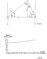
- FIG. 3 The geometric relationships for the mirror arrangement shown in FIG. 2 are illustrated in FIG. 3.
- the respective width of a motor vehicle determines the amount of the route "a + b".
- the arrangement of the driver's seat with respect to the central axis of the respective vehicle determines the amount of the quotient a / b.
- An angle adjustment of the mirror element 13 would thus be one of the ratio between the mirror element 14 the amount corresponding to the translations of the adjusting spindles 21, 22 larger fail, so that an optimal mirror adjustment is also made on the passenger side becomes.
Landscapes
- Engineering & Computer Science (AREA)
- Multimedia (AREA)
- Mechanical Engineering (AREA)
- Rear-View Mirror Devices That Are Mounted On The Exterior Of The Vehicle (AREA)
Description
- Figur 1:
- in Ausschnitten am Beispiel eines Personenkraftfahrzeuges die grundsätzlichen Ausgangsvoraussetzungen für die Verwendung einer erfindungsgemäßen Verstellvorrichtung,
- Figur 2:
- in schematischer Darstellung eine erfindungsgemäße Verstellvorrichtung,
- Figur 3:
- die geometrischen Verhältnisse für Rückblickspiegelanordnungen in einem Fahrzeug gemäß Figur 1 und
- Figur 4:
- den aus Figur 3 bestimmten Zusammenhang zwischen den Winkellagen zweier Außenspiegel.
Claims (8)
- Verstellvorrichtung für zumindest zwei Rückblickspiegel (2, 3) eines Fahrzeugs mitdadurch gekennzeichnet, daßStellmotoren (18; 19) zur Positionierung von Spiegelelementen (13, 14) mittels eines Schwenk- und/oder Kippmechanismus (21, 22),einer Betätigungseinrichtung zur Erzeugung von Stellsignalen für die gemeinsame Aktivierung der Stellmotoren (18, 19),wenigstens einer der Betätigungseinrichtung (8) zugeordneten Wähl schalteinheit (24), durch die eine gemeinsame Betätigung wenigstens zweier Spiegelelemente (13 und 14) und eine gesonderte Positionierbarkeit nur eines der Spiegelelemente (13 oder 14) vorgebbar ist,wenigstens einer Signalübertragungseinrichtung (20) zwischen der Betätigungseinrichtung (8) und den Stellmotoren (18, 19),für die Spiegelverstellung mittels eines Tastschalters (23) die Wählschalteinheit (24) zwischen nur zwei Wählstellungen umschaltbar ist,die eine der beiden Wählstellungen der gemeinsamen Betätigung der wenigstens zwei Spiegelelemente (13 und 14) zugewiesen ist,die andere der beiden Wählstellungen der gesonderten Positionierbarkeit nur eines der Spiegelelemente (13 oder 14) zugewiesen ist,durch die andere der beiden Wählstellungen das Spiegelelement (13 oder 14) auf der Beifahrerseite gesondert positionierbar ist.
- Verstellvorrichtung nach Anspruch 1,
dadurch gekennzeichnet, daß die wenigstens zwei Spiegelelemente (13,14) durch die Stellmotoren (18, 19) bei der gemeinsamen Betätigung im Verhältnis 1:1 verstellbar sind. - Verstellvorrichtung nach Anspruch 1,
gekennzeichnet durchzwei baugleiche Stellmotoren,je ein den Stellmotoren zugeordnetes, schneckenrad- oder stirnradartig ausgebildetes Getriebe im Schwenk- und/oder Kippmechanismus,ein im wesentlichen proportionales Verhältnis zwischen den Übersetzungen der Getriebe. - Verstellvorrichtung nach Anspruch 1 oder 2,
dadurch gekennzeichnet, daß die Betätigungseinrichtung integraler Bestandteil eines Innenrückblickspiegels (4) ist. - Verstellvorrichtung nach Anspruch 1 oder 4,
dadurch gekennzeichnet, daßder Innenrückblickspiegel (4) ein Bestandteil der Betätigungseinrichtung ist,die Wählschalteinheit zur Spiegelverstellung durch den Tastschalter (23) und zur Wählbarkeit des Innenrückblickspiegels (4) als Betätigungselement hergrichtet ist,zur Wählbarkeit des Innenrückblickspiegels (4) als Betätigungselement die Wählschalteinheit (24) in eine dritte Wählstellung umschaltbar ist,der Signalübertragungseinrichtung (20) Signale einer Lagesensoreinrichtung (28, 29) zuführbar sind, durch die die Einstellposition des Innenrückblickspiegels (4) erfaßbar ist. - Verstellvorrichtung nach Anspruch 1,
dadurch gekennzeichnet, daß in der Betätigungseinrichtung (8) der Wählschalter (24) mit dem Tastschalter (23) zu einer Baueinheit zusammengefaßt ist. - Verstellvorrichtung nach Anspruch 1,
dadurch gekennzeichnet, daß der Signalübertragungseinrichtung (20) ein Signal eines ersten Sensors (33) zuführbar ist, durch den die Position eines Fahrersitzes (6) erfaßbar ist. - Verstellvorrichtung nach Anspruch 1 oder 7,
dadurch gekennzeichnet, daß der Signalübertragungseinrichtung (20) ein Signal eines zweiten Sensors (32) zuführbar ist, durch den die Neigung einer Rückenlehne (5) des Fahrersitzes (6) erfaßbar ist.
Applications Claiming Priority (3)
| Application Number | Priority Date | Filing Date | Title |
|---|---|---|---|
| DE19603879 | 1996-02-03 | ||
| DE19603879 | 1996-02-03 | ||
| PCT/EP1997/000356 WO1997028021A1 (de) | 1996-02-03 | 1997-01-28 | Verstellvorrichtung für zumindest zwei rückblickspiegel eines fahrzeugs |
Publications (2)
| Publication Number | Publication Date |
|---|---|
| EP0885137A1 EP0885137A1 (de) | 1998-12-23 |
| EP0885137B1 true EP0885137B1 (de) | 2001-10-10 |
Family
ID=7784409
Family Applications (1)
| Application Number | Title | Priority Date | Filing Date |
|---|---|---|---|
| EP97902234A Expired - Lifetime EP0885137B1 (de) | 1996-02-03 | 1997-01-28 | Verstellvorrichtung für zumindest zwei rückblickspiegel eines fahrzeugs |
Country Status (5)
| Country | Link |
|---|---|
| US (1) | US6154328A (de) |
| EP (1) | EP0885137B1 (de) |
| JP (1) | JP4315467B2 (de) |
| DE (1) | DE59704873D1 (de) |
| WO (1) | WO1997028021A1 (de) |
Families Citing this family (8)
| Publication number | Priority date | Publication date | Assignee | Title |
|---|---|---|---|---|
| US5801823A (en) * | 1997-02-21 | 1998-09-01 | Brandin; Boerje A. | Driver's eyes location determining apparatus and method |
| FR2788475B1 (fr) * | 1999-01-20 | 2001-03-02 | Renault | Dispositif pour le reglage de retrovisseurs d'un vehicule automobile |
| AUPR906001A0 (en) * | 2001-11-26 | 2001-12-20 | Schefenacker Vision Systems Australia Pty Ltd | Multi function mirror control switch |
| US6840637B2 (en) * | 2002-12-09 | 2005-01-11 | General Motors Corporation | Exterior rearview mirror system |
| US7373249B2 (en) * | 2004-11-02 | 2008-05-13 | Honda Motor Co., Ltd. | Automatic mirror stabilization |
| US20070030581A1 (en) * | 2005-08-05 | 2007-02-08 | Jenne-Tai Wang | Rear vision system with automatic blind zone and glare elimination function |
| US8087791B2 (en) * | 2009-04-15 | 2012-01-03 | Toyota Motor Engineering And Manufacturing North America, Inc. | Methods and systems for adjusting the position of vehicle outside mirrors |
| WO2023139600A1 (en) * | 2022-01-18 | 2023-07-27 | INDIAN INSTITUTE OF TECHNOLOGY MADRAS (IIT Madras) | Method and side-view mirror system of vehicle for monitoring ambient parameters during vehicle mobility |
Family Cites Families (29)
| Publication number | Priority date | Publication date | Assignee | Title |
|---|---|---|---|---|
| US4811226A (en) * | 1980-09-30 | 1989-03-07 | Toyota Jidosha Kogyo Kabushiki Kaisha | Optimum angle adjusting apparatus for vehicle equipments |
| JPS5889433A (ja) * | 1981-11-19 | 1983-05-27 | Honda Motor Co Ltd | フエスダ−ミラ−自動設定装置 |
| JPS58206441A (ja) * | 1982-05-28 | 1983-12-01 | Kanto Jidosha Kogyo Kk | フエンダ−ミラ−の自動調整装置 |
| JPS59230838A (ja) * | 1983-06-13 | 1984-12-25 | Nippon Soken Inc | シ−ト連動ミラ−角度調整装置 |
| JPS6050048A (ja) * | 1983-08-30 | 1985-03-19 | Mazda Motor Corp | 自動車のバツクミラ−装置 |
| JPS6092134A (ja) * | 1983-10-24 | 1985-05-23 | Ikeda Bussan Co Ltd | サイドミラ−の制御装置 |
| DE3406286C1 (de) * | 1984-02-22 | 1985-08-14 | Adam Opel AG, 6090 Rüsselsheim | Rückspiegelanordnung in Kraftfahrzeugen |
| JPH0323876Y2 (de) * | 1985-03-23 | 1991-05-24 | ||
| JPS6231540A (ja) * | 1985-08-05 | 1987-02-10 | Honda Motor Co Ltd | 自動車用ミラ−の駆動方法 |
| JPS62234754A (ja) * | 1986-03-31 | 1987-10-15 | Nec Home Electronics Ltd | ミラ−調整装置 |
| JPS62286855A (ja) * | 1986-06-04 | 1987-12-12 | Fujitsu Ten Ltd | 自動車用サイドミラ−の角度設定装置 |
| DE3713218A1 (de) * | 1987-04-18 | 1988-11-03 | Bayerische Motoren Werke Ag | Verfahren zum bestimmen der augen- und/oder kopfposition eines fahrzeug-benutzers |
| JPH02106462A (ja) * | 1988-10-13 | 1990-04-18 | Kobe Steel Ltd | レール走行車両の制動力低下判定方法 |
| JPH02106452A (ja) * | 1988-10-14 | 1990-04-18 | Omron Tateisi Electron Co | 電動サイドミラー制御装置 |
| JPH02234858A (ja) * | 1989-03-07 | 1990-09-18 | Tokai Rika Co Ltd | 自動車用電動ミラー装置 |
| DE69022118T2 (de) * | 1989-05-30 | 1996-02-15 | Ichiko Industries Ltd | Fernsteuerungsschalter für die Lageeinstellung von Kraftfahrzeugspiegeln. |
| DE3925978A1 (de) * | 1989-08-05 | 1991-02-07 | Konrad Hendlmeier | Kraftfahrzeug-aussenspiegel |
| JPH03153432A (ja) * | 1989-11-07 | 1991-07-01 | Kentaro Shioda | 後写鏡装置 |
| DE4008641A1 (de) * | 1990-03-17 | 1991-09-19 | Daimler Benz Ag | Steuervorrichtung zur handverstellung von reversierbaren elektrischen verstelleinrichtungen |
| DE4241543A1 (en) * | 1991-12-18 | 1993-06-24 | Klik Buehnensysteme | Adjustment device for motor vehicle's rear=view mirrors - has remotely controlled drive for tilting each reflector rapidly and precisely between operative and dipped positions |
| DE4213133C1 (de) * | 1992-04-21 | 1993-10-07 | Audi Ag | Spiegelversteller für einen linken und rechten Außenspiegel eines Kraftfahrzeugs |
| JPH0664480A (ja) * | 1992-08-18 | 1994-03-08 | Toyota Motor Corp | アウタミラー制御装置 |
| JPH06278534A (ja) * | 1993-03-29 | 1994-10-04 | Nissan Shatai Co Ltd | 車両用後方ミラーの自動調整装置 |
| GB2279631A (en) * | 1993-06-22 | 1995-01-11 | Peter Cecil Cummins | Swing-out mirrors |
| JPH10509933A (ja) * | 1994-11-25 | 1998-09-29 | アー. ブランディン,バーティル | リアビューミラーの調節を自動化する方法及び装置 |
| US5694259A (en) * | 1995-01-10 | 1997-12-02 | Brandin; Bertil A. | Apparatus for automating the adjustment of rearview mirrors |
| US5706144A (en) * | 1994-11-25 | 1998-01-06 | Brandin; Bertil A. | Methods and apparatus for automating the adjustment of rearview mirrors |
| US5668675A (en) * | 1995-01-18 | 1997-09-16 | Fredricks; Ronald J. | Opto-electronic aid for alignment of exterior vehicle mirrors to minimize blind spot effects |
| US5798575A (en) * | 1996-07-11 | 1998-08-25 | Donnelly Corporation | Vehicle mirror digital network and dynamically interactive mirror system |
-
1997
- 1997-01-28 WO PCT/EP1997/000356 patent/WO1997028021A1/de not_active Ceased
- 1997-01-28 DE DE59704873T patent/DE59704873D1/de not_active Expired - Lifetime
- 1997-01-28 JP JP52728597A patent/JP4315467B2/ja not_active Expired - Fee Related
- 1997-01-28 EP EP97902234A patent/EP0885137B1/de not_active Expired - Lifetime
-
1998
- 1998-07-23 US US09/121,287 patent/US6154328A/en not_active Expired - Lifetime
Also Published As
| Publication number | Publication date |
|---|---|
| JP2000503934A (ja) | 2000-04-04 |
| JP4315467B2 (ja) | 2009-08-19 |
| DE59704873D1 (de) | 2001-11-15 |
| US6154328A (en) | 2000-11-28 |
| EP0885137A1 (de) | 1998-12-23 |
| WO1997028021A1 (de) | 1997-08-07 |
Similar Documents
| Publication | Publication Date | Title |
|---|---|---|
| EP1077832B1 (de) | Fahrzeugsitz mit einer durch die grösse des benutzers beeinflussten sensorik geführten kopfstütze | |
| DE19725175C2 (de) | Innenausstattungsteil eines Fahrzeuges mit beweglichem Bedienfeld | |
| DE19744382B4 (de) | Multifunktionsanzeige für Kraftfahrzeuge | |
| DE102017212686B4 (de) | Lenkvorrichtung für ein Kraftfahrzeug, Verfahren zum Betreiben einer Lenkvorrichtung, Steuereinrichtung, und Kraftfahrzeug | |
| DE69703713T2 (de) | Schalten von einem Reisegeschwindigkeits-Steuerungssystem mit Fahrzeugfolgemodalität | |
| DE4409046A1 (de) | Vorrichtung zum Einstellen der Lage und/oder Winkelstellung von Fahrzeugeinrichtungen | |
| DE102007015877A1 (de) | Abbildungseinrichtung und Verfahren zur Abbildung | |
| DE10144476A1 (de) | Kraftfahrzeuglenksäuleneinheit mit verstellbarer Lenksäule | |
| DE19749214C1 (de) | Bedieneinheit zum Einstellen von Heizungs-, Klima- und/oder Lüftungsanlagen in Kraftfahrzeugen | |
| EP1111488B1 (de) | Kameraeinrichtung für ein Fahrzeug | |
| DE3627438C2 (de) | ||
| EP0885137A1 (de) | Verstellvorrichtung für zumindest zwei rückblickspiegel eines fahrzeugs | |
| DE19947406C1 (de) | Einstelleinrichtung | |
| DE102005009397A1 (de) | Kraftfahrzeug mit einem Head-up-Display | |
| DE3724070A1 (de) | Verfahren und vorrichtung zum rangieren eines fahrzeuges | |
| EP0885789A2 (de) | Steuereinrichtung für den Betrieb eines Scheibenwischers in einem Kraftfahrzeug | |
| DE10041745A1 (de) | Wähleinrichtung zur Einstellung der Fahrgeschwindigkeit eines Fahrzeugs | |
| DE10325123B4 (de) | Lenkstockhebel für ein Kraftfahrzeug | |
| DE102009036259A1 (de) | Außenrückspiegel | |
| DE102009006927B4 (de) | Vorrichtung und Verfahren zur Steuerung der Beleuchtung von Anzeige- und/oder Bedienelementen | |
| DE3902678C2 (de) | Anzeige-Wiedergabeeinheiten für Fahrzeuge | |
| EP0395052B1 (de) | Verstellbarer Rückspiegel für ein Kraftfahrzeug | |
| EP3418101B1 (de) | Kombinationsinstrument zur hierarchiefreien funktionsauswahl | |
| DE102005011093B4 (de) | Anzeigeeinrichtung für ein Kraftfahrzeug | |
| WO2000029258A1 (de) | Verfahren und vorrichtung zur einstellung mehrerer optischer einrichtungen eines fahrzeugs |
Legal Events
| Date | Code | Title | Description |
|---|---|---|---|
| PUAI | Public reference made under article 153(3) epc to a published international application that has entered the european phase |
Free format text: ORIGINAL CODE: 0009012 |
|
| 17P | Request for examination filed |
Effective date: 19980528 |
|
| AK | Designated contracting states |
Kind code of ref document: A1 Designated state(s): DE ES FR GB IT SE |
|
| GRAG | Despatch of communication of intention to grant |
Free format text: ORIGINAL CODE: EPIDOS AGRA |
|
| 17Q | First examination report despatched |
Effective date: 20001130 |
|
| GRAG | Despatch of communication of intention to grant |
Free format text: ORIGINAL CODE: EPIDOS AGRA |
|
| GRAH | Despatch of communication of intention to grant a patent |
Free format text: ORIGINAL CODE: EPIDOS IGRA |
|
| GRAH | Despatch of communication of intention to grant a patent |
Free format text: ORIGINAL CODE: EPIDOS IGRA |
|
| GRAA | (expected) grant |
Free format text: ORIGINAL CODE: 0009210 |
|
| RIN1 | Information on inventor provided before grant (corrected) |
Inventor name: OEHLERKING, CONRAD Inventor name: WELSCH, FRANK |
|
| AK | Designated contracting states |
Kind code of ref document: B1 Designated state(s): DE ES FR GB IT SE |
|
| PG25 | Lapsed in a contracting state [announced via postgrant information from national office to epo] |
Ref country code: IT Free format text: LAPSE BECAUSE OF FAILURE TO SUBMIT A TRANSLATION OF THE DESCRIPTION OR TO PAY THE FEE WITHIN THE PRE;WARNING: LAPSES OF ITALIAN PATENTS WITH EFFECTIVE DATE BEFORE 2007 MAY HAVE OCCURRED AT ANY TIME BEFORE 2007. THE CORRECT EFFECTIVE DATE MAY BE DIFFERENT FROM THE ONE RECORDED.SCRIBED TIME-LIMIT Effective date: 20011010 |
|
| REF | Corresponds to: |
Ref document number: 59704873 Country of ref document: DE Date of ref document: 20011115 |
|
| REG | Reference to a national code |
Ref country code: GB Ref legal event code: IF02 |
|
| ET | Fr: translation filed | ||
| PG25 | Lapsed in a contracting state [announced via postgrant information from national office to epo] |
Ref country code: SE Free format text: LAPSE BECAUSE OF FAILURE TO SUBMIT A TRANSLATION OF THE DESCRIPTION OR TO PAY THE FEE WITHIN THE PRESCRIBED TIME-LIMIT Effective date: 20020110 |
|
| GBT | Gb: translation of ep patent filed (gb section 77(6)(a)/1977) |
Effective date: 20020107 |
|
| PG25 | Lapsed in a contracting state [announced via postgrant information from national office to epo] |
Ref country code: ES Free format text: LAPSE BECAUSE OF FAILURE TO SUBMIT A TRANSLATION OF THE DESCRIPTION OR TO PAY THE FEE WITHIN THE PRESCRIBED TIME-LIMIT Effective date: 20020430 |
|
| PLBE | No opposition filed within time limit |
Free format text: ORIGINAL CODE: 0009261 |
|
| STAA | Information on the status of an ep patent application or granted ep patent |
Free format text: STATUS: NO OPPOSITION FILED WITHIN TIME LIMIT |
|
| 26N | No opposition filed | ||
| REG | Reference to a national code |
Ref country code: FR Ref legal event code: PLFP Year of fee payment: 19 |
|
| PGFP | Annual fee paid to national office [announced via postgrant information from national office to epo] |
Ref country code: GB Payment date: 20150202 Year of fee payment: 19 Ref country code: FR Payment date: 20150128 Year of fee payment: 19 |
|
| PGFP | Annual fee paid to national office [announced via postgrant information from national office to epo] |
Ref country code: DE Payment date: 20160131 Year of fee payment: 20 |
|
| GBPC | Gb: european patent ceased through non-payment of renewal fee |
Effective date: 20160128 |
|
| REG | Reference to a national code |
Ref country code: FR Ref legal event code: ST Effective date: 20160930 |
|
| PG25 | Lapsed in a contracting state [announced via postgrant information from national office to epo] |
Ref country code: GB Free format text: LAPSE BECAUSE OF NON-PAYMENT OF DUE FEES Effective date: 20160128 |
|
| PG25 | Lapsed in a contracting state [announced via postgrant information from national office to epo] |
Ref country code: FR Free format text: LAPSE BECAUSE OF NON-PAYMENT OF DUE FEES Effective date: 20160201 |
|
| REG | Reference to a national code |
Ref country code: DE Ref legal event code: R071 Ref document number: 59704873 Country of ref document: DE |
|
| P01 | Opt-out of the competence of the unified patent court (upc) registered |
Effective date: 20230523 |