EP0885134B1 - Armature de sommet pour pneumatique "poids-lourds" de rapport de forme 0,60 - Google Patents
Armature de sommet pour pneumatique "poids-lourds" de rapport de forme 0,60 Download PDFInfo
- Publication number
- EP0885134B1 EP0885134B1 EP97910438A EP97910438A EP0885134B1 EP 0885134 B1 EP0885134 B1 EP 0885134B1 EP 97910438 A EP97910438 A EP 97910438A EP 97910438 A EP97910438 A EP 97910438A EP 0885134 B1 EP0885134 B1 EP 0885134B1
- Authority
- EP
- European Patent Office
- Prior art keywords
- ply
- working
- cables
- width
- radially
- Prior art date
- Legal status (The legal status is an assumption and is not a legal conclusion. Google has not performed a legal analysis and makes no representation as to the accuracy of the status listed.)
- Expired - Lifetime
Links
- 230000002787 reinforcement Effects 0.000 claims description 25
- 239000002184 metal Substances 0.000 claims description 4
- 229910052751 metal Inorganic materials 0.000 claims description 4
- 230000001681 protective effect Effects 0.000 claims description 4
- 239000010410 layer Substances 0.000 description 15
- 239000000203 mixture Substances 0.000 description 11
- 229910000831 Steel Inorganic materials 0.000 description 5
- 239000010959 steel Substances 0.000 description 5
- 230000006835 compression Effects 0.000 description 4
- 238000007906 compression Methods 0.000 description 4
- 238000000926 separation method Methods 0.000 description 4
- 239000011324 bead Substances 0.000 description 2
- 230000008602 contraction Effects 0.000 description 1
- 230000003247 decreasing effect Effects 0.000 description 1
- 150000002739 metals Chemical class 0.000 description 1
- 239000011241 protective layer Substances 0.000 description 1
- 238000005096 rolling process Methods 0.000 description 1
- 238000010074 rubber mixing Methods 0.000 description 1
Images

Classifications
-
- B—PERFORMING OPERATIONS; TRANSPORTING
- B60—VEHICLES IN GENERAL
- B60C—VEHICLE TYRES; TYRE INFLATION; TYRE CHANGING; CONNECTING VALVES TO INFLATABLE ELASTIC BODIES IN GENERAL; DEVICES OR ARRANGEMENTS RELATED TO TYRES
- B60C9/00—Reinforcements or ply arrangement of pneumatic tyres
- B60C9/18—Structure or arrangement of belts or breakers, crown-reinforcing or cushioning layers
- B60C9/20—Structure or arrangement of belts or breakers, crown-reinforcing or cushioning layers built-up from rubberised plies each having all cords arranged substantially parallel
-
- B—PERFORMING OPERATIONS; TRANSPORTING
- B60—VEHICLES IN GENERAL
- B60C—VEHICLE TYRES; TYRE INFLATION; TYRE CHANGING; CONNECTING VALVES TO INFLATABLE ELASTIC BODIES IN GENERAL; DEVICES OR ARRANGEMENTS RELATED TO TYRES
- B60C9/00—Reinforcements or ply arrangement of pneumatic tyres
- B60C9/18—Structure or arrangement of belts or breakers, crown-reinforcing or cushioning layers
- B60C9/1835—Rubber strips or cushions at the belt edges
- B60C9/185—Rubber strips or cushions at the belt edges between adjacent or radially below the belt plies
-
- B—PERFORMING OPERATIONS; TRANSPORTING
- B60—VEHICLES IN GENERAL
- B60C—VEHICLE TYRES; TYRE INFLATION; TYRE CHANGING; CONNECTING VALVES TO INFLATABLE ELASTIC BODIES IN GENERAL; DEVICES OR ARRANGEMENTS RELATED TO TYRES
- B60C9/00—Reinforcements or ply arrangement of pneumatic tyres
- B60C9/18—Structure or arrangement of belts or breakers, crown-reinforcing or cushioning layers
- B60C9/20—Structure or arrangement of belts or breakers, crown-reinforcing or cushioning layers built-up from rubberised plies each having all cords arranged substantially parallel
- B60C9/22—Structure or arrangement of belts or breakers, crown-reinforcing or cushioning layers built-up from rubberised plies each having all cords arranged substantially parallel the plies being arranged with all cords disposed along the circumference of the tyre
-
- B—PERFORMING OPERATIONS; TRANSPORTING
- B60—VEHICLES IN GENERAL
- B60C—VEHICLE TYRES; TYRE INFLATION; TYRE CHANGING; CONNECTING VALVES TO INFLATABLE ELASTIC BODIES IN GENERAL; DEVICES OR ARRANGEMENTS RELATED TO TYRES
- B60C9/00—Reinforcements or ply arrangement of pneumatic tyres
- B60C9/18—Structure or arrangement of belts or breakers, crown-reinforcing or cushioning layers
- B60C2009/1871—Structure or arrangement of belts or breakers, crown-reinforcing or cushioning layers with flat cushions or shear layers between belt layers
-
- Y—GENERAL TAGGING OF NEW TECHNOLOGICAL DEVELOPMENTS; GENERAL TAGGING OF CROSS-SECTIONAL TECHNOLOGIES SPANNING OVER SEVERAL SECTIONS OF THE IPC; TECHNICAL SUBJECTS COVERED BY FORMER USPC CROSS-REFERENCE ART COLLECTIONS [XRACs] AND DIGESTS
- Y10—TECHNICAL SUBJECTS COVERED BY FORMER USPC
- Y10T—TECHNICAL SUBJECTS COVERED BY FORMER US CLASSIFICATION
- Y10T152/00—Resilient tires and wheels
- Y10T152/10—Tires, resilient
- Y10T152/10495—Pneumatic tire or inner tube
- Y10T152/10765—Characterized by belt or breaker structure
- Y10T152/10792—Structure where each bias angle reinforcing cord ply has no opposingly angled ply
-
- Y—GENERAL TAGGING OF NEW TECHNOLOGICAL DEVELOPMENTS; GENERAL TAGGING OF CROSS-SECTIONAL TECHNOLOGIES SPANNING OVER SEVERAL SECTIONS OF THE IPC; TECHNICAL SUBJECTS COVERED BY FORMER USPC CROSS-REFERENCE ART COLLECTIONS [XRACs] AND DIGESTS
- Y10—TECHNICAL SUBJECTS COVERED BY FORMER USPC
- Y10T—TECHNICAL SUBJECTS COVERED BY FORMER US CLASSIFICATION
- Y10T152/00—Resilient tires and wheels
- Y10T152/10—Tires, resilient
- Y10T152/10495—Pneumatic tire or inner tube
- Y10T152/10765—Characterized by belt or breaker structure
- Y10T152/10801—Structure made up of two or more sets of plies wherein the reinforcing cords in one set lie in a different angular position relative to those in other sets
-
- Y—GENERAL TAGGING OF NEW TECHNOLOGICAL DEVELOPMENTS; GENERAL TAGGING OF CROSS-SECTIONAL TECHNOLOGIES SPANNING OVER SEVERAL SECTIONS OF THE IPC; TECHNICAL SUBJECTS COVERED BY FORMER USPC CROSS-REFERENCE ART COLLECTIONS [XRACs] AND DIGESTS
- Y10—TECHNICAL SUBJECTS COVERED BY FORMER USPC
- Y10T—TECHNICAL SUBJECTS COVERED BY FORMER US CLASSIFICATION
- Y10T152/00—Resilient tires and wheels
- Y10T152/10—Tires, resilient
- Y10T152/10495—Pneumatic tire or inner tube
- Y10T152/10765—Characterized by belt or breaker structure
- Y10T152/1081—Breaker or belt characterized by the chemical composition or physical properties of elastomer or the like
Definitions
- the present invention relates to a tire with a low radial carcass reinforcement. aspect ratio H / S, tire particularly intended to equip a road vehicle heavy.
- Such a tire known as "HGV” comprises a radial carcass reinforcement, formed generally a simple sheet of radial metallic cables, preferably made of steel, said sheet being anchored in each bead to at least one rod, itself metallic with a constitution and a shape adapted to the inclination of the bead seat, to form a reversal.
- the frame of the tire is completed by a frame of top fretting the carcass reinforcement.
- Said crown reinforcement is generally composed, going radially from the carcass reinforcement to the outside, of a ply or two so-called triangulation half-plies, two so-called working top plies and one or two so-called protective layers.
- the triangulation half-layer (s), having for object avoid the compression of the underlying cables of the carcass reinforcement, are formed of inextensible metallic cables making with the circumferential direction a high angle, which can be between 50 ° and 90 °.
- the work top tablecloths are formed of inextensible metallic cables, crossed from one layer to the next, forming with circumferential direction of angles, equal or unequal, generally small between 15 ° and 35 °.
- the protective plies they are formed of cables elastic bands making with the circumferential direction angles of value similar to that angles of the cables of the working plies.
- Such a top reinforcement structure is widely used in "Heavy-duty" tires with an H / S shape ratio ⁇ 0.8, and gives complete satisfaction. On the other hand, it is, for many reasons, difficult to apply to tires H / S shape ratio ⁇ 0.60.
- the patent FR 2 419 185 recommends the use of two hooping reinforcements located on either side of the equatorial plane, each reinforcement being made up of two thin plies and inextensible metal cables crossed from one sheet to the next, making an angle with the circumferential direction preferably low from 5 ° to 10 °.
- crown reinforcement structures have the advantage of greatly reducing the risks of separation between the ends of the working plies, at the same time as allow the concave shape of the tread to be prevented from inflating, on the other hand, they are not sufficiently effective in order to remedy a specific problem of the tire dimensions considered, namely the risks of compression of the cables of the carcass ply, a cable ply circumferential being ineffective in solving such a problem.
- the shape ratio tire H / S ⁇ 0.60 in accordance with the invention, and mainly comprising a carcass reinforcement composed of at least one ply of radial cables, a crown reinforcement composed of minus two so-called inextensible metal cable working plies crossed from one ply to the next by making angles between 15 ° and 35 ° with the circumferential direction and at least one ply of circumferential cables disposed between the ply of radial cables the outermost and the radially innermost first working crown ply, said ply of circumferential cables having ends axially beyond the ends of the working plies and said crown reinforcement being surmounted by a strip bearing width L, characterized in that it is arranged between the cable ply circumferential, of width L20 between 0.8 and 0.95L, and the first working ply radially innermost, of width L21 between 0.5 and 0.7 L, a layer of rubber mixture of low extension modulus, of constant thickness between 2 and 3
- the combination of the widths, respectively of the circumferential cable ply and the work top tablecloths, with optimized arrangement in quality and location of layers of rubber between the different working top plies not only allows to avoid the risks of compression of the cables of the carcass ply normally designed, but also to improve the resistance to separation between the edges of the plies of work, due to the blockage under transverse force of the complex formed by the cable ply circumferential, the rubber layer radially above and the first ply of work, while the edges of said work plies are separated by rubber having a usual extension module, unlike some teaching (see patent FR 1 290 231) recommending the separation of such edges by a wedge of gum of high hardness.
- the separation between working plies can, in the context of the invention, be improved by leaves by the presence radially above the second working ply radially the further out of a sheet of elastic cables oriented in the same direction as that cables of the second underlying working ply, but of axial width L23 greater than L22 and less than L20.
- Said protective ply is then advantageously separated from the complex described above by a low modulus rubber mix of extension, identical to the modulus of the rubber layer located between the ply of circumferential cables and the first working ply.
- the tire according to the invention of dimension 495/45 - 22.5 has an aspect ratio H / S substantially equal to 0.45, H being the height of the tire on the rim and S the width maximum axial of said tire mounted on its service rim 22.5 x 17.00 and inflated to a recommended pressure of 9 bars.
- Said tire mainly comprises a carcass reinforcement formed, in the case described, a single ply (1) of metallic steel cables, capable of withstanding tensile force significantly greater than the tensile force generated by the pressure of tire inflation.
- This carcass ply (1) isolated from the inflation gas by the inner rubber layers, as known per se, is topped radially to the exterior by a crown reinforcement (2).
- Said crown reinforcement (2) is formed, going radially from the inside to the outside, a ply (20), called the top ply of hooping, formed of metallic steel cables whose module allows to confer to said ply (20) an extension rigidity per unit of width between 3300 and 9000 daN / mm (extension rigidity is the ratio of the extension force applied to the unit of width of the ply to obtain a given elongation in the direction of the cables circumferential).
- the ply (20) has a width L20 of 380 mm, or 0.90 times the width L of the tire tread (10). It is separated radially outside the first working ply (21) by a layer of rubber mixture (4).
- the tablecloth (21) is formed of inextensible steel cables, allowing it to have a rigidity at extension per unit of width, perpendicular to the direction of the cables, included between 5500 and 8000 daN / mm, and making an angle of 18 ° D with the circumferential direction.
- the ply (21) has a width L21 equal to 260 mm, i.e. 0.6 times the width L of the strip of bearing (10).
- the layer of rubber mixture (4) has a width LM exactly equal to the width L21, has a constant thickness e over said width and equal to 2.5 mm and has an extension module with 10% relative elongation equal to 3.5 MPa.
- a cushion (5) of mixture of rubber may have a constant or decreasing thickness with the distance by relative to the ends above and a width such that said cushion covers the end of the tablecloth (20).
- Said cushion (5) has a high extension module equal to 12 MPa.
- the first working crown ply (21) is surmounted radially on the outside of a second working ply (22), formed of the same metallic steel cables as those of the working ply (21) and consequently having the same extension rigidity per unit of width, said cables making an angle of 18 ° G with the circumferential direction.
- the release L22 from the second radially outer working ply (22) is greater than the width L21 of 50 mm, hence an axial distance of 25 mm between each end of the first ply (21) of each end of the second ply (22).
- the difference between widths L21 and L22 can be between 25 and 55 mm.
- a rubber mixing wedge (6) of triangular shape and arranged so that it is inserted between the edges of said working plies over an axial width l corresponding to 6% of the width L21 of the first shortest working ply (21) and so that it covers the cushion (5) with high modulus rubber over the axial distance separating the ends of the first working ply (21) and of the second working ply (22) respectively.
- Said rubber corner (6) has a 7.5 MPa extension module.
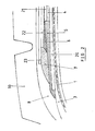
- the so-called protective ply (23) completes the crown reinforcement. Consisting of cables so-called elastic metals, i.e. having a force equal to 10% of the load rupture a relative elongation at least equal to 2%, making with the direction circumferential an angle equal to the angle made by the cables of the second layer of work (22), the ply (23) has a width equal to 335 mm, that is to say greater than L22 but less than L20. It is separated from the rubber cushion (5) by a second corner (7) of rubber mix having an extension modulus equal to the modulus of the layer (4) separating the ply (20) of circumferential cables from the first working ply (21) radially inner.
- the crown reinforcement (2) is topped with a layer (8) of low-rubbery mixture hysteresis, that is to say a hysteresis equal to half the hysteresis of the band rolling.
- Said layer (8) is itself radially surmounted by the strip of bearing (10).
Landscapes
- Engineering & Computer Science (AREA)
- Mechanical Engineering (AREA)
- Tires In General (AREA)
Description
- La figure 1 représente schématiquement, en section méridienne, la partie haute d'un pneumatique conforme à l'invention,
- La figure 2 étant un agrandissement de la partie cerclée de la figure 1.
Claims (2)
- Pneumatique, de rapport de forme H/S < 0,60, comprenant principalement une armature de carcasse composée d'au moins une nappe (1) de câbles radiaux, une armature de sommet (2) composée d'au moins deux nappes (21,22), dites de travail, de câbles métalliques inextensibles croisés et d'au moins une nappe (20) de câbles circonférentiels, disposée entre la nappe (1) de câbles radiaux la plus extérieure et la première nappe sommet de travail (21) radialement la plus à l'intérieur, ladite nappe de câbles circonférentiels (20) ayant des extrémités axialement au delà des extrémités des nappes de travail (21,22) et ladite armature de sommet (2) étant surmontée d'une bande de roulement (10) de largeur L, caractérisé en ce qu'est disposée, entre la nappe de câbles circonférentiels (20), de largeur L20 comprise entre 0,8 et 0,95 L, et la première nappe de travail (21) radialement la plus à l'intérieur, de largeur L21 comprise entre 0,5 et 0,7 L, une couche de mélange caoutchouteux (4) de faible module d'extension, d'épaisseur constante comprise entre 2 et 3 mm et ayant une largeur LM égale à L21, alors que la deuxième nappe de travail (22) radialement la plus à l'extérieur, de largeur axiale L22, supérieure à la largeur L21, est séparée radialement du bord de la nappe de câbles circonférentiels (20), d'une part par un coussin de caoutchouc (5) de fort module d'extension, s'étendant axialement de l'extrémité de la première nappe de travail (21) au delà de l'extrémité de la nappe de câbles circonférentiels (20), d'épaisseur pratiquement égale à l'épaisseur totale de la première nappe de travail (21) et de la couche de caoutchouc (4) à bas module, et d'autre part, radialement à l'extérieur dudit coussin (5), par un coin de caoutchouc (6) de module intermédiaire entre le bas module et le fort module et s'étendant axialement sensiblement du bord de la deuxième nappe de travail (22) à un point axialement à l'intérieur de l'extrémité de la première nappe de travail (21) d'une quantité comprise entre 0,03 et 0,10 fois la largeur L21, ledit coin (6) permettant le découplage des bords des nappes de travail (21) et (22).
- Pneumatique selon la revendication 1, caractérisé en ce que l'armature de sommet (2) est complétée par la présence, radialement au dessus de la deuxième nappe de travail (22) radialement la plus à l'extérieur, d'une nappe (23) de câbles élastiques orientés dans la même direction que celle des câbles de la deuxième nappe de travail sous-jacente (22), mais de largeur axiale L23 supérieure à L22 et inférieure à L20, ladite nappe de protection (23) étant alors séparée du coussin (5) par un coin de mélangé caoutchouteux (7) de bas module d'extension, identique au module de la couche caoutchouteuse (4), située entre la nappe de câbles circonférentiels (20) et la première nappe de travail (21) radialement la plus à l'intérieur.
Applications Claiming Priority (3)
| Application Number | Priority Date | Filing Date | Title |
|---|---|---|---|
| FR9613021 | 1996-10-23 | ||
| FR9613021A FR2754769B1 (fr) | 1996-10-23 | 1996-10-23 | Armature de sommet pour pneumatique "poids-lourds" de rapport de forme < 0,60 |
| PCT/EP1997/005625 WO1998017485A1 (fr) | 1996-10-23 | 1997-10-13 | Armature de sommet pour pneumatique 'poids-lourds' de rapport de forme ≤ 0,60 |
Publications (2)
| Publication Number | Publication Date |
|---|---|
| EP0885134A1 EP0885134A1 (fr) | 1998-12-23 |
| EP0885134B1 true EP0885134B1 (fr) | 2002-04-03 |
Family
ID=9497016
Family Applications (1)
| Application Number | Title | Priority Date | Filing Date |
|---|---|---|---|
| EP97910438A Expired - Lifetime EP0885134B1 (fr) | 1996-10-23 | 1997-10-13 | Armature de sommet pour pneumatique "poids-lourds" de rapport de forme 0,60 |
Country Status (10)
| Country | Link |
|---|---|
| US (1) | US5996662A (fr) |
| EP (1) | EP0885134B1 (fr) |
| JP (1) | JP4216339B2 (fr) |
| BR (1) | BR9706881A (fr) |
| CA (1) | CA2239793C (fr) |
| DE (1) | DE69711606T2 (fr) |
| ES (1) | ES2175364T3 (fr) |
| FR (1) | FR2754769B1 (fr) |
| MX (1) | MX9803727A (fr) |
| WO (1) | WO1998017485A1 (fr) |
Families Citing this family (30)
| Publication number | Priority date | Publication date | Assignee | Title |
|---|---|---|---|---|
| FR2784054A1 (fr) * | 1998-10-02 | 2000-04-07 | Michelin Soc Tech | Armature de sommet pour pneumatique radial |
| HU223234B1 (hu) * | 1999-05-14 | 2004-04-28 | Michelin Recherche Et Technique S.A. | Gumiabroncs radiális szövetváz-erősítéssel |
| JP2001213116A (ja) * | 2000-02-07 | 2001-08-07 | Bridgestone Corp | 空気入りタイヤ |
| US6371182B1 (en) * | 2000-02-24 | 2002-04-16 | The Goodyear Tire & Rubber Company | Runflat tire with dual-modulus underlay |
| US6622764B2 (en) * | 2002-02-01 | 2003-09-23 | The Goodyear Tire & Rubber Company | Underlay structure for increased crown stiffening |
| US6619357B1 (en) | 2002-04-24 | 2003-09-16 | The Goodyear Tire & Rubber Company | Belt package for super single truck tires |
| FR2857619B1 (fr) * | 2003-07-18 | 2005-08-19 | Michelin Soc Tech | Pneumatique pour vehicules lourds |
| FR2857620B1 (fr) * | 2003-07-18 | 2005-08-19 | Michelin Soc Tech | Pneumatique pour vehicules lourds |
| BRPI0412723B1 (pt) * | 2003-07-18 | 2013-12-24 | Michelin Rech Tech | Pneumático com armação de carcaça radial |
| US7267149B2 (en) * | 2003-12-22 | 2007-09-11 | The Goodyear Tire & Rubber Company | Pneumatic tire with improved crown durability |
| FR2887816A1 (fr) * | 2005-06-30 | 2007-01-05 | Michelin Soc Tech | Pneumatique pour vehicules lourds |
| JP4758764B2 (ja) * | 2005-12-28 | 2011-08-31 | 住友ゴム工業株式会社 | 重荷重用ラジアルタイヤ |
| FR2897557B1 (fr) * | 2006-02-21 | 2008-04-18 | Michelin Soc Tech | Pneumatique pour vehicules |
| JP4008013B1 (ja) * | 2006-06-23 | 2007-11-14 | 横浜ゴム株式会社 | 空気入りタイヤ |
| FR2907373B1 (fr) * | 2006-10-18 | 2009-01-16 | Michelin Soc Tech | Pneumatique pour engin lourd |
| FR2909311B1 (fr) * | 2006-12-04 | 2011-04-22 | Michelin Soc Tech | Pneumatique pour vehicule lourd. |
| FR2915131B1 (fr) * | 2007-04-23 | 2009-07-03 | Michelin Soc Tech | Pneumatique pour vehicule comportant des renforts dans les flancs |
| JP2009262826A (ja) * | 2008-04-25 | 2009-11-12 | Bridgestone Corp | 空気入りタイヤ |
| JP5330820B2 (ja) * | 2008-12-16 | 2013-10-30 | 株式会社ブリヂストン | 空気入りタイヤ |
| MX2011006013A (es) * | 2008-12-19 | 2011-06-28 | Michelin Rech Tech | Desempeño mejorado de hidroplaneo para una llanta. |
| JP5210334B2 (ja) * | 2010-02-05 | 2013-06-12 | 住友ゴム工業株式会社 | 重荷重用タイヤ |
| JP5694713B2 (ja) * | 2010-09-15 | 2015-04-01 | 株式会社ブリヂストン | 空気入りタイヤ |
| JP5836055B2 (ja) * | 2011-10-25 | 2015-12-24 | 株式会社ブリヂストン | 重荷重用空気入りラジアルタイヤ |
| JP5990384B2 (ja) * | 2012-02-21 | 2016-09-14 | 株式会社ブリヂストン | 空気入りタイヤ |
| JP5628946B2 (ja) * | 2013-02-12 | 2014-11-19 | 株式会社ブリヂストン | 重荷重用タイヤ |
| CN105829130A (zh) | 2013-12-24 | 2016-08-03 | 普利司通美国轮胎运营有限责任公司 | 具有环绕在胶条上的带束层的轮胎 |
| JP6514616B2 (ja) * | 2015-09-16 | 2019-05-15 | 住友ゴム工業株式会社 | 重荷重用タイヤ |
| FR3057810A1 (fr) * | 2016-10-21 | 2018-04-27 | Compagnie Generale Des Etablissements Michelin | Pneumatique a couches de travail comprenant une architecture optimisee |
| US10595191B1 (en) | 2018-12-06 | 2020-03-17 | At&T Intellectual Property I, L.P. | Mobility management enhancer |
| CN111674209B (zh) * | 2020-06-16 | 2022-05-17 | 江苏通用科技股份有限公司 | 一种全钢子午线轮胎带束层胎面复合件及其贴合工艺 |
Family Cites Families (11)
| Publication number | Priority date | Publication date | Assignee | Title |
|---|---|---|---|---|
| FR1290231A (fr) * | 1961-02-24 | 1962-04-13 | Kleber Colombes | Enveloppe de pneumatique |
| DE2313586A1 (de) * | 1973-03-19 | 1974-09-26 | Uniroyal Ag | Fahrzeugluftreifen, insbesondere fuer lastkraftwagen |
| FR2419185A1 (fr) * | 1978-03-10 | 1979-10-05 | Michelin & Cie | Pneumatique a carcasse radiale, notamment pour poids-lourds |
| US4262726A (en) * | 1978-06-16 | 1981-04-21 | The Goodyear Tire & Rubber Company | Radial tire with a low angle carcass overlay ply |
| DE3105209A1 (de) * | 1981-02-13 | 1982-09-09 | Continental Gummi-Werke Ag, 3000 Hannover | Fahrzeugluftreifen |
| JPS59124408A (ja) * | 1982-12-29 | 1984-07-18 | Bridgestone Corp | 重荷重用へん平空気入りラジアルタイヤの製法 |
| FR2566334B1 (fr) * | 1984-06-22 | 1987-02-13 | Bridgestone Corp | Pneumatique radial a faible section pour fortes charges et procede pour sa fabrication |
| DE3430501A1 (de) * | 1984-08-18 | 1986-03-13 | Continental Gummi-Werke Ag, 3000 Hannover | Fahrzeugluftreifen |
| EP0192910B2 (fr) * | 1985-02-26 | 1993-08-25 | The Goodyear Tire & Rubber Company | Bandage pneumatique |
| DE3802503A1 (de) * | 1988-01-28 | 1989-08-10 | Continental Ag | Fahrzeugluftreifen |
| JPH04183606A (ja) * | 1990-11-16 | 1992-06-30 | Yokohama Rubber Co Ltd:The | 空気入りラジアルタイヤ |
-
1996
- 1996-10-23 FR FR9613021A patent/FR2754769B1/fr not_active Expired - Fee Related
-
1997
- 1997-10-13 JP JP51890798A patent/JP4216339B2/ja not_active Expired - Fee Related
- 1997-10-13 CA CA002239793A patent/CA2239793C/fr not_active Expired - Fee Related
- 1997-10-13 BR BR9706881-0A patent/BR9706881A/pt not_active IP Right Cessation
- 1997-10-13 WO PCT/EP1997/005625 patent/WO1998017485A1/fr active IP Right Grant
- 1997-10-13 EP EP97910438A patent/EP0885134B1/fr not_active Expired - Lifetime
- 1997-10-13 ES ES97910438T patent/ES2175364T3/es not_active Expired - Lifetime
- 1997-10-13 US US09/077,857 patent/US5996662A/en not_active Expired - Lifetime
- 1997-10-13 DE DE69711606T patent/DE69711606T2/de not_active Expired - Lifetime
-
1998
- 1998-05-11 MX MX9803727A patent/MX9803727A/es unknown
Also Published As
| Publication number | Publication date |
|---|---|
| JP2000502307A (ja) | 2000-02-29 |
| WO1998017485A1 (fr) | 1998-04-30 |
| JP4216339B2 (ja) | 2009-01-28 |
| EP0885134A1 (fr) | 1998-12-23 |
| BR9706881A (pt) | 2000-01-25 |
| DE69711606D1 (de) | 2002-05-08 |
| CA2239793C (fr) | 2005-09-20 |
| FR2754769A1 (fr) | 1998-04-24 |
| CA2239793A1 (fr) | 1998-04-30 |
| ES2175364T3 (es) | 2002-11-16 |
| DE69711606T2 (de) | 2002-10-31 |
| FR2754769B1 (fr) | 1998-12-11 |
| US5996662A (en) | 1999-12-07 |
| MX9803727A (es) | 1998-09-30 |
Similar Documents
| Publication | Publication Date | Title |
|---|---|---|
| EP0885134B1 (fr) | Armature de sommet pour pneumatique "poids-lourds" de rapport de forme 0,60 | |
| EP0963301B1 (fr) | Pneumatique de rapport de forme h/s inferieur ou egal a 0,6 | |
| CA2208561C (fr) | Pneumatique de rapport de forme h/s <= 0,6 | |
| EP0883503B1 (fr) | Armature de sommet, particulierement pour pneumatique "poids-lourds" | |
| CA2308037C (fr) | Armature de sommet pour pneumatique "poids-lourds" | |
| EP1062106B1 (fr) | Pneumatique a armature de sommet triangulee | |
| CA2334098A1 (fr) | Bourrelet renforce de pneumatique radial | |
| FR2857621A1 (fr) | Pneumatique pour vehicules lourds | |
| WO1996025297A1 (fr) | Armature de sommet pour pneumatique radial | |
| EP0539436B1 (fr) | Pneumatique dont les bourrelets a sieges tronconiques sont munis d'au moins une tringle principale et d'une tringle auxiliaire | |
| CA2247086C (fr) | Armature de sommet de pneumatique | |
| EP1077815B1 (fr) | Armature de sommet de pneumatique radial | |
| EP1899178B1 (fr) | Pneumatique pour vehicules lourds | |
| FR3050962A1 (fr) | Pneumatique dont la zone du bourrelet est allegee | |
| FR2775218A1 (fr) | Armature de sommet pour pneumatique a rapport de forme h/s inferieur a o,65 | |
| WO2000054992A1 (fr) | Pneumatique pour engin lourd | |
| EP1077814B1 (fr) | Armature de sommet de pneumatique | |
| FR3050961A1 (fr) | Pneumatique dont la zone du bourrelet est allegee |
Legal Events
| Date | Code | Title | Description |
|---|---|---|---|
| PUAI | Public reference made under article 153(3) epc to a published international application that has entered the european phase |
Free format text: ORIGINAL CODE: 0009012 |
|
| AK | Designated contracting states |
Kind code of ref document: A1 Designated state(s): DE ES FI FR GB IT |
|
| 17P | Request for examination filed |
Effective date: 19981030 |
|
| GRAG | Despatch of communication of intention to grant |
Free format text: ORIGINAL CODE: EPIDOS AGRA |
|
| RTI1 | Title (correction) |
Free format text: BREAKER FOR HEAVY ROAD VEHICLE TYRE WITH FORM RATIO 0.60 |
|
| 17Q | First examination report despatched |
Effective date: 20001124 |
|
| GRAG | Despatch of communication of intention to grant |
Free format text: ORIGINAL CODE: EPIDOS AGRA |
|
| GRAG | Despatch of communication of intention to grant |
Free format text: ORIGINAL CODE: EPIDOS AGRA |
|
| GRAH | Despatch of communication of intention to grant a patent |
Free format text: ORIGINAL CODE: EPIDOS IGRA |
|
| REG | Reference to a national code |
Ref country code: GB Ref legal event code: IF02 |
|
| GRAH | Despatch of communication of intention to grant a patent |
Free format text: ORIGINAL CODE: EPIDOS IGRA |
|
| GRAA | (expected) grant |
Free format text: ORIGINAL CODE: 0009210 |
|
| AK | Designated contracting states |
Kind code of ref document: B1 Designated state(s): DE ES FI FR GB IT |
|
| REF | Corresponds to: |
Ref document number: 69711606 Country of ref document: DE Date of ref document: 20020508 |
|
| GBT | Gb: translation of ep patent filed (gb section 77(6)(a)/1977) |
Effective date: 20020625 |
|
| REG | Reference to a national code |
Ref country code: ES Ref legal event code: FG2A Ref document number: 2175364 Country of ref document: ES Kind code of ref document: T3 |
|
| PLBE | No opposition filed within time limit |
Free format text: ORIGINAL CODE: 0009261 |
|
| STAA | Information on the status of an ep patent application or granted ep patent |
Free format text: STATUS: NO OPPOSITION FILED WITHIN TIME LIMIT |
|
| 26N | No opposition filed |
Effective date: 20030106 |
|
| PGFP | Annual fee paid to national office [announced via postgrant information from national office to epo] |
Ref country code: GB Payment date: 20071023 Year of fee payment: 11 |
|
| GBPC | Gb: european patent ceased through non-payment of renewal fee |
Effective date: 20081013 |
|
| PG25 | Lapsed in a contracting state [announced via postgrant information from national office to epo] |
Ref country code: GB Free format text: LAPSE BECAUSE OF NON-PAYMENT OF DUE FEES Effective date: 20081013 |
|
| PGFP | Annual fee paid to national office [announced via postgrant information from national office to epo] |
Ref country code: FI Payment date: 20101014 Year of fee payment: 14 |
|
| PG25 | Lapsed in a contracting state [announced via postgrant information from national office to epo] |
Ref country code: FI Free format text: LAPSE BECAUSE OF NON-PAYMENT OF DUE FEES Effective date: 20111013 |
|
| PGFP | Annual fee paid to national office [announced via postgrant information from national office to epo] |
Ref country code: ES Payment date: 20121026 Year of fee payment: 16 Ref country code: IT Payment date: 20121022 Year of fee payment: 16 |
|
| PG25 | Lapsed in a contracting state [announced via postgrant information from national office to epo] |
Ref country code: IT Free format text: LAPSE BECAUSE OF NON-PAYMENT OF DUE FEES Effective date: 20131013 |
|
| REG | Reference to a national code |
Ref country code: ES Ref legal event code: FD2A Effective date: 20141107 |
|
| PG25 | Lapsed in a contracting state [announced via postgrant information from national office to epo] |
Ref country code: ES Free format text: LAPSE BECAUSE OF NON-PAYMENT OF DUE FEES Effective date: 20131014 |
|
| REG | Reference to a national code |
Ref country code: FR Ref legal event code: PLFP Year of fee payment: 19 |
|
| PGFP | Annual fee paid to national office [announced via postgrant information from national office to epo] |
Ref country code: DE Payment date: 20151022 Year of fee payment: 19 |
|
| PGFP | Annual fee paid to national office [announced via postgrant information from national office to epo] |
Ref country code: FR Payment date: 20151023 Year of fee payment: 19 |
|
| REG | Reference to a national code |
Ref country code: DE Ref legal event code: R119 Ref document number: 69711606 Country of ref document: DE |
|
| REG | Reference to a national code |
Ref country code: FR Ref legal event code: ST Effective date: 20170630 |
|
| PG25 | Lapsed in a contracting state [announced via postgrant information from national office to epo] |
Ref country code: DE Free format text: LAPSE BECAUSE OF NON-PAYMENT OF DUE FEES Effective date: 20170503 Ref country code: FR Free format text: LAPSE BECAUSE OF NON-PAYMENT OF DUE FEES Effective date: 20161102 |