EP0884482B1 - Dispositif de commande pour machine hydraulique d'entrainement - Google Patents
Dispositif de commande pour machine hydraulique d'entrainement Download PDFInfo
- Publication number
- EP0884482B1 EP0884482B1 EP97903627A EP97903627A EP0884482B1 EP 0884482 B1 EP0884482 B1 EP 0884482B1 EP 97903627 A EP97903627 A EP 97903627A EP 97903627 A EP97903627 A EP 97903627A EP 0884482 B1 EP0884482 B1 EP 0884482B1
- Authority
- EP
- European Patent Office
- Prior art keywords
- pressure
- differential pressure
- hydraulic
- control
- operating
- Prior art date
- Legal status (The legal status is an assumption and is not a legal conclusion. Google has not performed a legal analysis and makes no representation as to the accuracy of the status listed.)
- Expired - Lifetime
Links
Images


Classifications
-
- F—MECHANICAL ENGINEERING; LIGHTING; HEATING; WEAPONS; BLASTING
- F15—FLUID-PRESSURE ACTUATORS; HYDRAULICS OR PNEUMATICS IN GENERAL
- F15B—SYSTEMS ACTING BY MEANS OF FLUIDS IN GENERAL; FLUID-PRESSURE ACTUATORS, e.g. SERVOMOTORS; DETAILS OF FLUID-PRESSURE SYSTEMS, NOT OTHERWISE PROVIDED FOR
- F15B11/00—Servomotor systems without provision for follow-up action; Circuits therefor
- F15B11/16—Servomotor systems without provision for follow-up action; Circuits therefor with two or more servomotors
- F15B11/161—Servomotor systems without provision for follow-up action; Circuits therefor with two or more servomotors with sensing of servomotor demand or load
- F15B11/163—Servomotor systems without provision for follow-up action; Circuits therefor with two or more servomotors with sensing of servomotor demand or load for sharing the pump output equally amongst users or groups of users, e.g. using anti-saturation, pressure compensation
-
- B—PERFORMING OPERATIONS; TRANSPORTING
- B60—VEHICLES IN GENERAL
- B60R—VEHICLES, VEHICLE FITTINGS, OR VEHICLE PARTS, NOT OTHERWISE PROVIDED FOR
- B60R16/00—Electric or fluid circuits specially adapted for vehicles and not otherwise provided for; Arrangement of elements of electric or fluid circuits specially adapted for vehicles and not otherwise provided for
- B60R16/02—Electric or fluid circuits specially adapted for vehicles and not otherwise provided for; Arrangement of elements of electric or fluid circuits specially adapted for vehicles and not otherwise provided for electric constitutive elements
- B60R16/03—Electric or fluid circuits specially adapted for vehicles and not otherwise provided for; Arrangement of elements of electric or fluid circuits specially adapted for vehicles and not otherwise provided for electric constitutive elements for supply of electrical power to vehicle subsystems or for
- B60R16/0315—Electric or fluid circuits specially adapted for vehicles and not otherwise provided for; Arrangement of elements of electric or fluid circuits specially adapted for vehicles and not otherwise provided for electric constitutive elements for supply of electrical power to vehicle subsystems or for using multiplexing techniques
-
- F—MECHANICAL ENGINEERING; LIGHTING; HEATING; WEAPONS; BLASTING
- F15—FLUID-PRESSURE ACTUATORS; HYDRAULICS OR PNEUMATICS IN GENERAL
- F15B—SYSTEMS ACTING BY MEANS OF FLUIDS IN GENERAL; FLUID-PRESSURE ACTUATORS, e.g. SERVOMOTORS; DETAILS OF FLUID-PRESSURE SYSTEMS, NOT OTHERWISE PROVIDED FOR
- F15B11/00—Servomotor systems without provision for follow-up action; Circuits therefor
- F15B11/16—Servomotor systems without provision for follow-up action; Circuits therefor with two or more servomotors
- F15B11/161—Servomotor systems without provision for follow-up action; Circuits therefor with two or more servomotors with sensing of servomotor demand or load
- F15B11/166—Controlling a pilot pressure in response to the load, i.e. supply to at least one user is regulated by adjusting either the system pilot pressure or one or more of the individual pilot command pressures
-
- F—MECHANICAL ENGINEERING; LIGHTING; HEATING; WEAPONS; BLASTING
- F15—FLUID-PRESSURE ACTUATORS; HYDRAULICS OR PNEUMATICS IN GENERAL
- F15B—SYSTEMS ACTING BY MEANS OF FLUIDS IN GENERAL; FLUID-PRESSURE ACTUATORS, e.g. SERVOMOTORS; DETAILS OF FLUID-PRESSURE SYSTEMS, NOT OTHERWISE PROVIDED FOR
- F15B21/00—Common features of fluid actuator systems; Fluid-pressure actuator systems or details thereof, not covered by any other group of this subclass
- F15B21/08—Servomotor systems incorporating electrically operated control means
- F15B21/087—Control strategy, e.g. with block diagram
-
- B—PERFORMING OPERATIONS; TRANSPORTING
- B60—VEHICLES IN GENERAL
- B60R—VEHICLES, VEHICLE FITTINGS, OR VEHICLE PARTS, NOT OTHERWISE PROVIDED FOR
- B60R16/00—Electric or fluid circuits specially adapted for vehicles and not otherwise provided for; Arrangement of elements of electric or fluid circuits specially adapted for vehicles and not otherwise provided for
- B60R16/02—Electric or fluid circuits specially adapted for vehicles and not otherwise provided for; Arrangement of elements of electric or fluid circuits specially adapted for vehicles and not otherwise provided for electric constitutive elements
- B60R16/03—Electric or fluid circuits specially adapted for vehicles and not otherwise provided for; Arrangement of elements of electric or fluid circuits specially adapted for vehicles and not otherwise provided for electric constitutive elements for supply of electrical power to vehicle subsystems or for
- B60R16/0315—Electric or fluid circuits specially adapted for vehicles and not otherwise provided for; Arrangement of elements of electric or fluid circuits specially adapted for vehicles and not otherwise provided for electric constitutive elements for supply of electrical power to vehicle subsystems or for using multiplexing techniques
- B60R2016/0322—Temporary code for documents to be reclassified to G08C, H04L or H04Q
-
- F—MECHANICAL ENGINEERING; LIGHTING; HEATING; WEAPONS; BLASTING
- F15—FLUID-PRESSURE ACTUATORS; HYDRAULICS OR PNEUMATICS IN GENERAL
- F15B—SYSTEMS ACTING BY MEANS OF FLUIDS IN GENERAL; FLUID-PRESSURE ACTUATORS, e.g. SERVOMOTORS; DETAILS OF FLUID-PRESSURE SYSTEMS, NOT OTHERWISE PROVIDED FOR
- F15B2211/00—Circuits for servomotor systems
- F15B2211/20—Fluid pressure source, e.g. accumulator or variable axial piston pump
- F15B2211/205—Systems with pumps
- F15B2211/2053—Type of pump
- F15B2211/20546—Type of pump variable capacity
- F15B2211/20553—Type of pump variable capacity with pilot circuit, e.g. for controlling a swash plate
-
- F—MECHANICAL ENGINEERING; LIGHTING; HEATING; WEAPONS; BLASTING
- F15—FLUID-PRESSURE ACTUATORS; HYDRAULICS OR PNEUMATICS IN GENERAL
- F15B—SYSTEMS ACTING BY MEANS OF FLUIDS IN GENERAL; FLUID-PRESSURE ACTUATORS, e.g. SERVOMOTORS; DETAILS OF FLUID-PRESSURE SYSTEMS, NOT OTHERWISE PROVIDED FOR
- F15B2211/00—Circuits for servomotor systems
- F15B2211/30—Directional control
- F15B2211/31—Directional control characterised by the positions of the valve element
- F15B2211/3105—Neutral or centre positions
- F15B2211/3111—Neutral or centre positions the pump port being closed in the centre position, e.g. so-called closed centre
-
- F—MECHANICAL ENGINEERING; LIGHTING; HEATING; WEAPONS; BLASTING
- F15—FLUID-PRESSURE ACTUATORS; HYDRAULICS OR PNEUMATICS IN GENERAL
- F15B—SYSTEMS ACTING BY MEANS OF FLUIDS IN GENERAL; FLUID-PRESSURE ACTUATORS, e.g. SERVOMOTORS; DETAILS OF FLUID-PRESSURE SYSTEMS, NOT OTHERWISE PROVIDED FOR
- F15B2211/00—Circuits for servomotor systems
- F15B2211/30—Directional control
- F15B2211/32—Directional control characterised by the type of actuation
- F15B2211/327—Directional control characterised by the type of actuation electrically or electronically
-
- F—MECHANICAL ENGINEERING; LIGHTING; HEATING; WEAPONS; BLASTING
- F15—FLUID-PRESSURE ACTUATORS; HYDRAULICS OR PNEUMATICS IN GENERAL
- F15B—SYSTEMS ACTING BY MEANS OF FLUIDS IN GENERAL; FLUID-PRESSURE ACTUATORS, e.g. SERVOMOTORS; DETAILS OF FLUID-PRESSURE SYSTEMS, NOT OTHERWISE PROVIDED FOR
- F15B2211/00—Circuits for servomotor systems
- F15B2211/60—Circuit components or control therefor
- F15B2211/63—Electronic controllers
- F15B2211/6303—Electronic controllers using input signals
- F15B2211/6306—Electronic controllers using input signals representing a pressure
- F15B2211/6309—Electronic controllers using input signals representing a pressure the pressure being a pressure source supply pressure
-
- F—MECHANICAL ENGINEERING; LIGHTING; HEATING; WEAPONS; BLASTING
- F15—FLUID-PRESSURE ACTUATORS; HYDRAULICS OR PNEUMATICS IN GENERAL
- F15B—SYSTEMS ACTING BY MEANS OF FLUIDS IN GENERAL; FLUID-PRESSURE ACTUATORS, e.g. SERVOMOTORS; DETAILS OF FLUID-PRESSURE SYSTEMS, NOT OTHERWISE PROVIDED FOR
- F15B2211/00—Circuits for servomotor systems
- F15B2211/60—Circuit components or control therefor
- F15B2211/63—Electronic controllers
- F15B2211/6303—Electronic controllers using input signals
- F15B2211/6306—Electronic controllers using input signals representing a pressure
- F15B2211/6313—Electronic controllers using input signals representing a pressure the pressure being a load pressure
-
- F—MECHANICAL ENGINEERING; LIGHTING; HEATING; WEAPONS; BLASTING
- F15—FLUID-PRESSURE ACTUATORS; HYDRAULICS OR PNEUMATICS IN GENERAL
- F15B—SYSTEMS ACTING BY MEANS OF FLUIDS IN GENERAL; FLUID-PRESSURE ACTUATORS, e.g. SERVOMOTORS; DETAILS OF FLUID-PRESSURE SYSTEMS, NOT OTHERWISE PROVIDED FOR
- F15B2211/00—Circuits for servomotor systems
- F15B2211/60—Circuit components or control therefor
- F15B2211/63—Electronic controllers
- F15B2211/6303—Electronic controllers using input signals
- F15B2211/633—Electronic controllers using input signals representing a state of the prime mover, e.g. torque or rotational speed
-
- F—MECHANICAL ENGINEERING; LIGHTING; HEATING; WEAPONS; BLASTING
- F15—FLUID-PRESSURE ACTUATORS; HYDRAULICS OR PNEUMATICS IN GENERAL
- F15B—SYSTEMS ACTING BY MEANS OF FLUIDS IN GENERAL; FLUID-PRESSURE ACTUATORS, e.g. SERVOMOTORS; DETAILS OF FLUID-PRESSURE SYSTEMS, NOT OTHERWISE PROVIDED FOR
- F15B2211/00—Circuits for servomotor systems
- F15B2211/60—Circuit components or control therefor
- F15B2211/63—Electronic controllers
- F15B2211/6303—Electronic controllers using input signals
- F15B2211/6346—Electronic controllers using input signals representing a state of input means, e.g. joystick position
-
- F—MECHANICAL ENGINEERING; LIGHTING; HEATING; WEAPONS; BLASTING
- F15—FLUID-PRESSURE ACTUATORS; HYDRAULICS OR PNEUMATICS IN GENERAL
- F15B—SYSTEMS ACTING BY MEANS OF FLUIDS IN GENERAL; FLUID-PRESSURE ACTUATORS, e.g. SERVOMOTORS; DETAILS OF FLUID-PRESSURE SYSTEMS, NOT OTHERWISE PROVIDED FOR
- F15B2211/00—Circuits for servomotor systems
- F15B2211/60—Circuit components or control therefor
- F15B2211/665—Methods of control using electronic components
- F15B2211/6651—Control of the prime mover, e.g. control of the output torque or rotational speed
-
- F—MECHANICAL ENGINEERING; LIGHTING; HEATING; WEAPONS; BLASTING
- F15—FLUID-PRESSURE ACTUATORS; HYDRAULICS OR PNEUMATICS IN GENERAL
- F15B—SYSTEMS ACTING BY MEANS OF FLUIDS IN GENERAL; FLUID-PRESSURE ACTUATORS, e.g. SERVOMOTORS; DETAILS OF FLUID-PRESSURE SYSTEMS, NOT OTHERWISE PROVIDED FOR
- F15B2211/00—Circuits for servomotor systems
- F15B2211/60—Circuit components or control therefor
- F15B2211/665—Methods of control using electronic components
- F15B2211/6652—Control of the pressure source, e.g. control of the swash plate angle
-
- F—MECHANICAL ENGINEERING; LIGHTING; HEATING; WEAPONS; BLASTING
- F15—FLUID-PRESSURE ACTUATORS; HYDRAULICS OR PNEUMATICS IN GENERAL
- F15B—SYSTEMS ACTING BY MEANS OF FLUIDS IN GENERAL; FLUID-PRESSURE ACTUATORS, e.g. SERVOMOTORS; DETAILS OF FLUID-PRESSURE SYSTEMS, NOT OTHERWISE PROVIDED FOR
- F15B2211/00—Circuits for servomotor systems
- F15B2211/60—Circuit components or control therefor
- F15B2211/665—Methods of control using electronic components
- F15B2211/6654—Flow rate control
-
- F—MECHANICAL ENGINEERING; LIGHTING; HEATING; WEAPONS; BLASTING
- F15—FLUID-PRESSURE ACTUATORS; HYDRAULICS OR PNEUMATICS IN GENERAL
- F15B—SYSTEMS ACTING BY MEANS OF FLUIDS IN GENERAL; FLUID-PRESSURE ACTUATORS, e.g. SERVOMOTORS; DETAILS OF FLUID-PRESSURE SYSTEMS, NOT OTHERWISE PROVIDED FOR
- F15B2211/00—Circuits for servomotor systems
- F15B2211/60—Circuit components or control therefor
- F15B2211/67—Methods for controlling pilot pressure
-
- F—MECHANICAL ENGINEERING; LIGHTING; HEATING; WEAPONS; BLASTING
- F15—FLUID-PRESSURE ACTUATORS; HYDRAULICS OR PNEUMATICS IN GENERAL
- F15B—SYSTEMS ACTING BY MEANS OF FLUIDS IN GENERAL; FLUID-PRESSURE ACTUATORS, e.g. SERVOMOTORS; DETAILS OF FLUID-PRESSURE SYSTEMS, NOT OTHERWISE PROVIDED FOR
- F15B2211/00—Circuits for servomotor systems
- F15B2211/70—Output members, e.g. hydraulic motors or cylinders or control therefor
- F15B2211/705—Output members, e.g. hydraulic motors or cylinders or control therefor characterised by the type of output members or actuators
- F15B2211/7051—Linear output members
- F15B2211/7053—Double-acting output members
-
- F—MECHANICAL ENGINEERING; LIGHTING; HEATING; WEAPONS; BLASTING
- F15—FLUID-PRESSURE ACTUATORS; HYDRAULICS OR PNEUMATICS IN GENERAL
- F15B—SYSTEMS ACTING BY MEANS OF FLUIDS IN GENERAL; FLUID-PRESSURE ACTUATORS, e.g. SERVOMOTORS; DETAILS OF FLUID-PRESSURE SYSTEMS, NOT OTHERWISE PROVIDED FOR
- F15B2211/00—Circuits for servomotor systems
- F15B2211/70—Output members, e.g. hydraulic motors or cylinders or control therefor
- F15B2211/71—Multiple output members, e.g. multiple hydraulic motors or cylinders
-
- F—MECHANICAL ENGINEERING; LIGHTING; HEATING; WEAPONS; BLASTING
- F15—FLUID-PRESSURE ACTUATORS; HYDRAULICS OR PNEUMATICS IN GENERAL
- F15B—SYSTEMS ACTING BY MEANS OF FLUIDS IN GENERAL; FLUID-PRESSURE ACTUATORS, e.g. SERVOMOTORS; DETAILS OF FLUID-PRESSURE SYSTEMS, NOT OTHERWISE PROVIDED FOR
- F15B2211/00—Circuits for servomotor systems
- F15B2211/70—Output members, e.g. hydraulic motors or cylinders or control therefor
- F15B2211/75—Control of speed of the output member
-
- F—MECHANICAL ENGINEERING; LIGHTING; HEATING; WEAPONS; BLASTING
- F15—FLUID-PRESSURE ACTUATORS; HYDRAULICS OR PNEUMATICS IN GENERAL
- F15B—SYSTEMS ACTING BY MEANS OF FLUIDS IN GENERAL; FLUID-PRESSURE ACTUATORS, e.g. SERVOMOTORS; DETAILS OF FLUID-PRESSURE SYSTEMS, NOT OTHERWISE PROVIDED FOR
- F15B2211/00—Circuits for servomotor systems
- F15B2211/70—Output members, e.g. hydraulic motors or cylinders or control therefor
- F15B2211/78—Control of multiple output members
Definitions
- the present invention relates to a control device, which drives and controls a hydraulic actuator in accordance with the control input of an operating member in a hydraulic drive machine, such as a hydraulic excavator, or crane.
- hydraulic drive machines such as construction equipment, are configured so that a drive command signal, which specifies a control input for a plurality of operating levers, is applied to a plurality of corresponding operating valves (flow control valves).
- the above drive command signal changes the areas of the apertures of these plurality of operating valves, thereby driving a corresponding plurality of hydraulic actuators.
- pressure oil discharged by a hydraulic pump is supplied to a plurality of hydraulic actuators via a plurality of operating valves on a plurality of pressure oil supply channels, and these plurality of hydraulic actuators are driven simultaneously.
- a valve called a pressure compensation valve, is provided either between a hydraulic pump and a flow control valve, or between a flow control valve and a hydraulic actuator, and works to compensate for the differential pressure of pressure across a valve for pressure oil, which flows through a flow control valve, so that this differential pressure is the same value for all drive shafts (In construction equipment, a drive shaft refers to a boom, arm, et cetera.).
- the load sensing system works to control the discharge pressure of the hydraulic pump so that the discharge pressure of the hydraulic pump achieves a pressure whereby the above across-valve differential pressure is added to the maximum value of the load of the operating hydraulic actuators. This prevents changes in velocity (load dependency) resulting from differences in the load of each hydraulic actuator when operated in combination.
- Japanese Patent Publication No. 6-41762 and Japanese Patent Publication No. 6-41764 propose the configuration of a system that does not utilize the above-mentioned pressure compensation valve.
- the square root of the ratio between a differential pressure set in advance and the detected value of the differential pressure across a flow control valve is used as the correction factor to compensate for the drive command value (control input from operating lever) for pertinent flow control valves of drive shafts other than the drive shaft with a minimum differential pressure across the flow control valve.
- pump load sensing control is essential so that the differential pressure between the discharge pressure of the hydraulic pump and the maximum load pressure of the plurality of hydraulic actuators (minimum differential pressure) becomes the differential pressure that was set in advance.
- mini differential pressure the differential pressure between the discharge pressure of the hydraulic pump and the maximum load pressure of the plurality of hydraulic actuators.
- the idea is to digitize a conventional load sensing system as-is, and to deal with a small differential pressure by shutting off control.
- the invention of the present application takes these facts into consideration, and has as a first object to make do with a simple hydraulic circuit, which does not utilize a pressure compensation valve, and to enable the use of an inexpensive, low precision pressure detector, to enable the maintenance of continuous control at all times using simple controls, and to get by without shocking the operator or the mechanical parts, and to cancel the load dependency of a hydraulic actuator flow during combined operation without limiting the control system of the hydraulic pump.
- an operation performed frequently during hydraulic excavator work is "rough-combing" whereby the surface of the ground is leveled.
- an operator prefers to move the cutting edge of the bucket roughly horizontally over the surface of the ground using a full-lever boom-up, arm-excavation operation. If there is no pressure compensation at this point, because there is little pressure for raising the boom, the cutting edge of the bucket moves roughly horizontally over the ground. But when all-out pressure compensation is applied, it gives rise to the problem of the trajectory of the cutting edge of the bucket rising high into a circular arc.
- the present invention takes this fact into consideration, and has as a second object enhancing lever controllability, and improving work efficiency by making it possible to change pressure compensation characteristics of a hydraulic actuator in accordance with operating lever operating status and load pressure.
- an embodiment of the present invention is a control device for a hydraulic drive machine which comprises a hydraulic pump, a plurality of hydraulic actuators provided in correspondence with a plurality of operating members, and a plurality of operating valves for supplying to corresponding hydraulic actuators a pressure oil discharged from the hydraulic pump at a flow rate that accords with control inputs of the operating members, and which drives the hydraulic actuators in accordance with the operation of the operating members, where the control device comprises,
- a correction factor for correcting the control input of an operating member that corresponds to this operating valve is calculated for each operating member on the basis of the ratio between the detected differential pressure across an operating valve and a minimum differential pressure selected from among the differential pressures across a plurality of operating valves. And the control input of a corresponding operating member is corrected using this calculated correction factor.
- the flow Qi supplied to the ith hydraulic actuator is determined solely by the size of the aperture area command value Ai.
- the numerator when division is performed using a number near zero (when the detected differential pressure is the minimum differential pressure), the numerator is also the minimum differential pressure, so the quotient is always 1, and errors contained in a detection error offset one another. Conversely, even when division is performed using a detected differential pressure other than the minimum differential pressure, because the detected differential pressure denominator is larger than the minimum differential pressure numerator, the process is completed with little impact from detection errors. That is, because better-than-constant precision can be ensured even using an inexpensive, low-precision pressure detector, cost reducing effects can be achieved.
- control is performed using a compensation calculation that divides the minimum differential pressure by the detected pressure ⁇ P at each operating valve without having to switch from compensation calculation-based control to ordinary control each time there is a switchover to a drive shaft with the minimum across-valve differential pressure.
- the drive command values to a hydraulic actuator are continuous during the instant of control switchover, thus solving for the past problem of a shock being generated at each switchover. This achieves the effect whereby control continuity can be maintained via simple control, and the operator and machine parts are not shocked.
- a second embodiment not forming a part of the claimed invention is a control device for a hydraulic drive machine which comprises a hydraulic pump, a plurality of hydraulic actuators provided in correspondence with a plurality of operating members, and a plurality of operating valves for supplying to corresponding hydraulic actuators a pressure oil discharged from the hydraulic pump at a flow rate that accords with control inputs of the operating members, and which drives the hydraulic actuators in accordance with the operation of the operating members, where the control device comprises:
- an upper limit value or lower limit value of the correction factor is set for each operating member in accordance with the control input of the operating member, making it so that a correction factor obtained in accordance with a detected differential pressure does not exceed the above-mentioned set upper limit value of lower limit value, and the control input of a corresponding operating member is corrected using a correction factor, which is limited by this upper limit or lower limit.
- the pressure compensation function is weakened, and the large incoming flow to a hydraulic actuator with a light load is not controlled.
- the present invention improves controllability at full-lever operation, and work efficiency is enhanced pursuant thereto.
- the hydraulic drive machine in this embodiment presupposes construction equipment such as a hydraulic excavator.
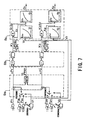
- Fig. 1 shows a configuration of a control device for a hydraulic excavator.
- this device comprises a variable capacity hydraulic pump 1, which is driven by an engine not depicted in the figure, the swash plate inclined rotation angle of which is changed in accordance with a drive command outputted from a controller 8, and the discharge flow of which is changed in accordance thereto; 2 hydraulic cylinders 2, 3 as hydraulic actuators, which are provided corresponding to each of 2 operating levers 6, 7 as operating members; 2 flow control valves 4, 5 as operating valves, which are provided on each of 2 pressure oil supply channels 31, 32 between the hydraulic pump 1 and the above-mentioned hydraulic cylinders 2, 3, and the aperture areas thereof are changed in accordance with drive commands S1, S2 outputted from the controller 8, and which supply to the hydraulic cylinders 2, 3 corresponding thereto a flow of pressure oil corresponding to these changed aperture areas; and a controller 8, which, as described below, performs correction and other processing of control inputs V1, V2 for the above-mentioned operating levers 6, 7, outputs to the flow control valves 4, 5 corresponding thereto drive control signals S1, S
- operating lever 6 is an electric lever for driving a boom (connected to hydraulic cylinder 2), which is a working machine not shown in the figure, and this electric lever outputs an electric signal, which is proportional to the operator-manipulated input.
- operating lever 7 is an electric lever for driving an arm (connected to hydraulic cylinder 3), which is a working machine not shown in the figure, and this electric lever outputs an electric signal, which is proportional to the operator-manipulated input.
- a pressure sensor 9 which detects the discharge pressure Pp of the hydraulic pump 1, is positioned on a pressure oil supply channel 30, which bifurcates to the above-mentioned pressure oil supply channels 31, 32.
- pressure sensors 10a, 10b which detect boom load pressures P1B, P1H, are positioned along pressure oil supply channel 31 on the supply channel that runs through the bottom chamber of hydraulic cylinder 2, and on the supply channel that runs through the head chamber of hydraulic cylinder 2, respectively.
- pressure sensors 11a, 11b which detect arm load pressures P1B, P1H, are positioned along pressure oil supply channel 32 on the supply channel that runs through the bottom chamber of hydraulic cylinder 3, and on the supply channel that runs through the head chamber of hydraulic cylinder 3, respectively.
- the detection signals of each of these pressure sensors are inputted to the controller 8 together with electric signals, which specify the control input of the above-mentioned operating levers 6, 7, and the processing illustrated in Fig. 2 is implemented.
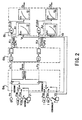
- Fig. 2 is a block diagram illustrating the arithmetic processing performed by the controller 8. Also, to expedite the explanation, the arithmetic processing is illustrated as it is performed by each processor, but of course, the system can also be designed so that all processing is performed by software.
- P1B the bottom chamber side, which is the side from which pressure oil flows into hydraulic cylinder 2
- P2H the head chamber side, which is the side from which pressure oil flows into hydraulic cylinder 3
- correction factors K1, K2 are inputted into drive command value correction means 8c, together with the drive command value control inputs V1, V2 from the operating levers 6, 7.
- the aperture area A1 relative to current control input V1 is determined on the basis of the relationship between a pre-set operating stroke volume (the spool stroke volume of flow control valve 4) V1, and the spool aperture area A1 of flow control valve 4.
- the aperture area A2 relative to current control input V2 is determined in a similar manner.
- the relationship of the above-mentioned spool stroke aperture area is univocally determined by the shape of the spool.
- spool stroke volumes S1, S2 corresponding to the above-mentioned corrected aperture areas A1', A2' are determined via the inverse relationship of the above-mentioned pre-set spool stroke aperture area, and the signal that specifies this spool stroke volume S1, S2 is applied to the respective solenoids of electromagnetic proportional pilot valve 12, which drives the main spool of the boom flow control valve 4, and electromagnetic proportional pilot valve 13, which drives the main spool of the arm flow control valve 5.
- pilot pressure proportional to each of the electrical input signals from these pilot valves 12, 13 is applied to flow control valves 4, 5, respectively, and each main spool of flow control valves 4, 5 is driven so as to achieve the above-mentioned aperture areas A1', A2'.
- the flow Qi which is supplied to the ith hydraulic actuator, is determined solely by the size of the aperture area command value Ai. This enables the distribution of flow to each hydraulic cylinder during combined operation to be in accord with the ratio of the control input of each operating lever manipulated by an operator, enhances control capabilities during combined lever operations, such as at fine control operation, and improves work efficiency.
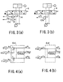
- a pressure sensor is installed in each chamber of a hydraulic cylinder, but, as shown in Fig. 3 (a), it is also possible to provide a line 14, which automatically conveys the load pressure of the pressure oil on the side where it flows into a hydraulic cylinder 2, 3 in accordance with the spool stroke direction of a flow control valve 4, 5, and to provide on this line 14 a pressure sensor 10c, 11c, which detects the load pressure P1, P2 of the pressure oil on the side where it flows into a hydraulic cylinder 2, 3. Doing this enables the number of pressure sensors to be reduced. Moreover, in this case, as shown in Fig.
- the effect produced is such that there is no need to provide a configuration for selecting the bottom pressure P1B (P2B) and the head pressure P1H (P2H) in differential pressure calculation means 8a' of the controller 8, as was required in Fig. 2.
- a stroke volume sensor 15, 16 such as a linear potentiometer or a magnetic moving volume sensor, which detects the actual stroke volume Sa1, Sa2 of a spool, is provided in a flow control valve 4, 5, and this detected stroke volume Sa1, Sa2 is used as a feedback volume, and the drive command value S1, S2 is used as a target value. Then, the error between this target value and the above-mentioned feedback volume S1 - Sa1, S2 - Sa2 is taken, and the product obtained by multiplying feedback gain G1, G2 by these errors is outputted to electromagnetic proportional pilot valves 12, 13, respectively, as control input. In this way, performing feedback control so that the above-mentioned errors S1 - Sa1, S2 - Sa2 work out to zero makes it possible to precisely match the aperture area to the target aperture area A1', A2'.
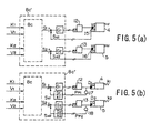
- a configuration like that shown in Fig. 5 (b) can also be used as another method for detecting actual stroke volume Sa1, Sa2.
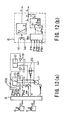
- Fig. 6 and Fig. 7 are diagrams showing configurations of the embodiment when detecting the across-valve differential pressure of flow control valves 4, 5 on the side where pressure oil flows out to a tank. These figures correspond to the above-mentioned Fig. 1 and Fig. 2, respectively.
- Fig. 6 differs from Fig. 1 in that, in place of pressure sensor 9 for the hydraulic pump 1, a pressure sensor 19, which detects tank pressure PT, is provided on a line that passes through the tank.
- P2B bottom chamber side, which is the side where pressure oil flows out to a tank
- P2B bottom chamber side, which is the side where pressure oil flows out to a tank
- P2B bottom chamber side, which is the side where pressure oil flows out to a tank
- operating levers 6, 7 are assumed to be electrical levers, but of course, conventional hydraulic pilot levers can be used in place of electrical levers.
- Fig. 9, Fig. 10 are diagrams showing a configuration of an embodiment that uses a hydraulic pilot lever, and correspond to the above-mentioned Fig. 1, Fig. 2, respectively.
- Pilot pressure proportional to lever control input is outputted from hydraulic pilot levers 6, 7 shown in Fig. 9 to electromagnetic pressure reducing valves 21, 22, respectively, and the pilot pressure is applied via these electromagnetic pressure reducing valves 21, 22 to flow control valves 4, 5, respectively.
- Differential pressures ⁇ P1, ⁇ P2 between pump pressure Pp and load pressures P1, P2 on the hydraulic cylinder inflow side are detected by pressure sensors 10d, 11d, respectively, and these detected differential pressures ⁇ P1, ⁇ P2 are each inputted to the controller 8.
- the minimum differential pressure ⁇ Pmin is determined from among inputted detected differential pressures ⁇ P1, ⁇ P2 by differential pressure calculation means 8a of controller 8 in Fig. 10, and the square roots of the ratios of the differential pressures and the minimum differential pressure ⁇ ( ⁇ Pmin/ ⁇ P1), ⁇ ( ⁇ Pmin/ ⁇ P2), respectively, are determined for each drive shaft by correction factor calculation means 8b.
- Signals, which specify these determined correction factors K1, K2, which are valued from 0 to 1.0, are outputted as drive control values to both electromagnetic pressure reducing valves 21, 22, which are the drive command value correction means 8c.
- One control system for a hydraulic pump is called positive control.
- This positive control system is a control system, whereby a lever control input by an operator is applied to the hydraulic pump as a demand.
- a positive control system is shown in Fig. 11 (a), (b).
- drive command values V1, V2 are inputted to a controller 8 as control input from operating levers 6, 7, and a number of revolutions signal RPM from a revolution sensor 24, which detects the actual number of revolutions of an engine 23, as well as a pump discharge pressure signal Pp from a pressure sensor 9, are also inputted to the controller 8.
- demand flows Q1, Q2 related to the respective drive command values V1, V2 are determined from a stored table, which specifies the drive command value - demand flow relationship, and the sum of these Q1, Q2 is the total flow Q12.
- the hydraulic pump 1 cannot output horsepower in excess of the horsepower currently being outputted by the engine 23.
- the maximum value of horsepower is limited by a maximum value Qmax on an equivalent horsepower curve of a P-Q chart, which is a relational expression of the discharge pressure Pp of the hydraulic pump 1 and the discharge flow Q.
- the smaller of the above-mentioned total demand flow Q12 and above-mentioned maximum value Qmax is selected, and this selected flow is used as the dischargeable flow Q for the hydraulic pump 1.
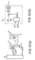
- control of the hydraulic pump 1 can also be performed stably by providing an unload valve 25 on the line that connects to a tank.
- the controller 8 controls the unload valve 25 (See Fig. 12 (b)) so as to apply an unload command value u to the solenoid of the unload valve 25 so that when operating levers 6, 7 are neutral, the minimum discharge volume of the hydraulic pump 1 flows in its entirety into the tank via the unload valve 25, and as the control inputs V1, V2 of operating levers 6, 7 increase, the flow from the unload valve 25 to the tank becomes smaller.
- responsiveness is good when a control lever is first operated from neutral, work machine jump can be prevented, and stable hydraulic pump control becomes possible.
- the least differential pressure can be actively maintained at the minimum differential pressure drive shaft by applying control so as to make the above-mentioned unload flow u small, or by applying control that increases the discharge flow Q of the hydraulic pump 1 (See Fig. 12 (b)).
- Another method of controlling a hydraulic pump is load sensing control.
- This load sensing control controls the discharge volume of the hydraulic pump so that the hydraulic pump discharge pressure only increases a prescribed value more than the maximum load pressure inside a hydraulic actuator during operation.
- Fig. 13 (a), (b) show an embodiment which uses this load sensing control.
- differential pressures ⁇ P1, ⁇ P2 across flow control valves 4, 5, respectively, are inputted to the controller 8, and the minimum differential pressure is determined by differential pressure calculation means 8a as described above. Then, the deviation APr - ⁇ Pmin between a prescribed target differential pressure ⁇ Pr (for example, 20kg/cm 2 ) and the above-mentioned minimum differential pressure ⁇ Pmin is determined, and the result of performing integration processing on the product of multiplying this deviation by control gain G is used as a pump swash plate position command L. This enables conventional pump load sensing control to be achieved electrically.
- variable capacity hydraulic pump 1 attempts to maintain the minimum differential pressure ⁇ Pmin at a fixed value ⁇ Pr at all times, but there are times when an operator requires a large flow, and when flow saturation occurs, the hydraulic pump becomes incapable of maintaining a prescribed minimum differential pressure.
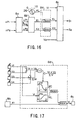
- a signal which specifies control inputs V1, V2 of operating levers 6, 7, and a signal, which specifies differential pressures ⁇ P1, ⁇ P2 detected by differential pressure sensors 10d, 11d, are inputted to the controller 8, and, as shown in Fig. 14 (b), processing, which circumscribes, in accordance to lever control input, the lower limit of a correction factor K calculated by correction factor calculation means 8b, is implemented in a correction factor controller 8d, which is provided between correction factor calculation means 8b and drive command value correction means 8c.
- a correction limit table which specifies a relationship wherein correction limit values K1L, K2L increase in the range between 0-1.0 as control inputs V1, V2 of operating levers 6, 7 increase, is provided in advance in the correction factor controller 8b. Accordingly, correction limit values corresponding to current control inputs V1, V2, respectively, are read out from the above-mentioned table, and the size of this read-out boom limit value K1L, arm limit value K2L is compared, respectively, to the size of each of the boom, arm correction factors K1, K2 outputted from correction factor calculation means 8b, and the largest of the correction limit value and correction factor is selected and outputted to drive command value correction means 8c.
- correction limit value K1L is near 0 at lever fine control (when V1 is small)
- correction factor K1 is larger, and correction factor K1 is selected.
- the correction limit value K1L also increases, thereby steadily narrowing the range of correction factor K1.
- correction factor K1 is forcibly set to 1, and the system switches over to a state wherein control input V1 is not corrected.
- control which makes full use of pressure compensation at fine control operation, and cuts off pressure compensation at full lever operation, is performed continuously in proportion to lever control input, making lever operability good no matter how large the lever control input, thus enhancing work efficiency.
- the current control system of a hydraulic pump is a load sensing system, and the discharge pressure of the hydraulic pump is controlled so that it increases only a prescribed target differential pressure ⁇ Pr higher than the maximum load pressure.
- correction factors K1, K2 can be determined directly from the above-mentioned prescribed target differential pressure ⁇ Pr without finding the minimum differential pressure ⁇ Pmin.
- each correction factor K1, K2 is determined directly by correction factor calculation means 8b from the ratio between the differential pressure of each shaft ⁇ P1, ⁇ P2, and the prescribed target differential pressure ⁇ Pr, without using differential pressure calculation means 8a to find the minimum differential pressure ⁇ Pmin. Then, in the same correction factor controller 8d as that depicted in Fig. 14, the lower limits of correction factors K1, K2, which were calculated using correction factor calculation means 8b, are calculated in accordance with lever control inputs V1, V2.
- control which makes full use of pressure compensation at fine control operation, and cuts off pressure compensation at full lever operation, is performed continuously in proportion to lever control input, producing the effect, whereby lever operability is good no matter how large the lever control input, and work efficiency improves.
- a setting apparatus which manually sets a correction limit value KL, which limits correction factors K1, K2, is provided in Fig. 16. This enables the operator to arbitrarily select the degree of pressure compensation in accordance with the job.
- correction factors K1, K2 outputted from correction factor calculation means 8b are always given preference as a result of size comparison by the correction factor controller 8d, allowing pressure compensation to work to the fullest. But since correction factors K1, K2 outputted from correction factor calculation means 8b are less than 1 when correction limit value KL is set to "1" by the setting apparatus, the result of size comparison is always the set value of "1,” and aperture area correction is not performed by drive command value correction means 8c. That is, "load-bearing" flow distribution is performed without pressure compensation coming into play.
- the hydraulic drive machine comprises four hydraulic actuators, boom, arm, bucket, swing, and that control inputs V1, V2, V3, V4, respectively, are outputted to a controller 8 from various operating levers corresponding to each hydraulic actuator.
- lever-sensitive variable pressure compensation control is performed for the boom only when the two shafts of the boom and arm are operated in combination.
- a correction limit table which specifies the relationship between the above-mentioned determined ratio c and correction limit value Kc.
- the relationship is such that when ratio c is 0, output Kc is 1, and as ratio c approaches 1, output Kc becomes smaller. Accordingly, correction limit value Kc outputted from this correction limit table is compared with a boom limit value K1L determined from control input V1 of the boom operating lever just as shown in Fig. 14, and the largest of these values is selected. Furthermore, this selected value is compared with correction factor K1 outputted from correction factor calculation means 8b, and the largest of these values is selected and outputted.
- correction limit value Kc approaches 0, and since the minimum differential pressure ⁇ Pmin matches up with self-detected differential pressure ⁇ P1 in correction factor calculation means 8b, correction factor K1 becomes 1, and, without recourse to correction limit values Kc, K1L, aperture area correction is not performed.
- lever-sensitive variable pressure compensation control is performed only when 2 shafts, the boom and arm, are operated in combination.
- excavation work whereby a predetermined locus is excavated while applying a certain degree of load pressure, is considered work that requires pressure compensation.
- boom load pressure P1 detected by a pressure sensor 9c is inputted to a correction factor controller 8d in the controller 8.
- a limit value table which specifies the relationship between load pressure P1 and correction limit value K1L, wherein the lower the load pressure P1, the closer correction limit value K1L gets to 1, and as load pressure P1 increases, correction limit value K1L approaches 0, is provided in the correction factor controller 8d. Accordingly, a correction limit value K1L corresponding to the current load pressure P1 is outputted from the correction limit value table, and the size of this outputted value is compared with the size of correction factor K1 outputted from correction factor calculation means 8b, the largest of these values is selected, and outputted to drive command value correction means 8c.
- correction factor K1 is considered 1 when the load on the boom is light
- pressure compensation becomes ineffective, but as the boom load pressure becomes higher, the degree of pressure compensation steadily increases.
- pressure compensation is fully effective when performing excavation work, wherein a predetermined locus is excavated while applying a certain degree of load pressure, and pressure compensation ceases to be effective when performing light load work that falls outside of such excavation operations, the above-mentioned excavation work can be performed efficiently, and improved fuel consumption and the facilitation of rough operations can be expected during light-load work.
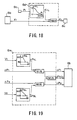
- Fig. 19 depicts an embodiment in which lever-sensitive variable pressure compensation control is applied.
- differential pressure calculation means 8e of controller 8 is differential pressure calculation means, which include a function that limits a detected differential pressure. That is, this differential pressure calculation means 8e is provided with a limit value table, which specifies the relationship between control inputs V1, V2 and upper limit differential pressures ⁇ P1L, ⁇ P2L, whereby, as control inputs V1, V2 become larger, upper limit differential pressures ⁇ P1L, ⁇ P2L become smaller.
- the various minimum differential pressures ⁇ P1, ⁇ P2 thus obtained for the boom, arm are also compared as to size, and the smaller thereof is selected and outputted as the minimum differential pressure ⁇ Pmin.
- variable pressure compensation control embodiment a different pattern can be set in the limit value variation pattern stored in the limit value table, in accordance with the type of work (work mode) currently being performed, and the combination of working machines currently being driven. This makes it possible to handle all sorts of work, and improves flexibility.
- the present invention can be applied to construction equipment, such as a hydraulic excavator, as well as to any other hydraulic drive machine. Further, the present invention is used primarily to control 2 working machines, such as a boom, arm, but, of course, it can also be applied to 3 or more working machines.
Claims (6)
- Dispositif de commande (8) pour une machine hydraulique d'entraínement qui comprend une pompe hydraulique (1), une pluralité d'actionneurs hydrauliques (2,3) placés en correspondance avec une pluralité d'éléments fonctionnels (6,7), et une pluralité de vannes fonctionnelles (4,5) pour apporter aux actionneurs hydrauliques (2,3) correspondants une huile sous pression évacuée de la pompe hydraulique (1) à un débit d'écoulement qui est en accord avec les entrées de commande des éléments fonctionnels (6,7), et qui entraíne les actionneurs hydrauliques (2,3) en fonction du fonctionnement des éléments fonctionnels (6,7) dans lequel le dispositif de commande (8) comprend :caractérisé en ce que :des moyens de détection de différence de pression pour détecter pour chaque vanne fonctionnelle (4,5) une différence de pression (ΔP1, ΔP2) entre une pression de l'huile sous pression s'écoulant dans la vanne fonctionnelle (4,5) et une pression de l'huile sous pression s'écoulant hors de la vanne fonctionnelle (4,5) ;des moyens de sélection de différence de pression minimale (8a) pour choisir une différence de pression minimale (ΔPmin) parmi les différences de pressions (ΔP1, ΔP2) détectées par les moyens de détection de différence de pression ;des moyens de calcul de facteur de correction (8b) pour calculer pour chaque élément fonctionnel (6,7) un facteur de correction (K1, K2) pour corriger, sur la base d'un rapport entre la différence de pression détectée de la vanne fonctionnelle (4,5) et la différence de pression minimale choisie, une entrée de commande (V1, V2) d'un élément fonctionnel (6,7) correspondant à la vanne fonctionnelle (4,5) ; etdes moyens de correction d'entrée de commande (8c) pour corriger l'entrée de commande d'un élément fonctionnel (6,7) correspondant utilisant le facteur de correction (K1, K2) calculé par les moyens de calcul de facteur de correction (8b).
- Dispositif de commande pour une machine hydraulique d'entraínement selon la revendication 1, caractérisé en ce que le facteur de correction (K1, K2) est exprimé par √(Δpmin/Δpi) quand la différence de pression minimale est ΔPmin, et la différence de pression détectée d'une vanne fonctionnelle i est Δpi.
- Dispositif de commande pour une machine hydraulique d'entraínement selon la revendication 1, caractérisé en ce que les moyens de détection de différence de pression détectent, parmi des restricteurs de la vanne fonctionnelle (4,5), une différence de pression des pressions aux entrée et sortie d'un restricteur sur un côté duquel l'huile sous pression s'écoute dans l'actionneur hydraulique (2,3).
- Dispositif de commande pour une machine hydraulique d'entraínement selon la revendication 1, caractérisé en ce que les moyens de détection de différence de pression détectent, parmi des restricteurs de la vanne fonctionnelle (4,5), une différence de pression des pressions à l'entrée et la sortie d'un restricteur sur un côté duquel l'huile sous pression s'écoule hors de l'actionneur hydraulique (2,3).
- Dispositif de commande pour une machine hydraulique d'entraínement selon la revendication 1, caractérisé en ce que la vanne fonctionnelle (4,5) alimente l'actionneur hydraulique (2,3) en huile sous pression, dont un débit s'accorde à une surface d'ouverture (A1, A2), l'élément fonctionnel (6,7) sort comme une entrée de commande une taille de la surface d'ouverture (A1, A2) de la vanne fonctionnelle (4,5), et les moyens de correction d'entrée de commande (8c) déterminent l'entrée de commande corrigée en multipliant le facteur de correction (K1, K2) par la surface d'ouverture (A1, A2) comme entrée de commande de l'élément fonctionnel (6,7).
- Dispositif de commande pour une machine hydraulique d'entraínement selon la revendication 1, caractérisé en ce que la vanne fonctionnelle (4,5) est soumise à une commande par rétroaction avec l'utilisation d'un volume d'entraínement d'un tiroir, comme valeur cible, correspondant à une entrée de commande corrigée par les moyens de correction d'entrée de commande (8c) et un volume d'entraínement réel du tiroir comme volume de rétroaction.
Priority Applications (2)
| Application Number | Priority Date | Filing Date | Title |
|---|---|---|---|
| EP07000473A EP1798346B1 (fr) | 1996-02-28 | 1997-02-28 | Dispositif de commande pour machine à entraînement hydraulique |
| EP05000030A EP1553231B1 (fr) | 1996-02-28 | 1997-02-28 | Dispositif de commande pour machine hydraulique d'entraînement |
Applications Claiming Priority (7)
| Application Number | Priority Date | Filing Date | Title |
|---|---|---|---|
| JP4155496 | 1996-02-28 | ||
| JP41554/96 | 1996-02-28 | ||
| JP04155496A JP3673003B2 (ja) | 1996-02-28 | 1996-02-28 | 油圧駆動機械の制御装置 |
| JP04310196A JP3723270B2 (ja) | 1996-02-29 | 1996-02-29 | 油圧駆動機械の制御装置 |
| JP4310196 | 1996-02-29 | ||
| JP43101/96 | 1996-02-29 | ||
| PCT/JP1997/000597 WO1997032135A1 (fr) | 1996-02-28 | 1997-02-28 | Dispositif de commande pour machine hydraulique d'entrainement |
Related Child Applications (1)
| Application Number | Title | Priority Date | Filing Date |
|---|---|---|---|
| EP05000030A Division EP1553231B1 (fr) | 1996-02-28 | 1997-02-28 | Dispositif de commande pour machine hydraulique d'entraînement |
Publications (3)
| Publication Number | Publication Date |
|---|---|
| EP0884482A1 EP0884482A1 (fr) | 1998-12-16 |
| EP0884482A4 EP0884482A4 (fr) | 1999-05-19 |
| EP0884482B1 true EP0884482B1 (fr) | 2005-01-05 |
Family
ID=26381194
Family Applications (3)
| Application Number | Title | Priority Date | Filing Date |
|---|---|---|---|
| EP07000473A Expired - Lifetime EP1798346B1 (fr) | 1996-02-28 | 1997-02-28 | Dispositif de commande pour machine à entraînement hydraulique |
| EP97903627A Expired - Lifetime EP0884482B1 (fr) | 1996-02-28 | 1997-02-28 | Dispositif de commande pour machine hydraulique d'entrainement |
| EP05000030A Expired - Lifetime EP1553231B1 (fr) | 1996-02-28 | 1997-02-28 | Dispositif de commande pour machine hydraulique d'entraînement |
Family Applications Before (1)
| Application Number | Title | Priority Date | Filing Date |
|---|---|---|---|
| EP07000473A Expired - Lifetime EP1798346B1 (fr) | 1996-02-28 | 1997-02-28 | Dispositif de commande pour machine à entraînement hydraulique |
Family Applications After (1)
| Application Number | Title | Priority Date | Filing Date |
|---|---|---|---|
| EP05000030A Expired - Lifetime EP1553231B1 (fr) | 1996-02-28 | 1997-02-28 | Dispositif de commande pour machine hydraulique d'entraînement |
Country Status (5)
| Country | Link |
|---|---|
| US (2) | US6173573B1 (fr) |
| EP (3) | EP1798346B1 (fr) |
| KR (1) | KR19990087335A (fr) |
| DE (3) | DE69738461D1 (fr) |
| WO (1) | WO1997032135A1 (fr) |
Families Citing this family (42)
| Publication number | Priority date | Publication date | Assignee | Title |
|---|---|---|---|---|
| FR2807118B1 (fr) * | 2000-03-28 | 2002-07-05 | Mannesmann Rexroth Sa | Circuit hydraulique pour l'actionnement de recepteurs hydrauliques multiples |
| US6735486B2 (en) * | 2001-05-01 | 2004-05-11 | Altec Industries | Side load detection and protection system for rotatable equipment |
| US6871710B1 (en) | 2001-05-01 | 2005-03-29 | Altec Industries, Inc. | Rotational float for rotating equipment |
| US6685138B1 (en) * | 2002-11-25 | 2004-02-03 | The Boeing Company | Augmenting flight control surface actuation system and method |
| JP3992612B2 (ja) * | 2002-12-26 | 2007-10-17 | 株式会社クボタ | バックホウの油圧回路構造 |
| DE10342037A1 (de) * | 2003-09-11 | 2005-04-07 | Bosch Rexroth Ag | Steueranordnung und Verfahren zur Druckmittelversorgung von zumindest zwei hydraulischen Verbrauchern |
| JP4096900B2 (ja) * | 2004-03-17 | 2008-06-04 | コベルコ建機株式会社 | 作業機械の油圧制御回路 |
| US7093383B2 (en) * | 2004-03-26 | 2006-08-22 | Husco International Inc. | Automatic hydraulic load leveling system for a work vehicle |
| US6976357B1 (en) * | 2004-06-23 | 2005-12-20 | Husco International, Inc. | Conduit loss compensation for a distributed electrohydraulic system |
| DE112005001879B4 (de) * | 2004-08-02 | 2019-03-14 | Komatsu Ltd. | Steuerungsvorrichtung und Steuerungsverfahren für Fluiddruckstellantrieb |
| ATE488649T1 (de) * | 2004-09-28 | 2010-12-15 | Agco Sa | Steuersystem für einen lader. |
| KR100641393B1 (ko) * | 2004-12-07 | 2006-11-01 | 볼보 컨스트럭션 이키프먼트 홀딩 스웨덴 에이비 | 유압제어회로 및 유압제어방법 |
| US7089733B1 (en) * | 2005-02-28 | 2006-08-15 | Husco International, Inc. | Hydraulic control valve system with electronic load sense control |
| US7430954B2 (en) * | 2005-09-26 | 2008-10-07 | Kubota Corporation | Work machine |
| EP1954888A1 (fr) * | 2005-11-10 | 2008-08-13 | Volvo Construction Equipment AB | Chargeuse |
| US20070146442A1 (en) * | 2005-11-14 | 2007-06-28 | Mydata Automation Ab | System, assembly and method for jetting viscous medium onto a substrate |
| US7834560B2 (en) * | 2007-07-26 | 2010-11-16 | Leviton Manufacturing Co., Inc. | Dimming system powered by two current sources and having an operation indicator module |
| JP4825765B2 (ja) * | 2007-09-25 | 2011-11-30 | 株式会社クボタ | バックホーの油圧システム |
| DE102007048697A1 (de) * | 2007-10-11 | 2009-04-16 | Deere & Company, Moline | Hydraulische Hubeinrichtung |
| DE102007059491B3 (de) * | 2007-12-11 | 2009-07-09 | Sauer-Danfoss Gmbh & Co Ohg | Verfahren und Schaltungsanordnung zur Druckmittelversorgung von zumindest zwei hydraulischen Verbrauchern |
| US8511080B2 (en) * | 2008-12-23 | 2013-08-20 | Caterpillar Inc. | Hydraulic control system having flow force compensation |
| FR2942279B1 (fr) * | 2009-02-19 | 2016-04-15 | Etablissements Emily | Machine du type comprenant un moteur hydraulique destine a entrainer a rotation un accessoire |
| JP5161155B2 (ja) * | 2009-06-12 | 2013-03-13 | 株式会社小松製作所 | 作業機械および作業機械の制御方法 |
| IT1397794B1 (it) * | 2010-01-26 | 2013-01-24 | Cifa Spa | Dispositivo per il controllo attivo delle vibrazioni di un braccio articolato per il pompaggio di calcestruzzo. |
| JP5351813B2 (ja) * | 2010-03-31 | 2013-11-27 | 株式会社クボタ | 作業車の油圧システム |
| KR20110127343A (ko) * | 2010-05-19 | 2011-11-25 | 두산산업차량 주식회사 | 중장비 작업기의 상승속도 제어장치 |
| KR101847882B1 (ko) * | 2010-12-28 | 2018-04-11 | 볼보 컨스트럭션 이큅먼트 에이비 | 건설기계용 가변용량형 유압펌프 유량 제어방법 |
| JP5631829B2 (ja) * | 2011-09-21 | 2014-11-26 | 住友重機械工業株式会社 | 油圧制御装置及び油圧制御方法 |
| JP5631830B2 (ja) | 2011-09-21 | 2014-11-26 | 住友重機械工業株式会社 | 油圧制御装置及び油圧制御方法 |
| CN104838073B (zh) * | 2012-11-23 | 2017-03-08 | 沃尔沃建造设备有限公司 | 用于控制工程机械的优先功能的设备和方法 |
| WO2015066182A1 (fr) * | 2013-10-29 | 2015-05-07 | Raven Industries, Inc. | Système de commande de cylindrée hydraulique |
| CN103807236B (zh) * | 2014-01-22 | 2015-09-16 | 浙江大学 | 阀控单元负载口独立控制多缸流量分配液压系统 |
| US9759212B2 (en) | 2015-01-05 | 2017-09-12 | Danfoss Power Solutions Inc. | Electronic load sense control with electronic variable load sense relief, variable working margin, and electronic torque limiting |
| WO2017099230A1 (fr) * | 2015-12-10 | 2017-06-15 | 川崎重工業株式会社 | Système d'entraînement hydraulique |
| EP4155556A1 (fr) * | 2017-12-14 | 2023-03-29 | Volvo Construction Equipment AB | Machine hydraulique |
| CN109058194A (zh) * | 2018-10-11 | 2018-12-21 | 徐工集团工程机械有限公司 | 作业执行机构的液压控制系统及其控制方法和作业机械 |
| JP7190933B2 (ja) * | 2019-02-15 | 2022-12-16 | 日立建機株式会社 | 建設機械 |
| CN111102253A (zh) * | 2019-12-25 | 2020-05-05 | 长沙中达智能科技有限公司 | 一种液压驱动机构速度的控制装置与方法 |
| FR3106166B1 (fr) * | 2020-01-09 | 2022-01-21 | Bosch Gmbh Robert | « Installation de commande d’une installation hydraulique à plusieurs récepteurs fonctionnant en parallèle ». |
| US11614101B1 (en) | 2021-10-26 | 2023-03-28 | Cnh Industrial America Llc | System and method for controlling hydraulic valve operation within a work vehicle |
| US11608615B1 (en) | 2021-10-26 | 2023-03-21 | Cnh Industrial America Llc | System and method for controlling hydraulic valve operation within a work vehicle |
| IT202100027794A1 (it) * | 2021-10-29 | 2023-04-29 | Cnh Ind Italia Spa | Metodo e sistema di controllo di un circuito idraulico di un veicolo da lavoro |
Family Cites Families (16)
| Publication number | Priority date | Publication date | Assignee | Title |
|---|---|---|---|---|
| US4537029A (en) | 1982-09-23 | 1985-08-27 | Vickers, Incorporated | Power transmission |
| DE3447709C1 (de) | 1984-12-28 | 1986-04-30 | Karl 7298 Loßburg Hehl | Steuervorrichtung fuer den hydraulischen Kreislauf einer Kunststoff-Spritzgiessmaschine |
| JPH0450505A (ja) * | 1990-06-15 | 1992-02-19 | Hitachi Constr Mach Co Ltd | 建設機械の油圧駆動装置 |
| JPH0478307U (fr) * | 1990-11-20 | 1992-07-08 | ||
| DK0515608T3 (da) * | 1990-12-15 | 1995-06-12 | Barmag Barmer Maschf | Hydrauliksystem |
| US5138838A (en) | 1991-02-15 | 1992-08-18 | Caterpillar Inc. | Hydraulic circuit and control system therefor |
| JPH04351304A (ja) * | 1991-05-29 | 1992-12-07 | Hitachi Constr Mach Co Ltd | 油圧駆動装置 |
| US5167121A (en) * | 1991-06-25 | 1992-12-01 | University Of British Columbia | Proportional hydraulic control |
| JPH05248403A (ja) * | 1992-01-13 | 1993-09-24 | Caterpillar Inc | 油圧制御装置 |
| DE69311239T2 (de) * | 1992-02-18 | 1997-10-16 | Hitachi Construction Machinery | Hydraulisches antriebsystem |
| JP2602760B2 (ja) | 1992-07-23 | 1997-04-23 | 石原薬品株式会社 | 無電解メッキ浴の自動管理方法 |
| JP3026527B2 (ja) | 1992-07-27 | 2000-03-27 | 株式会社ジャパンエナジー | 無電解めっきの前処理方法および前処理液 |
| JPH06336750A (ja) * | 1993-05-27 | 1994-12-06 | Hitachi Constr Mach Co Ltd | 建設機械の油圧駆動装置 |
| GB9503854D0 (en) * | 1995-02-25 | 1995-04-19 | Ultra Hydraulics Ltd | Electrohydraulic proportional control valve assemblies |
| US5666806A (en) | 1995-07-05 | 1997-09-16 | Caterpillar Inc. | Control system for a hydraulic cylinder and method |
| JP3113547B2 (ja) * | 1995-07-19 | 2000-12-04 | 新キャタピラー三菱株式会社 | 油圧制御回路 |
-
1997
- 1997-02-28 EP EP07000473A patent/EP1798346B1/fr not_active Expired - Lifetime
- 1997-02-28 EP EP97903627A patent/EP0884482B1/fr not_active Expired - Lifetime
- 1997-02-28 DE DE69738461T patent/DE69738461D1/de not_active Expired - Lifetime
- 1997-02-28 KR KR1019980706744A patent/KR19990087335A/ko not_active Application Discontinuation
- 1997-02-28 DE DE69740086T patent/DE69740086D1/de not_active Expired - Lifetime
- 1997-02-28 DE DE69732177T patent/DE69732177D1/de not_active Expired - Lifetime
- 1997-02-28 EP EP05000030A patent/EP1553231B1/fr not_active Expired - Lifetime
- 1997-02-28 WO PCT/JP1997/000597 patent/WO1997032135A1/fr active IP Right Grant
-
1998
- 1998-02-28 US US09/125,691 patent/US6173573B1/en not_active Expired - Fee Related
-
2000
- 2000-10-19 US US09/691,229 patent/US6438953B1/en not_active Expired - Lifetime
Also Published As
| Publication number | Publication date |
|---|---|
| DE69740086D1 (de) | 2011-02-03 |
| US6438953B1 (en) | 2002-08-27 |
| KR19990087335A (ko) | 1999-12-27 |
| EP1798346B1 (fr) | 2010-12-22 |
| WO1997032135A1 (fr) | 1997-09-04 |
| EP1553231B1 (fr) | 2008-01-09 |
| DE69738461D1 (de) | 2008-02-21 |
| EP0884482A4 (fr) | 1999-05-19 |
| EP1553231A2 (fr) | 2005-07-13 |
| US6173573B1 (en) | 2001-01-16 |
| EP1798346A3 (fr) | 2008-01-09 |
| EP1798346A2 (fr) | 2007-06-20 |
| EP0884482A1 (fr) | 1998-12-16 |
| EP1553231A3 (fr) | 2005-07-20 |
| DE69732177D1 (de) | 2005-02-10 |
Similar Documents
| Publication | Publication Date | Title |
|---|---|---|
| EP0884482B1 (fr) | Dispositif de commande pour machine hydraulique d'entrainement | |
| US5267440A (en) | Hydraulic control system for construction machine | |
| JP3805383B2 (ja) | 作業アタッチメントを流体システムに統合する制御装置 | |
| EP2107252B1 (fr) | Dispositif de commande de pompe pour machine de chantier | |
| EP0597109B1 (fr) | Systeme de commande hydraulique | |
| KR950007624B1 (ko) | 유압펌프의 제어장치 | |
| EP0644335A1 (fr) | Moteur hydraulique pour engin de chantier hydraulique | |
| EP2587072B1 (fr) | Système de commande d'écoulement pour une pompe hydraulique de machine de construction | |
| EP0796952A1 (fr) | Systeme de commande d'engins de chantier | |
| US11105348B2 (en) | System for controlling construction machinery and method for controlling construction machinery | |
| JP2651079B2 (ja) | 油圧建設機械 | |
| EP0440807B1 (fr) | Appareil d'entrainement hydraulique pour un engin de chantier ou de genie civil | |
| JP4807888B2 (ja) | 油圧駆動機械の制御装置 | |
| JP3491940B2 (ja) | 可変容量型油圧ポンプの制御装置 | |
| JP2008224039A (ja) | 油圧駆動機械の制御装置 | |
| JP3723270B2 (ja) | 油圧駆動機械の制御装置 | |
| JP3673003B2 (ja) | 油圧駆動機械の制御装置 | |
| CN113474519A (zh) | 工作机器的液压控制回路 | |
| JPH04258505A (ja) | 油圧建設機械の駆動制御装置 | |
| JP3175992B2 (ja) | 油圧駆動機械の制御装置 | |
| JPH06200878A (ja) | 作業機械におけるパワーユニットの出力制御装置 | |
| JP3305801B2 (ja) | 油圧駆動機械の制御装置 | |
| JP3766512B2 (ja) | 油圧駆動機械の制御装置 | |
| JP3330340B2 (ja) | 油圧駆動機械の制御装置 | |
| JP2006002943A (ja) | 油圧駆動機械の制御装置 |
Legal Events
| Date | Code | Title | Description |
|---|---|---|---|
| PUAI | Public reference made under article 153(3) epc to a published international application that has entered the european phase |
Free format text: ORIGINAL CODE: 0009012 |
|
| AK | Designated contracting states |
Kind code of ref document: A1 Designated state(s): BE DE FR GB IT |
|
| 17P | Request for examination filed |
Effective date: 19980916 |
|
| A4 | Supplementary search report drawn up and despatched |
Effective date: 19990407 |
|
| AK | Designated contracting states |
Kind code of ref document: A4 Designated state(s): BE DE FR GB IT |
|
| RHK1 | Main classification (correction) |
Ipc: E02F 9/22 |
|
| 17Q | First examination report despatched |
Effective date: 20020604 |
|
| GRAP | Despatch of communication of intention to grant a patent |
Free format text: ORIGINAL CODE: EPIDOSNIGR1 |
|
| GRAS | Grant fee paid |
Free format text: ORIGINAL CODE: EPIDOSNIGR3 |
|
| GRAA | (expected) grant |
Free format text: ORIGINAL CODE: 0009210 |
|
| AK | Designated contracting states |
Kind code of ref document: B1 Designated state(s): BE DE FR GB IT |
|
| PG25 | Lapsed in a contracting state [announced via postgrant information from national office to epo] |
Ref country code: IT Free format text: LAPSE BECAUSE OF FAILURE TO SUBMIT A TRANSLATION OF THE DESCRIPTION OR TO PAY THE FEE WITHIN THE PRE;WARNING: LAPSES OF ITALIAN PATENTS WITH EFFECTIVE DATE BEFORE 2007 MAY HAVE OCCURRED AT ANY TIME BEFORE 2007. THE CORRECT EFFECTIVE DATE MAY BE DIFFERENT FROM THE ONE RECORDED.SCRIBED TIME-LIMIT Effective date: 20050105 Ref country code: FR Free format text: LAPSE BECAUSE OF NON-PAYMENT OF DUE FEES Effective date: 20050105 Ref country code: BE Free format text: LAPSE BECAUSE OF FAILURE TO SUBMIT A TRANSLATION OF THE DESCRIPTION OR TO PAY THE FEE WITHIN THE PRESCRIBED TIME-LIMIT Effective date: 20050105 |
|
| REG | Reference to a national code |
Ref country code: GB Ref legal event code: FG4D |
|
| REF | Corresponds to: |
Ref document number: 69732177 Country of ref document: DE Date of ref document: 20050210 Kind code of ref document: P |
|
| PG25 | Lapsed in a contracting state [announced via postgrant information from national office to epo] |
Ref country code: DE Free format text: LAPSE BECAUSE OF FAILURE TO SUBMIT A TRANSLATION OF THE DESCRIPTION OR TO PAY THE FEE WITHIN THE PRESCRIBED TIME-LIMIT Effective date: 20050406 |
|
| PGFP | Annual fee paid to national office [announced via postgrant information from national office to epo] |
Ref country code: BE Payment date: 20050408 Year of fee payment: 9 |
|
| PLBE | No opposition filed within time limit |
Free format text: ORIGINAL CODE: 0009261 |
|
| STAA | Information on the status of an ep patent application or granted ep patent |
Free format text: STATUS: NO OPPOSITION FILED WITHIN TIME LIMIT |
|
| 26N | No opposition filed |
Effective date: 20051006 |
|
| REG | Reference to a national code |
Ref country code: GB Ref legal event code: FG4D |
|
| EN | Fr: translation not filed | ||
| PGFP | Annual fee paid to national office [announced via postgrant information from national office to epo] |
Ref country code: GB Payment date: 20110223 Year of fee payment: 15 |
|
| GBPC | Gb: european patent ceased through non-payment of renewal fee |
Effective date: 20120228 |
|
| PG25 | Lapsed in a contracting state [announced via postgrant information from national office to epo] |
Ref country code: GB Free format text: LAPSE BECAUSE OF NON-PAYMENT OF DUE FEES Effective date: 20120228 |