EP0884185A2 - Bilderzeugungsverfahren und Bilderzeugungsgerät dafür - Google Patents
Bilderzeugungsverfahren und Bilderzeugungsgerät dafür Download PDFInfo
- Publication number
- EP0884185A2 EP0884185A2 EP98110682A EP98110682A EP0884185A2 EP 0884185 A2 EP0884185 A2 EP 0884185A2 EP 98110682 A EP98110682 A EP 98110682A EP 98110682 A EP98110682 A EP 98110682A EP 0884185 A2 EP0884185 A2 EP 0884185A2
- Authority
- EP
- European Patent Office
- Prior art keywords
- liquid
- ink
- image forming
- recovery process
- ejection head
- Prior art date
- Legal status (The legal status is an assumption and is not a legal conclusion. Google has not performed a legal analysis and makes no representation as to the accuracy of the status listed.)
- Granted
Links
- 238000000034 method Methods 0.000 title claims description 19
- 239000007788 liquid Substances 0.000 claims abstract description 151
- 238000011084 recovery Methods 0.000 claims abstract description 69
- 238000007639 printing Methods 0.000 claims abstract description 55
- 239000000428 dust Substances 0.000 abstract description 7
- 239000000976 ink Substances 0.000 description 190
- 239000002699 waste material Substances 0.000 description 15
- 238000003860 storage Methods 0.000 description 12
- 238000004891 communication Methods 0.000 description 9
- 238000004140 cleaning Methods 0.000 description 8
- 238000010276 construction Methods 0.000 description 8
- 230000015572 biosynthetic process Effects 0.000 description 5
- 238000009835 boiling Methods 0.000 description 4
- 230000000694 effects Effects 0.000 description 4
- 238000010438 heat treatment Methods 0.000 description 4
- 239000004744 fabric Substances 0.000 description 3
- 230000005499 meniscus Effects 0.000 description 3
- 238000001816 cooling Methods 0.000 description 2
- 230000006870 function Effects 0.000 description 2
- 239000002184 metal Substances 0.000 description 2
- 238000012986 modification Methods 0.000 description 2
- 230000004048 modification Effects 0.000 description 2
- 230000010349 pulsation Effects 0.000 description 2
- 239000011347 resin Substances 0.000 description 2
- 229920005989 resin Polymers 0.000 description 2
- 230000005856 abnormality Effects 0.000 description 1
- 230000005540 biological transmission Effects 0.000 description 1
- 230000004397 blinking Effects 0.000 description 1
- 230000000903 blocking effect Effects 0.000 description 1
- 239000003086 colorant Substances 0.000 description 1
- 230000006835 compression Effects 0.000 description 1
- 238000007906 compression Methods 0.000 description 1
- 239000000470 constituent Substances 0.000 description 1
- 238000000151 deposition Methods 0.000 description 1
- 238000007599 discharging Methods 0.000 description 1
- 238000001035 drying Methods 0.000 description 1
- 238000007786 electrostatic charging Methods 0.000 description 1
- 230000002708 enhancing effect Effects 0.000 description 1
- 239000011521 glass Substances 0.000 description 1
- 230000010365 information processing Effects 0.000 description 1
- 230000000977 initiatory effect Effects 0.000 description 1
- 238000007641 inkjet printing Methods 0.000 description 1
- 238000005304 joining Methods 0.000 description 1
- 239000004973 liquid crystal related substance Substances 0.000 description 1
- 239000000463 material Substances 0.000 description 1
- 238000002156 mixing Methods 0.000 description 1
- 238000005086 pumping Methods 0.000 description 1
- 238000004513 sizing Methods 0.000 description 1
- 239000004575 stone Substances 0.000 description 1
- 239000004753 textile Substances 0.000 description 1
- 238000011144 upstream manufacturing Methods 0.000 description 1
- 239000002023 wood Substances 0.000 description 1
Images


Classifications
-
- B—PERFORMING OPERATIONS; TRANSPORTING
- B41—PRINTING; LINING MACHINES; TYPEWRITERS; STAMPS
- B41J—TYPEWRITERS; SELECTIVE PRINTING MECHANISMS, i.e. MECHANISMS PRINTING OTHERWISE THAN FROM A FORME; CORRECTION OF TYPOGRAPHICAL ERRORS
- B41J2/00—Typewriters or selective printing mechanisms characterised by the printing or marking process for which they are designed
- B41J2/005—Typewriters or selective printing mechanisms characterised by the printing or marking process for which they are designed characterised by bringing liquid or particles selectively into contact with a printing material
- B41J2/01—Ink jet
- B41J2/135—Nozzles
- B41J2/165—Prevention or detection of nozzle clogging, e.g. cleaning, capping or moistening for nozzles
- B41J2/16517—Cleaning of print head nozzles
- B41J2/1652—Cleaning of print head nozzles by driving a fluid through the nozzles to the outside thereof, e.g. by applying pressure to the inside or vacuum at the outside of the print head
Definitions
- the present invention relates to an image forming method and an apparatus for forming an image on a printing medium by ejecting a liquid from a liquid ejecting head. More particularly, the invention is suitable for application to an ink-jet printer mounted a full-line type ink-jet head, in which a plurality of ejection openings for liquid are arranged over entire width of an image forming region of the printing medium.
- An ink-jet printer for forming a desired image by ejecting ink droplet onto a paper, a cloth, a resin, a metal and the like is featured in non-contact with respect to a printing medium and thus is superior in low noise, high printing speed, capability of high resolution printing, easiness of color printing, and capability of down-sizing of the overall apparatus.
- a printer shown in Fig. 10 in which a plurality of elongated so-called full-line type ink-jet heads each having a plurality of ejection openings arrayed over the entire width of an image forming region of a printing medium, are arranged in a feeding direction of the printing medium.
- the printer includes four ink cartridges 33Y, 33M, 33C and 33B respectively storing an yellow ink, a magenta ink, a cyan ink, and a black ink (hereinafter referred to as ink cartridge 33) and four ink-jet heads 21Y, 21M, 21C and 21B (hereinafter referred to as ink-jet head 22) connected to respective ink cartridges 33 via ink supply tubes 32, respectively.
- head moving means 64 for recovery process which is controlled an operation by the control unit 60, the ink-jet heads 21 are moved up and down with respect to the platen 63.
- capping members 22 for performing recovery process of the ink-jet heads 21 by performing preliminary ejection of old inks within not shown ink passages provided within the ink-jet heads 21 from the ejection openings in advance of printing operation with respect to a printing paper 65 are arranged in a condition shifted for half pitch with respect to arrangement interval of the ink-jet heads 21.
- moving means 66 which is controlled an operation by the control unit 60, the capping members 22 are moved to positions immediately below the ink-jet heads 21 at recovery process position so as to receive waste inks ejected from the ejection openings.
- the feeding belt 62 feeding the printing paper 65 is wound around a driving roller 68 connected to a belt driving motor 67. Driving direction of the feeding belt 62 is switched by a motor driver 69 connected to the control unit 60.
- an electrostatic charger 70 is provided for electrostatic charging the feeding belt 62 for sticking the printing paper 65 on the feeding belt 62.
- the electrostatic charger 70 is switched ON and OFF by a driver 71 connected to the control unit 60.
- a paper feeding motor 73 for rotatingly driving the pair of paper feeding rollers 72 is connected to a pair of paper feeding rollers 72.
- the paper feeding motor 73 is switched the operation by a motor driver 74 connected to the control unit 60.
- the ink-jet heads 21 is elevated to the recovery process position away from the platen 63. Then, the capping member 22 is moved immediately below the ink-jet heads 21. Then, after recovery operation for the ink-jet heads 21, the capping member 22 is returned to an initial position. Also, the ink-jet heads 21 are moved toward the platen up to the image forming position. Then, the electrostatic charger 70 is actuated while the feeding belt 62 is driven. Also, the printing paper 65 is mounted on the feeding belt 62 by the paper feeding roller 72, and a desired color image is formed on the printing paper 65 by the ink-jet heads 21.
- the ink-jet heads 21 is located on the upper side of the ink cartridges 33. A problem to cause leakage of the ink through the ejection openings of the ink-jet heads 21 due to a liquid pressure of the ink stored in the ink cartridges 33 can be successfully prevented.
- an ink surface (ink meniscus) M of the ejection openings 40 is located at a position shown by a two dotted line at the image forming position, namely at an ejection opening surface 44 where the ejection openings 40 are formed, and whereas, at the recovery process position above the image forming position, a waterhead difference between the ink surface M and the ink cartridge 33 becomes large to cause recession of the ink surface M into the ink passage 58, as shown by the solid line.
- Such drawback may be caused not only in the ink but also in treatment liquid for adjusting printing ability of the ink on and/or in the printing medium.
- An object of the present invention is to provide an image forming method which can successfully prevent drawback of sucking foreign matter, such as dust or the like from the ejection openings into ink passages even when a liquid ejection head ejecting a liquid is elevated from an image forming position to a recovery process position.
- Another object of the present invention is to provide an image forming apparatus which can implement the image forming method set forth above.
- the first aspect of the present invention is an image forming method forming an image on a printing medium in an image forming position utilizing a liquid ejection head for forming the image on the printing medium by ejecting liquid in the image forming position, comprising:
- the second aspect of the present invention is an apparatus for forming an image on a printing medium utilizing a liquid ejection head provided with an ejection opening for ejecting liquid, comprising:
- the liquid ejection head when the image is formed on the printing medium, the liquid ejection head is moved into the image forming position by the head moving means to form the image on the printing medium using the liquid ejection head at the image forming position.
- the liquid supply passage is closed by operating the closing means to restrict flow of liquid between the ejection opening of the liquid ejection head and the liquid supply passage.
- the closure means is again operated to open the liquid supply passage, and recovery process of the liquid ejection head is performed by the recovery process means at the recovery process position.
- the liquid ejection head effected the recovery process is again returned to the image forming position by the head moving means and image formation on the printing medium is performed.
- the present invention when recovery process is performed in order to recover ejecting condition of liquid from the liquid ejection head at the recovery process position set on the upper side of the image forming position, since the liquid supply passage for supplying liquid to the liquid ejection head is closed during movement of the liquid ejection head from the image forming position to the recovery process position, even when the liquid ejection head for ejecting liquid is elevated from the image forming position to the recovery process position, a problem of suction of foreign matter, such as dust or the like into the ink passage from the ejection opening can be successfully prevented.
- the recovery process position may include a capping position for covering an ejection opening surface provided with an ejection opening of the liquid ejection head for ejecting liquid, and a wiping position set on upper side of the capping position for wiping the ejection opening surface.
- the recovery process may include at least one of steps of performing preliminary ejection of liquid from the ejection opening of the liquid ejection head at the capping position, expelling liquid from the ejection opening of the liquid ejection head by pressurizing the liquid supply passage, and sucking liquid from the ejection opening of the liquid ejection head.
- Liquid may be ink or treatment liquid for adjusting printing ability of the ink on and/or in the printing medium.
- the recovery process position may include a capping position and a wiping position located above the capping position, the recovery process means having a capping member for covering the ejection opening surface provided with an ejection opening of the liquid ejection head ejecting liquid at the capping position and a wiping member for wiping the ejection opening surface at the wiping position.
- the recovery process means may preliminary eject liquid from the ejection opening of the liquid ejection head at the capping position, expelling liquid from the ejection opening of the liquid ejection head by actuating the liquid supply means or sucking liquid from the ejection opening of the liquid ejection head via the capping member.
- the liquid ejection head may have an ejection energy generating portion for ejecting liquid from the ejection opening.
- the ejection energy generating portion may have an electrothermal transducer for generating thermal energy.
- the ejection openings may be provided for the liquid ejection head and may be arranged over the entire width of a printing region of the printing medium.
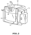
- FIG. 2 An external appearance of the preferred embodiment is shown in Fig. 2.
- the reference numeral 11 denotes a feeder cover storing cut-sheet 20 as a printing medium
- 12 denotes an upper cover for storing a head unit and opening and closing a feeding portion for the cut-sheet 20
- 13 denotes a front cover for loading and unloading ink cartridges 33 (see Figs. 1 and 5) storing respective colors of inks.
- the reference numeral 14 denotes a power switch of the card printer
- 15 denotes a ready lamp which is lighted when the card printer can be used
- 16 denotes a liquid crystal panel notifying condition of the card printer, such as error message and the like
- 17 denotes an error lamp which lighted when abnormality is caused in the card printer
- 18 denotes an on-line lamp which is lighted when the card printer is in on-line condition with a not shown host system
- 18a is a data lamp which is blinking when a printing data is stored in a not shown memory in the card printer.
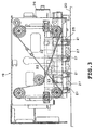
- a head unit 19 includes a plurality of ink-jet heads 21 respectively arranged ejection openings 40 (see Fig. 1) over the entire width of an image forming region in a width direction perpendicular to a feeding direction (left and right direction in Fig. 3) of the cut-sheet 20, in order to form an image on the cut-sheet 20 placed on the not shown platen.
- a head unit 19 includes a plurality of ink-jet heads 21 respectively arranged ejection openings 40 (see Fig. 1) over the entire width of an image forming region in a width direction perpendicular to a feeding direction (left and right direction in Fig. 3) of the cut-sheet 20, in order to form an image on the cut-sheet 20 placed on the not shown platen.
- a feeding direction left and right direction in Fig. 3
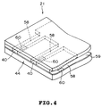
- each electrothermal transducer 60 has an electrothermal transducer 60 generating thermal energy for causing film boiling in the ink as an energy to be utilized for ejecting the ink, in an intermediate position of each individual ink passage 58 communicating between each ejection opening 40 and a common liquid chamber 59.
- the head unit 19 has the capping member 22 for receiving the ink ejected from the ejection openings 40 of each ink-jet head 21 and preventing the ink from drying in the vicinity of the ejection opening 40 and a recovering unit 24 (see Fig. 1) having a wiping blade 23 removing residual ink and the like on the ejection opening surface 44 (see Fig. 1), in which the ejection opening 40 opens, by wiping.
- the head unit 19 includes a driving unit which vertically moves upward a head holder unit 25 supporting each ink-jet head 21 from the image forming position opposing the cut-sheet 20 to the recovery process position and also horizontally moves the recovering unit 24 along the feeding direction of the cut-sheet 20 in a predetermined magnitude, a cooling unit 26 for cooling the ink-jet head 21, and so on.
- the recovery process position includes a capping position, in which the ejection opening surface 44 of the ink-jet head 21 is covered with the capping member 22 and a wiping position located on the upper side of the capping position, in which the ejection opening surface 44 of the ink-jet head 21 is wiped by the wiping blade 23.
- spurs 27 for feeding the cut-sheet 20 are provided on both sides of each ink-jet head 21.
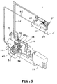
- a printing apparatus per se to be housed within a housing of the card printer is substantially the same as that shown in Fig. 10, a construction of the major portion is shown in Fig. 1 and a concept of an ink supply system thereof is illustrated in Fig. 5.
- the shown embodiment of the card printer includes a sub-tank 29 temporarily storing the ink to be supplied to the ink-jet head 21 and having an atmosphere communication aperture 28, a communication opening closing valve 30 for opening or closing the atmosphere communication opening 28 of the sub-tank 29, an ink supply tube 32 connecting the ink-jet head 21 and the sub-tank 29 and having a check valve 31 at the intermediate position thereof, a branched pipe 36 connected to the ink supply tube 32 at the position between the sub-tank 29 and the check valve 31 at one end and connected to a supply ink storage portion 34 of the ink cartridge 33 storing the ink at the other end, an ink supply pump 37 attached to the ink supply tube 32 at the position between a joining position of the branched tube 36 and the ink supply tube 32, which ink supply pump 37 can selectively supply the ink within the supply ink storage portion 34 of the ink cartridge 33 to the sub-tank 29 or the ink in the sub-tank 29 to the ink-jet head 21, an ink return tube 38
- the check valve 31 prevents backward flow the ink in the ink supply tube 32 from the ink-jet head 21 side to the ink supply tube 32.
- the check valve 35 serves for preventing backward flow of the ink within the ink supply tube 32 from the ink supply pump 37 side to the supply ink storage portion 34 of the ink cartridge 33.
- buffer tanks 42 and 43 for suppressing pulsation of the ink supply pump 37 and the ink circulating pump 41 are provided in the ink supply tube 32 between the ink-jet head 21 and the check valve 31 and the ink circulating tube 39 between the ink-jet head 21 and the ink circulating pump 41 are provided.
- a waste ink collection pump 47 for collecting a waste ink received in the capping member 22 to the waste ink storage portion 45 of the ink cartridge 33 under pressure.
- FIG. 6 An external appearance of a pump unit employed in the shown embodiment is shown in Fig. 6.
- FIG. 7 A construction of the ink supply pump 37 is shown in Fig. 7.
- the ink circulating pump 41 and the ink supply pump 37 have completely identical construction. Namely, these pumps 36, 41 and 47 are driven by a direct current motor 48.
- the ink supply pump 37 and the ink circulating pump 41 are controlled operation thereof via clutches 49 and 50, respectively.
- a pressure releasing cam 51 is driven by a not shown cam clutch and switches the ink supply pump 37 and the ink circulating pump 41 between active state and idling state via a pump retainer 52.
- the waste ink collection pump 47 is coupled with a direct current motor 48 via a not shown one-way clutch.
- the ink stored in the supply ink storage portion 34 of the ink cartridge 33 flows in a direction shown by an arrow a in the drawing, within the ink supply tube 32 from the branching tube 36 via the check valve 31 by revolution of the ink supply pump 37 in counterclockwise direction, and is stored in the sub-tank 29.
- the ink accumulated in the sub-tank 29 reaches a predetermined amount
- the ink flows in a direction of arrow b from the ink return tube 38 to be returned to the supply ink storage portion 34 of the ink cartridge 33.
- the communication opening closing valve 30 of the sub-tank 29 is placed in a condition closing the atmosphere communication opening 28.
- the ink accumulated in the sub-tank 29 flows in directions of arrows c and d within the ink supply tube 32 to be supplied the ink-jet head 21 via the buffer tank 42 and a connecting portion 56 through the check valve 31. Then, the ink circulated within the ink-jet head 21 flows in a direction of arrow e within the ink circulating tube 39 from the connecting portion 56 via a buffer tank 43, and again is returned to the sub-tank 29. At this time, the communication opening closing valve 30 of the sub-tank 29 is held in the opened condition.
- the recovery process of the shown embodiment is consisted of a normal cleaning process to be performed upon initiation of operation of the card printer, a second cleaning process to be performed in place of the normal cleaning only when the normal cleaning process is performed for a predetermined times, a recovery process to be performed immediately before formation of the image and a recovery process performed immediately after formation of the image.
- the pressure releasing cam 51 is switched into the engaging position by rotation over 180° from the release position shown in Fig. 7. Then, when the ink supply pump 37 is driven in the clockwise direction with disconnecting only clutch 50, the ink circulating tube 39 is placed in a condition closed by the ink circulating pump 41 to cause the ink within the sub-tank 29 to flow in the direction shown by arrows c and d to be discharged to an ink absorbing element 57 of the capping member 22 from the ejection opening 40 of the ink-jet head 21. At this time, the communication opening closing valve 30 of the sub-tank 29 is placed in the opened condition.
- the ink-jet head 21 is elevated to the wiping position to remove the ink droplet deposited on the ejection opening surface 44 by the wiping blade 23 (see Fig. 3). Then, the ink-jet head 21 is lowered again to the capping position.
- the pressure releasing cam 51 is returned to the release position shown in Fig. 7 to perform preliminary ejection, namely to eject the predetermined amount of ink droplet to the ink absorbing element 57 of the capping member 22 from the ejection opening 40 of the ink-jet head 21 in the same operation as that upon formation of the image.
- the waste ink thus received within the capping member 22 is collected in the waste ink storage portion 45 of the ink cartridge 33 by the waste ink collection pump 47.
- the ink circulating pump 41 is stopped by disengaging the clutch 50 to discharge the ink from the ejection opening 40 by revolution of only ink supply pump 37 to the ink absorbing element 57 of the capping member 22. At this time, the communication opening closing valve 30 of the sub-tank 29 is held in the open position.
- the ink-jet head 21 is elevated to the wiping position to remove the ink droplet deposited on the ejection opening surface 44 by the wiping blade 23. Then, the ink-jet head 21 is lowered again to the capping position, the pressure releasing cam 51 is returned to the release position shown in Fig. 7 to perform preliminary ejection.
- the ink ejected from the ejection opening 40 is received by the capping member 22 of the recovering unit 24 and is collected in the waste ink storage portion 45 of the ink cartridge 33 by the waste ink collection pump 47.
- preliminary ejection is performed by the ink-jet head 21 with maintaining the pressure releasing cam 51 in the release position at the capping position to receive the ink ejected from the ejection opening 40 by the capping member 22 of the recovering unit 24 to collect in the waste ink storage portion 45 of the ink cartridge 33 by the waste ink collection pump 47.
- the communication opening closing valve 30 of the sub-tank 29 is held in the open condition.
- the ink-jet head 21 is lowered to the image forming position to perform image forming process for the cut-sheet 20.
- the pressure releasing cam 51 is switched from the release position to the engaging position at the image forming position to elevate the ink-jet head 21 to the wiping position under the ink supply tube 32 and the ink circulating tube 39 are in closed condition to wipe the ejection opening surface 44 by the wiping blade 23 to remove the ink droplet deposited on the ejection opening surface 44.
- the ink-jet head 21 is lowered to the capping position to cover the ejection opening surface 44 by the capping member 22 and the pressure releasing cam 51 is switched to the release position to perform the preliminary ejection.
- the foregoing wiping operation and the preliminary ejection are repeated twice, respectively.
- the position of the ink surface or ink meniscus M formed in the ejection opening 40 of the ink-jet head 21 is not drawn into the ink passage 58 (see Figs. 4 and 11) by preventing flow of the ink by blocking the ink supply tube 32 and the ink circulating tube 39 to prevent suction of the foreign matter, such as dust and the like and the ink deposited in the vicinity of the ejection opening 40.
- the cut-sheet 20 is employed as the printing medium, any material and kind of the printing medium depending may be applicable adapting to mode of the image forming apparatus to be an object.
- the printing medium can be a perforated continuous paper which can be cut at the perforation, a sheet in a form of roll, on which labels on strippable paper are sequentially arranged, film, cloth and so on.
- the present invention achieves distinct effect when applied to an ink-jet apparatus which has means for generating thermal energy such as electrothermal transducers or laser light, and which causes changes in ink by the thermal energy so as to eject ink. This is because such a system can achieve a high density and high resolution image.
- the on-demand type apparatus has electrothermal transducers, each disposed on a sheet or liquid passage that retains liquid, and operates as follows: first, one or more drive signals are applied to the electrothermal transducers to cause thermal energy corresponding to printing information; second, the thermal energy induces sudden temperature rise that exceeds the nucleate boiling so as to cause the film boiling on heating portions of the ink-jet head; and third, bubbles are grown in liquid corresponding to the drive signals. By using the growth and collapse of the bubbles, the ink is expelled from at least one of the ink ejection openings of the ink-jet head to form one or more ink drops.
- the drive signal in the form of a pulse is preferable because the growth and collapse of the bubbles can be achieved instantaneously and suitably by this form of drive signal.
- a drive signal in the form of a pulse those described in U.S. patent Nos. 4,463,359 and 4,345,262 are preferable.
- the rate of temperature rise of the heating portions described in U.S. patent No. 4,313,124 be adopted to achieve better image forming.
- U.S. patent Nos. 4,558,333 and 4,459,600 disclose the following structure of an ink-jet head, which is incorporated to the present invention: this structure includes heating portions disposed on bent portions in addition to a combination of the ejection openings, liquid passages and the electrothermal transducers disclosed in the above patents. Moreover, the present invention can be applied to structures disclosed in Japanese Patent Application Laying-open Nos. 123670/1984 and 138461/1984 in order to achieve similar effects.
- the former discloses a structure in which a slit common to all the electrothermal transducers is used as ejection openings of the electrothermal transducers, and the latter discloses a structure in which openings for absorbing pressure waves caused by thermal energy are formed corresponding to the ejection openings.
- a preliminary auxiliary system for the ink-jet head as a constituent of the image forming apparatus because they serve to make the effect of the present invention more reliable.
- the preliminary auxiliary system are a preliminary heating means utilizing electrothermal transducers or a combination of other heater elements and the electrothermal transducers.
- the number and type of ink-jet heads to be mounted on the image forming apparatus can be also changed.
- only one ink-jet head corresponding to a single color ink, or a plurality of ink-jet heads corresponding to a plurality of inks different in color or concentration can be used.
- the present invention can be effectively applied to an apparatus having at least one of the monochromatic, multi-color and full-color modes.
- the monochromatic mode performs printing by using only one major color such as black.
- the multi-color mode carries out printing by using different color inks, and the full-color mode performs printing by color mixing. In this case, it is also effective to eject treatment liquid (printing ability enhancing liquid) for adjusting printing ability of the ink depending upon the printing medium.
- inks that are liquid when the recording signal is applied can be used: for example, inks can be employed that solidify at a temperature lower than the room temperature and are softened or liquefied in the room temperature.
- the present invention is most effective when it uses the film boiling phenomenon to expel the ink.
- the image forming apparatus of the present invention can be employed not only as an image output terminal of an information processing device such as a computer, but also as an output device of a copying machine including a reader, and as an output device of a facsimile or textile printing apparatus having a transmission and receiving function.
- the printing medium may be sheet form or elongated paper or cloth, or plate form wood, stone, resin, glass, metal, and in addition, three-dimensional structural member and so on.
- An image forming apparatus prevents foreign matter, such as dust or the like from being sucked into an ink passage from an ejection opening when a liquid ejection head ejecting a liquid is elevated from an image forming position to a recovery process position located above the image forming position.
- the image forming apparatus includes a liquid supply passage (39) connected to the liquid ejection head (21) which is provided with ejection opening (44) for ejecting liquid, liquid supply device (41) for supplying liquid to the liquid ejection head (21) via the liquid supply passage (39), recovery process device for recovering ejecting condition of liquid from the liquid ejection head (21), head moving device for moving the liquid ejection head between the recovery process position for performing recovery process of the liquid ejection head (21) by the recovery process device and an image forming position for forming an image on the printing medium by the liquid ejection head (21), and closing device (41) for closing the liquid supply passage (39) during movement of the liquid ejection head (21) into the recovery process position by the head moving device.
Landscapes
- Ink Jet (AREA)
Applications Claiming Priority (3)
| Application Number | Priority Date | Filing Date | Title |
|---|---|---|---|
| JP15345697 | 1997-06-11 | ||
| JP15345697 | 1997-06-11 | ||
| JP153456/97 | 1997-06-11 |
Publications (3)
| Publication Number | Publication Date |
|---|---|
| EP0884185A2 true EP0884185A2 (de) | 1998-12-16 |
| EP0884185A3 EP0884185A3 (de) | 1999-03-31 |
| EP0884185B1 EP0884185B1 (de) | 2002-10-16 |
Family
ID=15562962
Family Applications (1)
| Application Number | Title | Priority Date | Filing Date |
|---|---|---|---|
| EP19980110682 Expired - Lifetime EP0884185B1 (de) | 1997-06-11 | 1998-06-10 | Bilderzeugungsverfahren und Bilderzeugungsgerät dafür |
Country Status (2)
| Country | Link |
|---|---|
| EP (1) | EP0884185B1 (de) |
| DE (1) | DE69808696T2 (de) |
Cited By (4)
| Publication number | Priority date | Publication date | Assignee | Title |
|---|---|---|---|---|
| EP1231062A2 (de) * | 2001-02-09 | 2002-08-14 | Canon Kabushiki Kaisha | Flüssigkeitszuführvorrichtung, Tintenstrahlaufzeichnungskopf, Tintenstrahlaufzeichnungsapparat und Verfahren zum Befüllen mit einer Flüssigkeit |
| CN102343719A (zh) * | 2010-07-30 | 2012-02-08 | 兄弟工业株式会社 | 液体喷射设备 |
| CN104339871A (zh) * | 2013-07-30 | 2015-02-11 | 京瓷办公信息系统株式会社 | 流路开关装置以及具备该流路开关装置的喷墨记录装置 |
| US9028040B2 (en) | 2010-07-30 | 2015-05-12 | Brother Kogyo Kabushiki Kaisha | Liquid ejection apparatus and liquid ejection method |
Families Citing this family (1)
| Publication number | Priority date | Publication date | Assignee | Title |
|---|---|---|---|---|
| DE102018204794A1 (de) * | 2018-03-28 | 2019-10-02 | Weber Marking Systems Gmbh | Tintenstrahldruckeinheit |
Citations (6)
| Publication number | Priority date | Publication date | Assignee | Title |
|---|---|---|---|---|
| EP0376309A2 (de) * | 1988-12-30 | 1990-07-04 | Canon Kabushiki Kaisha | Tintenstrahlaufzeichnungsvorrichtung |
| EP0401026A2 (de) * | 1989-06-02 | 1990-12-05 | Canon Kabushiki Kaisha | Bildübertragungsvorrichtung |
| JPH06143554A (ja) * | 1992-11-07 | 1994-05-24 | Mita Ind Co Ltd | インクジェット記録装置 |
| US5534897A (en) * | 1993-07-01 | 1996-07-09 | Xerox Corporation | Ink jet maintenance subsystem |
| US5561448A (en) * | 1990-02-26 | 1996-10-01 | Canon Kabushiki Kaisha | Ink jet recording apparatus for recovering recording head |
| US5570117A (en) * | 1995-01-06 | 1996-10-29 | Tektronix, Inc. | Print head maintenance method and apparatus with retractable wiper |
-
1998
- 1998-06-10 DE DE1998608696 patent/DE69808696T2/de not_active Expired - Lifetime
- 1998-06-10 EP EP19980110682 patent/EP0884185B1/de not_active Expired - Lifetime
Patent Citations (6)
| Publication number | Priority date | Publication date | Assignee | Title |
|---|---|---|---|---|
| EP0376309A2 (de) * | 1988-12-30 | 1990-07-04 | Canon Kabushiki Kaisha | Tintenstrahlaufzeichnungsvorrichtung |
| EP0401026A2 (de) * | 1989-06-02 | 1990-12-05 | Canon Kabushiki Kaisha | Bildübertragungsvorrichtung |
| US5561448A (en) * | 1990-02-26 | 1996-10-01 | Canon Kabushiki Kaisha | Ink jet recording apparatus for recovering recording head |
| JPH06143554A (ja) * | 1992-11-07 | 1994-05-24 | Mita Ind Co Ltd | インクジェット記録装置 |
| US5534897A (en) * | 1993-07-01 | 1996-07-09 | Xerox Corporation | Ink jet maintenance subsystem |
| US5570117A (en) * | 1995-01-06 | 1996-10-29 | Tektronix, Inc. | Print head maintenance method and apparatus with retractable wiper |
Non-Patent Citations (1)
| Title |
|---|
| PATENT ABSTRACTS OF JAPAN vol. 018, no. 452 (M-1661), 23 August 1994 & JP 06 143554 A (MITA IND CO LTD), 24 May 1994 * |
Cited By (9)
| Publication number | Priority date | Publication date | Assignee | Title |
|---|---|---|---|---|
| EP1231062A2 (de) * | 2001-02-09 | 2002-08-14 | Canon Kabushiki Kaisha | Flüssigkeitszuführvorrichtung, Tintenstrahlaufzeichnungskopf, Tintenstrahlaufzeichnungsapparat und Verfahren zum Befüllen mit einer Flüssigkeit |
| EP1231062A3 (de) * | 2001-02-09 | 2003-06-04 | Canon Kabushiki Kaisha | Flüssigkeitszuführvorrichtung, Tintenstrahlaufzeichnungskopf, Tintenstrahlaufzeichnungsapparat und Verfahren zum Befüllen mit einer Flüssigkeit |
| US6805437B2 (en) | 2001-02-09 | 2004-10-19 | Canon Kabushiki Kaisha | Liquid supply system, ink jet recording head, ink jet recording apparatus and liquid filling method |
| CN102343719A (zh) * | 2010-07-30 | 2012-02-08 | 兄弟工业株式会社 | 液体喷射设备 |
| CN102343719B (zh) * | 2010-07-30 | 2014-08-20 | 兄弟工业株式会社 | 液体喷射设备 |
| US8998357B2 (en) | 2010-07-30 | 2015-04-07 | Brother Kogyo Kabushiki Kaisha | Liquid ejection apparatus |
| US9028040B2 (en) | 2010-07-30 | 2015-05-12 | Brother Kogyo Kabushiki Kaisha | Liquid ejection apparatus and liquid ejection method |
| CN104339871A (zh) * | 2013-07-30 | 2015-02-11 | 京瓷办公信息系统株式会社 | 流路开关装置以及具备该流路开关装置的喷墨记录装置 |
| CN104339871B (zh) * | 2013-07-30 | 2017-01-18 | 京瓷办公信息系统株式会社 | 流路开关装置以及具备该流路开关装置的喷墨记录装置 |
Also Published As
| Publication number | Publication date |
|---|---|
| DE69808696T2 (de) | 2003-03-13 |
| DE69808696D1 (de) | 2002-11-21 |
| EP0884185A3 (de) | 1999-03-31 |
| EP0884185B1 (de) | 2002-10-16 |
Similar Documents
| Publication | Publication Date | Title |
|---|---|---|
| US6491365B2 (en) | Image forming method and apparatus therefor | |
| JP2832776B2 (ja) | インクジェット記録装置 | |
| JP2005022193A (ja) | インクジェット記録装置 | |
| EP0931662A2 (de) | Tintenstrahldrucker und sein Steuerverfahren | |
| JP2009233972A (ja) | 液体吐出装置 | |
| JP3728195B2 (ja) | ヘッド回復装置及びヘッド回復方法並びにインクジェット記録装置 | |
| JP2000158673A (ja) | インクジェット式記録装置および同装置に用いられるフラッシング制御方法並びに制御装置 | |
| US6447096B1 (en) | Ink jet recording apparatus and recovery method therefor | |
| US6913339B2 (en) | Head recovery device, head recovery method and ink jet recording apparatus | |
| EP0884185B1 (de) | Bilderzeugungsverfahren und Bilderzeugungsgerät dafür | |
| JP2775034B2 (ja) | インクジェット記録装置 | |
| JP2004098475A (ja) | インクジェット記録装置 | |
| JP2805361B2 (ja) | 液体噴射記録装置 | |
| JPH07101081A (ja) | インクジェット記録装置 | |
| JP2009248430A (ja) | インクジェット記録装置、インクジェット記録方法、記録ヘッドの回復装置、および記録ヘッドの回復方法 | |
| JP2005022200A (ja) | インクジェット記録装置 | |
| JP3015188B2 (ja) | インクジェット記録装置 | |
| JPH06328731A (ja) | インクジェット記録装置 | |
| US20010024287A1 (en) | Printing apparatus and printing system | |
| JP2004074605A (ja) | インクジェット記録装置 | |
| JP3248544B2 (ja) | インクジェット記録装置 | |
| JP3241183B2 (ja) | インクジェット記録装置 | |
| JP2000015832A (ja) | インクジェット記録装置 | |
| JPH11254707A (ja) | インクジェット記録装置及びクリーニングユニット | |
| JP3025089B2 (ja) | インクジェット記録装置 |
Legal Events
| Date | Code | Title | Description |
|---|---|---|---|
| PUAI | Public reference made under article 153(3) epc to a published international application that has entered the european phase |
Free format text: ORIGINAL CODE: 0009012 |
|
| AK | Designated contracting states |
Kind code of ref document: A2 Designated state(s): DE FR GB IT |
|
| AX | Request for extension of the european patent |
Free format text: AL;LT;LV;MK;RO;SI |
|
| PUAL | Search report despatched |
Free format text: ORIGINAL CODE: 0009013 |
|
| AK | Designated contracting states |
Kind code of ref document: A3 Designated state(s): AT BE CH CY DE DK ES FI FR GB GR IE IT LI LU MC NL PT SE |
|
| AX | Request for extension of the european patent |
Free format text: AL;LT;LV;MK;RO;SI |
|
| 17P | Request for examination filed |
Effective date: 19990906 |
|
| AKX | Designation fees paid |
Free format text: DE FR GB IT |
|
| GRAG | Despatch of communication of intention to grant |
Free format text: ORIGINAL CODE: EPIDOS AGRA |
|
| 17Q | First examination report despatched |
Effective date: 20010530 |
|
| GRAG | Despatch of communication of intention to grant |
Free format text: ORIGINAL CODE: EPIDOS AGRA |
|
| GRAH | Despatch of communication of intention to grant a patent |
Free format text: ORIGINAL CODE: EPIDOS IGRA |
|
| GRAH | Despatch of communication of intention to grant a patent |
Free format text: ORIGINAL CODE: EPIDOS IGRA |
|
| GRAA | (expected) grant |
Free format text: ORIGINAL CODE: 0009210 |
|
| AK | Designated contracting states |
Kind code of ref document: B1 Designated state(s): DE FR GB IT |
|
| REG | Reference to a national code |
Ref country code: GB Ref legal event code: FG4D |
|
| REF | Corresponds to: |
Ref document number: 69808696 Country of ref document: DE Date of ref document: 20021121 |
|
| ET | Fr: translation filed | ||
| PLBE | No opposition filed within time limit |
Free format text: ORIGINAL CODE: 0009261 |
|
| STAA | Information on the status of an ep patent application or granted ep patent |
Free format text: STATUS: NO OPPOSITION FILED WITHIN TIME LIMIT |
|
| 26N | No opposition filed |
Effective date: 20030717 |
|
| REG | Reference to a national code |
Ref country code: FR Ref legal event code: CD |
|
| REG | Reference to a national code |
Ref country code: FR Ref legal event code: PLFP Year of fee payment: 19 |
|
| PGFP | Annual fee paid to national office [announced via postgrant information from national office to epo] |
Ref country code: GB Payment date: 20160608 Year of fee payment: 19 Ref country code: DE Payment date: 20160607 Year of fee payment: 19 |
|
| PGFP | Annual fee paid to national office [announced via postgrant information from national office to epo] |
Ref country code: FR Payment date: 20160516 Year of fee payment: 19 |
|
| PGFP | Annual fee paid to national office [announced via postgrant information from national office to epo] |
Ref country code: IT Payment date: 20160621 Year of fee payment: 19 |
|
| REG | Reference to a national code |
Ref country code: DE Ref legal event code: R119 Ref document number: 69808696 Country of ref document: DE |
|
| GBPC | Gb: european patent ceased through non-payment of renewal fee |
Effective date: 20170610 |
|
| REG | Reference to a national code |
Ref country code: FR Ref legal event code: ST Effective date: 20180228 |
|
| PG25 | Lapsed in a contracting state [announced via postgrant information from national office to epo] |
Ref country code: GB Free format text: LAPSE BECAUSE OF NON-PAYMENT OF DUE FEES Effective date: 20170610 Ref country code: DE Free format text: LAPSE BECAUSE OF NON-PAYMENT OF DUE FEES Effective date: 20180103 |
|
| PG25 | Lapsed in a contracting state [announced via postgrant information from national office to epo] |
Ref country code: IT Free format text: LAPSE BECAUSE OF NON-PAYMENT OF DUE FEES Effective date: 20170610 Ref country code: FR Free format text: LAPSE BECAUSE OF NON-PAYMENT OF DUE FEES Effective date: 20170630 |