EP0884104B1 - Disposable process device - Google Patents
Disposable process device Download PDFInfo
- Publication number
- EP0884104B1 EP0884104B1 EP98810205A EP98810205A EP0884104B1 EP 0884104 B1 EP0884104 B1 EP 0884104B1 EP 98810205 A EP98810205 A EP 98810205A EP 98810205 A EP98810205 A EP 98810205A EP 0884104 B1 EP0884104 B1 EP 0884104B1
- Authority
- EP
- European Patent Office
- Prior art keywords
- chamber
- process chamber
- pipetting
- array
- disposable
- Prior art date
- Legal status (The legal status is an assumption and is not a legal conclusion. Google has not performed a legal analysis and makes no representation as to the accuracy of the status listed.)
- Expired - Lifetime
Links
Images

Classifications
-
- B—PERFORMING OPERATIONS; TRANSPORTING
- B01—PHYSICAL OR CHEMICAL PROCESSES OR APPARATUS IN GENERAL
- B01L—CHEMICAL OR PHYSICAL LABORATORY APPARATUS FOR GENERAL USE
- B01L3/00—Containers or dishes for laboratory use, e.g. laboratory glassware; Droppers
- B01L3/50—Containers for the purpose of retaining a material to be analysed, e.g. test tubes
- B01L3/508—Containers for the purpose of retaining a material to be analysed, e.g. test tubes rigid containers not provided for above
-
- B—PERFORMING OPERATIONS; TRANSPORTING
- B01—PHYSICAL OR CHEMICAL PROCESSES OR APPARATUS IN GENERAL
- B01L—CHEMICAL OR PHYSICAL LABORATORY APPARATUS FOR GENERAL USE
- B01L9/00—Supporting devices; Holding devices
- B01L9/06—Test-tube stands; Test-tube holders
-
- Y—GENERAL TAGGING OF NEW TECHNOLOGICAL DEVELOPMENTS; GENERAL TAGGING OF CROSS-SECTIONAL TECHNOLOGIES SPANNING OVER SEVERAL SECTIONS OF THE IPC; TECHNICAL SUBJECTS COVERED BY FORMER USPC CROSS-REFERENCE ART COLLECTIONS [XRACs] AND DIGESTS
- Y10—TECHNICAL SUBJECTS COVERED BY FORMER USPC
- Y10T—TECHNICAL SUBJECTS COVERED BY FORMER US CLASSIFICATION
- Y10T436/00—Chemistry: analytical and immunological testing
- Y10T436/25—Chemistry: analytical and immunological testing including sample preparation
- Y10T436/2575—Volumetric liquid transfer
Definitions
- the invention relates to a disposable device for carrying out a process in which a biological sample is processed with one or more reagents said device including an integrally built array of chambers, a disposable pipetting tip and a parking chamber for parking therein said pipetting tip, said pipetting tip being configured and dimensioned to be at least partially inserted in the interior of the parking chamber.
- the invention relates in particular to a disposable device of this kind which is suitable for carrying out a process for obtaining a purified nucleic acid sample from a biological sample.
- the invention further relates to use of such a device for processing a fluid biological sample with one or more reagents in order to obtain a purified nucleic acid sample.
- PCR polymerase chain reaction
- a main object of the invention is to provide a device of the type indicated in the preamble so devised as to ensure a contamination-free automatic processing of samples and reagents to a degree which is sufficient to comply with the requirements of nucleic acid purification methods which provide nucleic acid samples having a high degree of purity and being thereby suitable to be amplified e.g. by a polymerase chain reaction (PCR).
- PCR polymerase chain reaction
- this aim is attained by means of a disposable process device which is characterized in that
- the above mentioned aim is attained by using a device according to the invention for carrying out a process wherein a fluid biological sample is processed with one or more reagents.
- This process comprises steps of automatic transfer of liquids from a process chamber to the waste chamber, or from a primary sample tube external to the device to the first process chamber, or from a process chamber to a specimen container external to the device, and wherein said transfer of liquids is effected by means of pipetting operations carried out exclusively with the disposable tip which is part of the device.
- the main advantage of the device and of the process according to the invention is that they make possible to ensure a contamination-free automatic processing of samples and reagents to a degree which is sufficient to comply with the requirements of nucleic acid purification methods which provide nucleic acid samples having a high degree of purity and being thereby suitable to be amplified e.g. by a polymerase chain reaction (PCR).
- PCR polymerase chain reaction
- a further advantage of the device according to the invention is that a plurality of these devices can be used simultaneously in an automatic apparatus to obtain a corresponding plurality of purified nucleic acid samples from respective biological samples.
- a specific advantage of an embodiment of the device according to the invention comprising only one process chamber is that it is cheaper than a device comprising more than one process chamber and that the small size of the device contributes to that less waste material has to be disposed of after use of the device and reduces also the cost of packaging material therefor.
- a preferred embodiment of the device according to the invention is characterized in that the cover comprises a first channel which provides access to the interior of the process chamber for dispensing a liquid into this chamber, this dispensing being effected with a pipetting cannula other than the disposable pipetting tip.
- the advantage of this embodiment is that the channel mentioned ensures that during the pipetting operation the tip of the pipetting cannula is located within a substantially closed environment which prevents accidental contamination during the transfer of liquid from the pipetting cannula to the process chamber.
- a further preferred embodiment of the device according to the invention is characterized in that a substantial part of the parking chamber is located within the waste chamber when said cover insert is inserted into said array of chambers. This configuration advantageously reduces the space occupied by the device, because no additional space is necessary for the parking chamber.
- Another preferred embodiment of the device according to the invention is characterized in that the process chamber depends freely downwardly from the bottom wall of said upper part of chamber array.
- This configuration offers the advantage that the lower part of the process chamber is accessible to external means, e.g. magnets, used to obtain separation of magnetic particles in suspension in a liquid contained in the process chamber.
- a further preferred embodiment of the device according to the invention is characterized in that said integrally built array of chambers further comprises a second process chamber having an open top end and a closed bottom end connected by a tubular wall which extends substantially perpendicular to the bottom wall of said upper part and downwardly from a third opening in said bottom wall, said third opening forming the open top end of the second process chamber.
- the advantage of this embodiment is that it offers more flexibility with regard to the sequence of process steps for carrying out a particular method. This flexibility is increased e.g. by maintaining the process chambers at different temperatures, e.g. one at 60° C and the other at 37° C, and/or by using one of the process chambers for provisional storage of a reagent before it is transferred to the other process chamber.
- a preferred embodiment of the device according to the invention and comprising 2 process chambers is characterized in that the bottom wall of said upper part comprises a second channel which provides access to the interior of the second process chamber for dispensing a liquid into this chamber, this dispensing being effected with a pipetting cannula other than the disposable pipetting tip.
- the advantage of this embodiment is that the second channel ensures that during the pipetting operation the tip of the pipetting cannula is located within a substantially closed environment which prevents accidental contamination during the transfer of liquid from the pipetting cannula to the second process chamber.
- Another preferred embodiment of the device according to the invention and comprising 2 process chambers is characterized in that the first process chamber, the waste chamber and the second process chamber are arranged in a row.
- This configuration advantageously simplifies the arrangement of a plurality of devices according to the invention in an automatic processing apparatus and also the transport means used for moving the disposable pipetting tip and the pipetting cannula to their pipetting positions with respect to the various chambers of the device.
- Another preferred embodiment of the device according to the invention and comprising 2 process chambers is characterized in that the waste chamber is located between the first process chamber and the second process chamber.
- This configuration advantageously reduces the motion paths of the disposable pipetting tip and the pipetting cannula necessary to bring these to their pipetting positions with respect to the various chambers of the device.
- a further preferred embodiment of the device according to the invention and comprising 2 process chambers is characterized in that the second process chamber depends freely downwardly from the bottom wall of said upper part of chamber array.
- This configuration offers the advantage that the lower part of the second process chamber is accessible to external means, e.g. magnets, used to obtain separation of magnetic particles in suspension in a liquid contained in the second process chamber.
- Preferred embodiments of the device according to the invention are characterized in that the array of chambers of the device according to the invention is a single piece of plastic material.
- Preferred embodiments of the device according to the invention are characterized in that said cover insert of the device according to the invention is a single piece of plastic material.
- a preferred use of the device according to the invention is for carrying out a process characterized in that it comprises steps of dispensing a liquid reagent from a reagent container external to the device into the process chamber, said dispensing being effected with a pipetting cannula other than the disposable tip which is part of the device.
- a preferred use of the device according to the invention and comprising 2 process chambers is for carrying out a process characterized in that it comprises steps of automatic transfer of liquids from the first process chamber into the second process chamber or vice versa, or from the first or the second process chamber to the waste chamber, or from a primary sample tube external to the device to the first or the second process chamber, or from the first or the second process chamber to a specimen container external to the device, and wherein said transfer of liquids is effected by means of pipetting operations carried out exclusively with the disposable tip which is part of the device.
- a further preferred use of the device according to the invention and comprising 2 process chambers is for carrying out a process characterized in that it comprises steps of dispensing a liquid reagent from a reagent container external to the device into the first process chamber and/or the second process chamber, said dispensing being effected with a pipetting cannula other than the disposable tip which is part of the device.
- a preferred use of the device according to the invention is for carrying out a process for isolating a nucleic acid contained in a biological sample.
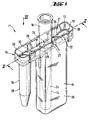
- Figures 1 to 3 show a first embodiment of a device 11 according to the invention.
- This first embodiment comprises an integrally built array of chambers 19, an integrally built cover insert 12 and a disposable pipetting tip 18.
- Array of chambers 19 and cover insert 12 are assembled together by inserting cover insert 12 into the upper part of array of chambers 19.
- Figures 1 and 2 show this assembly.
- Process chamber 26 has an open top end and a closed bottom end connected by a tubular wall 16 which extends substantially perpendicular to bottom wall 39 of the upper part of array of chambers 19 and downwardly from a first opening in bottom wall 39. This first opening forms the open top end of first process chamber 26. Process chamber 26 depends freely downwardly from the bottom wall 39 of the upper part of chamber array 19.
- Waste chamber 25 has an open top end and a closed bottom end connected by a side wall 15 which extends substantially perpendicular to bottom wall 39 of the upper part of array of chambers 19 and downwardly from a second opening in bottom wall 39. This second opening forms the open top end of waste chamber 25.
- Cover insert 12 is configured and dimensioned to be inserted in chamber array 19.
- Cover insert 12 comprises:
- cover 13 includes a jet deflector 23 which has the position shown in particular by Fig. 2 and which serves for deflecting a jet of liquid pipetted into waste chamber 25. Jet deflector 23 prevents that such a jet may impinge directly onto the free surface of liquid already contained in waste chamber 25. Such impact is undesirable, because in some cases it may cause splashing and expel some droplets out of waste chamber 25 through opening 35.
- Parking chamber 24 has an open top end and a closed bottom end connected by a tubular wall 14 which extends substantially perpendicular to cover 13 and downwardly from an opening 34 in cover 13. In a preferred embodiment the top end of tubular wall 14 of parking chamber 24 lies above cover 13.
- Disposable pipetting tip 18 is configured and dimensioned to be at least partially inserted in the interior of parking chamber 24.
- Disposable pipetting tip 18 has a tubular wall part of which snugly fits into the interior of parking chamber 24, the lower end of pipetting tip is kept however at some distance from the bottom and from the side walls of parking chamber 24.
- a filter 31 is located within the upper part of pipetting tip 18. Filter 31 serves to prevent contamination by carry-over of gas or liquid during pipetting operations.
- this array of tangs and the configuration and dimensions of the upper part of disposable pipetting tip 18 are so chosen that the top of the pipetting tip 18 or a couple of tangs, e.g. 21 and 22 or 28 and 29 can be gripped with the same gripper.
- parking chamber 24 is located within waste chamber 25 when cover insert 12 is inserted into array of chambers 19.
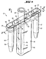
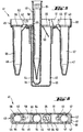
- FIGs 4 to 6 show a second embodiment of a device 41 according to the invention.
- This second embodiment comprises an integrally built array of chambers 49, an integrally built cover insert 42 and a disposable pipetting tip 48.
- Array of chambers 49 and cover insert 42 are assembled together by inserting cover insert 42 into the upper part of array of chambers 49.
- Figures 4 and 5 show this assembly.
- Process chamber 56 has an open top end and a closed bottom end connected by a tubular wall 46 which extends substantially perpendicular to bottom wall 69 of the upper part of array of chambers 49 and downwardly from a first opening 66 in bottom wall 69. This first opening forms the open top end of first process chamber 56.
- Process chamber 57 has an open top end and a closed bottom end connected by a tubular wall 47 which extends substantially perpendicular to bottom wall 69 of the upper part of array of chambers 49 and downwardly from a first opening in bottom wall 69. This first opening forms the open top end of process chamber 57.
- Process chamber 56 and process chamber 57 depend freely downwardly from the bottom wall 69 of the upper part of chamber array 49.
- Waste chamber 55 has an open top end and a closed bottom end connected by a side wall 45 which extends substantially perpendicular to bottom wall 69 of the upper part of array of chambers 49 and downwardly from a second opening in bottom wall 69. This second opening forms the open top end of waste chamber 55.
- Cover insert 42 is configured and dimensioned to be inserted in chamber array 49.
- Cover insert 42 comprises:
- cover 43 includes a jet deflector 53 which has the position shown in particular by Fig. 5 and which serves for deflecting a jet of liquid pipetted into waste chamber 55.
- Jet deflector 53 prevents that such a jet may impinge directly onto the free surface of liquid already contained in waste chamber 55. Such impact is undesirable, because in some cases it may cause splashing and expel some droplets out of waste chamber 55 through opening 65.
- Parking chamber 54 has an open top end and a closed bottom end connected by a tubular wall 44 which extends substantially perpendicular to cover 43 and downwardly from an opening 64 in cover 43.
- a tubular wall 44 of parking chamber 54 lies above cover 43.
- Disposable pipetting tip 48 is configured and dimensioned to be at least partially inserted in the interior of parking chamber 54.
- Disposable pipetting tip 48 has a tubular wall part of which snugly fits into the interior of parking chamber 54, the lower end of pipetting tip is kept however at some distance from the bottom and from the side walls of parking chamber 54.
- pipetting tip 48 is so configured and dimensioned that it can also be used as closure of the waste chamber 55 when the lower part of pipetting tip 48 is inserted through opening 65 into the waste chamber 55.
- cover insert 42 is such that it can be gripped and held by a suitable gripper (not shown) which is part of transport means of an automatic apparatus (not shown) so that cover insert 42 and thereby the entire device 41 can be moved by the gripper to different positions within the apparatus, e.g. from a parking position, where an array of devices 41 is positioned side by side, to an incubator position.
- a suitable gripper not shown
- cover insert 42 and thereby the entire device 41 can be moved by the gripper to different positions within the apparatus, e.g. from a parking position, where an array of devices 41 is positioned side by side, to an incubator position.
- cover insert 42 has an array of four tangs 51, 52, 58, 59 arranged as shown by the figures.
- this array of tangs and the configuration and dimensions of the upper part of disposable pipetting tip 48 are so chosen that the top of the pipetting tip 48 or a couple of tangs, e.g. 51 and 52 or 58 and 59 can be gripped with the same gripper.
- Cover 43 comprises a first channel 62 which provides access to the interior of the first process chamber 56 for pipetting into this chamber a reagent from a reagent container located outside device 41.
- Cover 43 further comprises a second channel 63 which provides access to the interior of the second process chamber 57 for pipetting into this chamber a reagent from a reagent container located outside device 41.
- This pipetting operations are effected with a pipetting cannula (not shown in the figures) other than disposable pipetting tip 48.
- parking chamber 54 is located within waste chamber 55 when cover insert 42 is inserted into array of chambers 49.
- first process chamber 56, the waste chamber 55 and the second process chamber 57 are arranged in a row.
- the waste chamber 55 is located between the first process chamber 56 and the second process chamber 57.
- Such a process comprises steps of automatic transfer of liquids from the process chamber 26 to the waste chamber 25, or from a primary sample tube external to the device to the process chamber 26, or from the first process chamber 26 to a specimen container external to the device.
- these transfers of liquids are effected by means of pipetting operations carried out exclusively with the disposable tip 18 which is part of the device 11, whereas steps of dispensing a liquid reagent from a reagent container external to the device into the first process chamber 26 are effected with a pipetting cannula other than the disposable tip 18 which is part of the device 11.
- Such a process comprises steps of automatic transfer of liquids from the first process chamber 56 into the second process 57 chamber or vice versa, or from the first or the second process chamber 56, 57 to the waste chamber 55, or from a primary sample tube external to the device to the first or the second process chamber 56, 57, or from the first or the second process chamber 56, 57 to a specimen container external to the device.
- these transfers of liquids are effected by means of pipetting operations carried out exclusively with the disposable tip 48 which is part of the device 41, whereas steps of dispensing a liquid reagent from a reagent container external to the device into the first process chamber 56 and/or the second process chamber 57 are effected with a pipetting cannula other than the disposable tip 48 which is part of the device 41.
- a preferred use of device 41 according to the invention is for carrying out a process for isolating a nucleic acid contained in a biological sample. Such a process comprises for instance the following steps:
Landscapes
- Health & Medical Sciences (AREA)
- Chemical & Material Sciences (AREA)
- Clinical Laboratory Science (AREA)
- Chemical Kinetics & Catalysis (AREA)
- Analytical Chemistry (AREA)
- General Health & Medical Sciences (AREA)
- Hematology (AREA)
- Automatic Analysis And Handling Materials Therefor (AREA)
- Apparatus Associated With Microorganisms And Enzymes (AREA)
- Investigating Or Analysing Materials By Optical Means (AREA)
- Investigating Or Analysing Biological Materials (AREA)
Priority Applications (1)
| Application Number | Priority Date | Filing Date | Title |
|---|---|---|---|
| EP98810205A EP0884104B1 (en) | 1997-06-09 | 1998-03-11 | Disposable process device |
Applications Claiming Priority (3)
| Application Number | Priority Date | Filing Date | Title |
|---|---|---|---|
| EP97109302 | 1997-06-09 | ||
| EP97109302 | 1997-06-09 | ||
| EP98810205A EP0884104B1 (en) | 1997-06-09 | 1998-03-11 | Disposable process device |
Publications (2)
| Publication Number | Publication Date |
|---|---|
| EP0884104A1 EP0884104A1 (en) | 1998-12-16 |
| EP0884104B1 true EP0884104B1 (en) | 2005-10-12 |
Family
ID=8226894
Family Applications (1)
| Application Number | Title | Priority Date | Filing Date |
|---|---|---|---|
| EP98810205A Expired - Lifetime EP0884104B1 (en) | 1997-06-09 | 1998-03-11 | Disposable process device |
Country Status (7)
| Country | Link |
|---|---|
| US (2) | US6063341A (enExample) |
| EP (1) | EP0884104B1 (enExample) |
| JP (1) | JP4056624B2 (enExample) |
| AT (1) | ATE306324T1 (enExample) |
| CA (1) | CA2233101C (enExample) |
| DE (1) | DE69831830T2 (enExample) |
| ES (1) | ES2249818T3 (enExample) |
Cited By (2)
| Publication number | Priority date | Publication date | Assignee | Title |
|---|---|---|---|---|
| US9513303B2 (en) | 2013-03-15 | 2016-12-06 | Abbott Laboratories | Light-blocking system for a diagnostic analyzer |
| US10577596B2 (en) | 2016-03-02 | 2020-03-03 | Roche Molecular Systems, Inc. | Device for separation |
Families Citing this family (70)
| Publication number | Priority date | Publication date | Assignee | Title |
|---|---|---|---|---|
| US6048734A (en) | 1995-09-15 | 2000-04-11 | The Regents Of The University Of Michigan | Thermal microvalves in a fluid flow method |
| ES2231589T3 (es) * | 1997-05-02 | 2005-05-16 | Gen-Probe Incorporated | Dispositivo con receptaculos de reaccion. |
| DE19963032A1 (de) | 1999-12-24 | 2001-06-28 | Roche Diagnostics Gmbh | System zur Bearbeitung von Proben in einer Mehrkammeranordnung |
| US6794193B2 (en) * | 2000-05-08 | 2004-09-21 | Arkray, Inc. | Method of assaying a specimen using a reagent |
| US7244392B1 (en) | 2000-05-22 | 2007-07-17 | Inverness Medical Switzerland Gmbh | Slide-in cassette for a cup for testing of drugs of abuse |
| US6576193B1 (en) | 2000-10-27 | 2003-06-10 | Shujie Cui | Device and method for collecting and testing fluid specimens |
| US6692700B2 (en) | 2001-02-14 | 2004-02-17 | Handylab, Inc. | Heat-reduction methods and systems related to microfluidic devices |
| US7010391B2 (en) | 2001-03-28 | 2006-03-07 | Handylab, Inc. | Methods and systems for control of microfluidic devices |
| US7829025B2 (en) | 2001-03-28 | 2010-11-09 | Venture Lending & Leasing Iv, Inc. | Systems and methods for thermal actuation of microfluidic devices |
| US6852287B2 (en) | 2001-09-12 | 2005-02-08 | Handylab, Inc. | Microfluidic devices having a reduced number of input and output connections |
| US8895311B1 (en) | 2001-03-28 | 2014-11-25 | Handylab, Inc. | Methods and systems for control of general purpose microfluidic devices |
| US7323140B2 (en) | 2001-03-28 | 2008-01-29 | Handylab, Inc. | Moving microdroplets in a microfluidic device |
| EP2407243B1 (en) | 2003-07-31 | 2020-04-22 | Handylab, Inc. | Multilayered microfluidic device |
| ES2553097T3 (es) | 2004-05-03 | 2015-12-04 | Handylab, Inc. | Procesamiento de muestras que contienen polinucleótidos |
| US8852862B2 (en) | 2004-05-03 | 2014-10-07 | Handylab, Inc. | Method for processing polynucleotide-containing samples |
| NZ620811A (en) | 2005-05-09 | 2015-09-25 | Theranos Inc | Point-of-care fluidic systems and uses thereof |
| US20070020151A1 (en) | 2005-07-20 | 2007-01-25 | Steven Woodside | Pipette tip holder |
| EP1767274B1 (en) * | 2005-09-26 | 2015-09-09 | QIAGEN GmbH | Method for processing a fluid |
| US8088616B2 (en) | 2006-03-24 | 2012-01-03 | Handylab, Inc. | Heater unit for microfluidic diagnostic system |
| US11806718B2 (en) | 2006-03-24 | 2023-11-07 | Handylab, Inc. | Fluorescence detector for microfluidic diagnostic system |
| US9040288B2 (en) | 2006-03-24 | 2015-05-26 | Handylab, Inc. | Integrated system for processing microfluidic samples, and method of using the same |
| US8883490B2 (en) | 2006-03-24 | 2014-11-11 | Handylab, Inc. | Fluorescence detector for microfluidic diagnostic system |
| US7998708B2 (en) * | 2006-03-24 | 2011-08-16 | Handylab, Inc. | Microfluidic system for amplifying and detecting polynucleotides in parallel |
| US10900066B2 (en) | 2006-03-24 | 2021-01-26 | Handylab, Inc. | Microfluidic system for amplifying and detecting polynucleotides in parallel |
| US8246919B2 (en) | 2006-09-21 | 2012-08-21 | Abbott Laboratories | Specimen sample rack |
| EP2091647A2 (en) | 2006-11-14 | 2009-08-26 | Handylab, Inc. | Microfluidic system for amplifying and detecting polynucleotides in parallel |
| US8133671B2 (en) | 2007-07-13 | 2012-03-13 | Handylab, Inc. | Integrated apparatus for performing nucleic acid extraction and diagnostic testing on multiple biological samples |
| USD621060S1 (en) | 2008-07-14 | 2010-08-03 | Handylab, Inc. | Microfluidic cartridge |
| ES2648798T3 (es) | 2007-07-13 | 2018-01-08 | Handylab, Inc. | Materiales de captura de polinucleótidos y métodos de utilización de los mismos |
| US8182763B2 (en) | 2007-07-13 | 2012-05-22 | Handylab, Inc. | Rack for sample tubes and reagent holders |
| US8287820B2 (en) | 2007-07-13 | 2012-10-16 | Handylab, Inc. | Automated pipetting apparatus having a combined liquid pump and pipette head system |
| US8105783B2 (en) | 2007-07-13 | 2012-01-31 | Handylab, Inc. | Microfluidic cartridge |
| US9186677B2 (en) | 2007-07-13 | 2015-11-17 | Handylab, Inc. | Integrated apparatus for performing nucleic acid extraction and diagnostic testing on multiple biological samples |
| AU2013205268B2 (en) * | 2007-07-13 | 2015-03-19 | Handylab, Inc. | Integrated apparatus for performing nucleic acid extraction and diagnostic testing on multiple biological samples |
| US9618139B2 (en) | 2007-07-13 | 2017-04-11 | Handylab, Inc. | Integrated heater and magnetic separator |
| US20090136385A1 (en) | 2007-07-13 | 2009-05-28 | Handylab, Inc. | Reagent Tube |
| MX352987B (es) * | 2007-10-02 | 2017-12-15 | Theranos Ip Co Llc | Dispositivos modulares de punto de cuidado y usos de los mismos. |
| USD618820S1 (en) | 2008-07-11 | 2010-06-29 | Handylab, Inc. | Reagent holder |
| USD787087S1 (en) | 2008-07-14 | 2017-05-16 | Handylab, Inc. | Housing |
| US20110308336A1 (en) * | 2010-06-16 | 2011-12-22 | Identigene, L.L.C. | Methods and apparatus for specimen collection and transport |
| CN103540517B (zh) * | 2010-07-23 | 2017-05-24 | 贝克曼考尔特公司 | 处理样本的系统及方法 |
| US9144801B2 (en) | 2010-08-31 | 2015-09-29 | Abbott Laboratories | Sample tube racks having retention bars |
| CA2825196C (en) | 2011-01-21 | 2021-01-05 | Theranos, Inc. | Systems and methods for sample use maximization |
| JP6088487B2 (ja) | 2011-04-15 | 2017-03-01 | ベクトン・ディキンソン・アンド・カンパニーBecton, Dickinson And Company | 走査リアルタイムマイクロ流体熱サイクラーと同期熱サイクリング及び走査光学検出の方法 |
| US9664702B2 (en) | 2011-09-25 | 2017-05-30 | Theranos, Inc. | Fluid handling apparatus and configurations |
| US9268915B2 (en) | 2011-09-25 | 2016-02-23 | Theranos, Inc. | Systems and methods for diagnosis or treatment |
| US8475739B2 (en) | 2011-09-25 | 2013-07-02 | Theranos, Inc. | Systems and methods for fluid handling |
| US8840838B2 (en) | 2011-09-25 | 2014-09-23 | Theranos, Inc. | Centrifuge configurations |
| US20140170735A1 (en) | 2011-09-25 | 2014-06-19 | Elizabeth A. Holmes | Systems and methods for multi-analysis |
| US9619627B2 (en) | 2011-09-25 | 2017-04-11 | Theranos, Inc. | Systems and methods for collecting and transmitting assay results |
| US9632102B2 (en) | 2011-09-25 | 2017-04-25 | Theranos, Inc. | Systems and methods for multi-purpose analysis |
| US10012664B2 (en) | 2011-09-25 | 2018-07-03 | Theranos Ip Company, Llc | Systems and methods for fluid and component handling |
| US9810704B2 (en) | 2013-02-18 | 2017-11-07 | Theranos, Inc. | Systems and methods for multi-analysis |
| US9250229B2 (en) | 2011-09-25 | 2016-02-02 | Theranos, Inc. | Systems and methods for multi-analysis |
| USD692162S1 (en) | 2011-09-30 | 2013-10-22 | Becton, Dickinson And Company | Single piece reagent holder |
| AU2012315595B2 (en) | 2011-09-30 | 2015-10-22 | Becton, Dickinson And Company | Unitized reagent strip |
| CN104040238B (zh) | 2011-11-04 | 2017-06-27 | 汉迪拉布公司 | 多核苷酸样品制备装置 |
| EP2607904B1 (en) * | 2011-12-21 | 2020-01-15 | Roche Diagnostics GmbH | Method for disposing of a liquid within an automated analytical system, tip rack assembly and analytical system |
| USD672882S1 (en) * | 2012-01-18 | 2012-12-18 | Beckman Coulter, Inc. | Cartridge for extraction or purification |
| USD672881S1 (en) * | 2012-01-18 | 2012-12-18 | Beckman Coulter, Inc. | Reagent pack |
| JP6262152B2 (ja) | 2012-02-03 | 2018-01-17 | ベクトン・ディキンソン・アンド・カンパニーBecton, Dickinson And Company | 分子診断試験の分布及び試験間のコンパチビリティ判断のための外部ファイル |
| EP2703820B1 (en) | 2012-08-31 | 2019-08-28 | F. Hoffmann-La Roche AG | Mobile tip waste rack |
| AU2013202778A1 (en) | 2013-03-14 | 2014-10-02 | Gen-Probe Incorporated | Systems, methods, and apparatuses for performing automated reagent-based assays |
| US9993820B2 (en) | 2013-03-15 | 2018-06-12 | Abbott Laboratories | Automated reagent manager of a diagnostic analyzer system |
| WO2014144759A1 (en) | 2013-03-15 | 2014-09-18 | Abbott Laboratories | Linear track diagnostic analyzer |
| USD703266S1 (en) * | 2013-07-01 | 2014-04-22 | Target Brands, Inc. | Desk caddy |
| US11545241B1 (en) | 2013-09-07 | 2023-01-03 | Labrador Diagnostics Llc | Systems and methods for analyte testing and data management |
| USD814653S1 (en) | 2014-08-07 | 2018-04-03 | Becton, Dickinson And Company | Sample tube holder and components thereof |
| US12109568B2 (en) | 2018-01-23 | 2024-10-08 | Roche Molecular Systems, Inc. | Tube tray for secondary tubes, secondary tube handling module, and method of handling secondary tubes in an automated processing system |
| USD957679S1 (en) * | 2018-12-28 | 2022-07-12 | Delta Electronics, Inc. | Extraction cartridge |
Family Cites Families (17)
| Publication number | Priority date | Publication date | Assignee | Title |
|---|---|---|---|---|
| US3785773A (en) * | 1972-03-02 | 1974-01-15 | Beckman Instruments Inc | Chemical analysis tube module |
| US4287155A (en) * | 1980-06-16 | 1981-09-01 | Eastman Kodak Company | Sample tray and carrier for chemical analyzer |
| US4391780A (en) * | 1981-07-06 | 1983-07-05 | Beckman Instruments, Inc. | Container for sample testing |
| SU1671531A1 (ru) * | 1988-10-20 | 1991-08-23 | Харьковский научно-исследовательский институт терапии | Устройство дл хранени биологических жидкостей |
| IL94408A0 (en) * | 1989-07-11 | 1991-03-10 | Miles Inc | Method,reaction cassette and kit for performing analytical assays |
| GB2243446B (en) * | 1990-04-25 | 1994-05-25 | Pfizer Ltd | An assay tray and assembly |
| CA2062808A1 (en) * | 1990-05-01 | 1991-11-02 | Harry E. Petschek | Integral biomolecule preparation device |
| JPH0675497B2 (ja) * | 1990-11-15 | 1994-09-28 | 倉敷紡績株式会社 | プラスミド分離装置 |
| JPH074220B2 (ja) * | 1991-01-16 | 1995-01-25 | 倉敷紡績株式会社 | プラスミド自動分離装置 |
| SE503729C2 (sv) * | 1991-03-11 | 1996-08-12 | Mats Malmquist | Extraktionssystem |
| FR2678950B1 (fr) * | 1991-07-09 | 1993-11-05 | Bertin Et Cie | Cartouche, dispositif et procede d'extraction d'acides nucleiques tels que l'adn a partir d'un echantillon de sang ou de cellules de tissus. |
| US5438128A (en) * | 1992-02-07 | 1995-08-01 | Millipore Corporation | Method for rapid purifiction of nucleic acids using layered ion-exchange membranes |
| US5330439A (en) * | 1992-04-08 | 1994-07-19 | American National Red Cross | Safety device for use in collecting fluid samples |
| EP1245286B1 (en) * | 1993-10-22 | 2009-11-25 | Abbott Laboratories | Reaction tube and method of use to minimize contamination |
| US5609822A (en) * | 1995-07-07 | 1997-03-11 | Ciba Corning Diagnostics Corp. | Reagent handling system and reagent pack for use therein |
| DE69637047T2 (de) * | 1995-07-13 | 2007-12-27 | Applera Corp., Foster City | Unabhängiges gerät zur extraktion, amplifikation und nachweis von nukleinsäuren |
| CA2226776C (en) * | 1995-07-31 | 2007-11-27 | Hideji Tajima | Multi-vessel container for testing fluids |
-
1998
- 1998-03-11 DE DE69831830T patent/DE69831830T2/de not_active Expired - Lifetime
- 1998-03-11 AT AT98810205T patent/ATE306324T1/de active
- 1998-03-11 EP EP98810205A patent/EP0884104B1/en not_active Expired - Lifetime
- 1998-03-11 ES ES98810205T patent/ES2249818T3/es not_active Expired - Lifetime
- 1998-04-01 CA CA002233101A patent/CA2233101C/en not_active Expired - Fee Related
- 1998-05-15 JP JP13325798A patent/JP4056624B2/ja not_active Expired - Lifetime
- 1998-06-09 US US09/093,776 patent/US6063341A/en not_active Expired - Lifetime
-
2000
- 2000-02-22 US US09/510,924 patent/US6506610B1/en not_active Expired - Lifetime
Cited By (2)
| Publication number | Priority date | Publication date | Assignee | Title |
|---|---|---|---|---|
| US9513303B2 (en) | 2013-03-15 | 2016-12-06 | Abbott Laboratories | Light-blocking system for a diagnostic analyzer |
| US10577596B2 (en) | 2016-03-02 | 2020-03-03 | Roche Molecular Systems, Inc. | Device for separation |
Also Published As
| Publication number | Publication date |
|---|---|
| DE69831830D1 (de) | 2006-02-23 |
| ES2249818T3 (es) | 2006-04-01 |
| JPH119258A (ja) | 1999-01-19 |
| EP0884104A1 (en) | 1998-12-16 |
| DE69831830T2 (de) | 2006-06-22 |
| JP4056624B2 (ja) | 2008-03-05 |
| CA2233101A1 (en) | 1998-12-09 |
| CA2233101C (en) | 2006-12-05 |
| US6506610B1 (en) | 2003-01-14 |
| ATE306324T1 (de) | 2005-10-15 |
| US6063341A (en) | 2000-05-16 |
Similar Documents
| Publication | Publication Date | Title |
|---|---|---|
| EP0884104B1 (en) | Disposable process device | |
| EP2333559B1 (en) | Nucleic acid analysis method and automated nucleic acid analyzer with spatial separation | |
| US6921513B2 (en) | System for processing samples in a multichamber arrangement | |
| EP2192186B1 (en) | System and method for the automated extraction of nucleic acids | |
| EP0843176B1 (en) | Analysis system comprising a container and a liquid sucking/discharging line | |
| EP1577675B1 (en) | Apparatus and method for handling fluids for analysis | |
| EP1340982B1 (en) | Assay work station | |
| EP2338597B1 (en) | Multiwell plate and lid | |
| US10351843B2 (en) | System for separating and detecting an analyte | |
| EP2338600B1 (en) | Process head positioning | |
| EP2338596B1 (en) | Tip rack | |
| JPH119258A5 (enExample) | ||
| EP2629098B1 (en) | Workflow timing between modules | |
| US10101354B2 (en) | Method for prevention of contamination during disposing of liquid by pipet array | |
| EP2333558B1 (en) | Form-locking gripping system | |
| US4673653A (en) | Method of performing biological analyses using immunological reactions, and apparatus for performing the method | |
| CA2737955A1 (en) | Automated diagnostic analyzer and method | |
| CN103959070A (zh) | 组合试剂条 | |
| JP5846773B2 (ja) | サンプルの分配 | |
| CN112384300A (zh) | 药筒、电润湿样品处理系统和珠粒操纵方法 |
Legal Events
| Date | Code | Title | Description |
|---|---|---|---|
| PUAI | Public reference made under article 153(3) epc to a published international application that has entered the european phase |
Free format text: ORIGINAL CODE: 0009012 |
|
| AK | Designated contracting states |
Kind code of ref document: A1 Designated state(s): AT BE CH DE DK ES FR GB IT LI NL |
|
| AX | Request for extension of the european patent |
Free format text: AL;LT;LV;MK;RO;SI |
|
| 17P | Request for examination filed |
Effective date: 19990517 |
|
| AKX | Designation fees paid |
Free format text: AT BE CH DE DK ES FR GB IT LI NL |
|
| 17Q | First examination report despatched |
Effective date: 20011121 |
|
| GRAP | Despatch of communication of intention to grant a patent |
Free format text: ORIGINAL CODE: EPIDOSNIGR1 |
|
| GRAS | Grant fee paid |
Free format text: ORIGINAL CODE: EPIDOSNIGR3 |
|
| GRAA | (expected) grant |
Free format text: ORIGINAL CODE: 0009210 |
|
| AK | Designated contracting states |
Kind code of ref document: B1 Designated state(s): AT BE CH DE DK ES FR GB IT LI NL |
|
| REG | Reference to a national code |
Ref country code: GB Ref legal event code: FG4D |
|
| REG | Reference to a national code |
Ref country code: CH Ref legal event code: EP |
|
| REG | Reference to a national code |
Ref country code: CH Ref legal event code: NV Representative=s name: VENTOCILLA PATENT AG |
|
| PG25 | Lapsed in a contracting state [announced via postgrant information from national office to epo] |
Ref country code: DK Free format text: LAPSE BECAUSE OF FAILURE TO SUBMIT A TRANSLATION OF THE DESCRIPTION OR TO PAY THE FEE WITHIN THE PRESCRIBED TIME-LIMIT Effective date: 20060112 |
|
| REF | Corresponds to: |
Ref document number: 69831830 Country of ref document: DE Date of ref document: 20060223 Kind code of ref document: P |
|
| REG | Reference to a national code |
Ref country code: ES Ref legal event code: FG2A Ref document number: 2249818 Country of ref document: ES Kind code of ref document: T3 |
|
| ET | Fr: translation filed | ||
| PLBE | No opposition filed within time limit |
Free format text: ORIGINAL CODE: 0009261 |
|
| STAA | Information on the status of an ep patent application or granted ep patent |
Free format text: STATUS: NO OPPOSITION FILED WITHIN TIME LIMIT |
|
| 26N | No opposition filed |
Effective date: 20060713 |
|
| REG | Reference to a national code |
Ref country code: CH Ref legal event code: NV Representative=s name: ROCHE DIAGNOSTICS AG |
|
| PGFP | Annual fee paid to national office [announced via postgrant information from national office to epo] |
Ref country code: IT Payment date: 20120321 Year of fee payment: 15 |
|
| REG | Reference to a national code |
Ref country code: CH Ref legal event code: PFA Owner name: F. HOFFMANN-LA ROCHE AG, CH Free format text: FORMER OWNER: F. HOFFMANN-LA ROCHE AG, CH |
|
| PGFP | Annual fee paid to national office [announced via postgrant information from national office to epo] |
Ref country code: ES Payment date: 20130313 Year of fee payment: 16 Ref country code: CH Payment date: 20130129 Year of fee payment: 16 |
|
| PGFP | Annual fee paid to national office [announced via postgrant information from national office to epo] |
Ref country code: AT Payment date: 20130225 Year of fee payment: 16 |
|
| PGFP | Annual fee paid to national office [announced via postgrant information from national office to epo] |
Ref country code: BE Payment date: 20130410 Year of fee payment: 16 |
|
| PGFP | Annual fee paid to national office [announced via postgrant information from national office to epo] |
Ref country code: NL Payment date: 20130312 Year of fee payment: 16 |
|
| REG | Reference to a national code |
Ref country code: NL Ref legal event code: V1 Effective date: 20141001 |
|
| REG | Reference to a national code |
Ref country code: CH Ref legal event code: PL |
|
| REG | Reference to a national code |
Ref country code: AT Ref legal event code: MM01 Ref document number: 306324 Country of ref document: AT Kind code of ref document: T Effective date: 20140311 |
|
| PG25 | Lapsed in a contracting state [announced via postgrant information from national office to epo] |
Ref country code: CH Free format text: LAPSE BECAUSE OF NON-PAYMENT OF DUE FEES Effective date: 20140331 Ref country code: LI Free format text: LAPSE BECAUSE OF NON-PAYMENT OF DUE FEES Effective date: 20140331 |
|
| PG25 | Lapsed in a contracting state [announced via postgrant information from national office to epo] |
Ref country code: NL Free format text: LAPSE BECAUSE OF NON-PAYMENT OF DUE FEES Effective date: 20141001 Ref country code: AT Free format text: LAPSE BECAUSE OF NON-PAYMENT OF DUE FEES Effective date: 20140311 |
|
| PG25 | Lapsed in a contracting state [announced via postgrant information from national office to epo] |
Ref country code: IT Free format text: LAPSE BECAUSE OF NON-PAYMENT OF DUE FEES Effective date: 20140311 |
|
| REG | Reference to a national code |
Ref country code: ES Ref legal event code: FD2A Effective date: 20150424 |
|
| PG25 | Lapsed in a contracting state [announced via postgrant information from national office to epo] |
Ref country code: ES Free format text: LAPSE BECAUSE OF NON-PAYMENT OF DUE FEES Effective date: 20140312 |
|
| REG | Reference to a national code |
Ref country code: FR Ref legal event code: PLFP Year of fee payment: 19 |
|
| REG | Reference to a national code |
Ref country code: FR Ref legal event code: PLFP Year of fee payment: 20 |
|
| PGFP | Annual fee paid to national office [announced via postgrant information from national office to epo] |
Ref country code: FR Payment date: 20170222 Year of fee payment: 20 |
|
| PGFP | Annual fee paid to national office [announced via postgrant information from national office to epo] |
Ref country code: GB Payment date: 20170223 Year of fee payment: 20 |
|
| PG25 | Lapsed in a contracting state [announced via postgrant information from national office to epo] |
Ref country code: BE Free format text: LAPSE BECAUSE OF NON-PAYMENT OF DUE FEES Effective date: 20140331 |
|
| PGFP | Annual fee paid to national office [announced via postgrant information from national office to epo] |
Ref country code: DE Payment date: 20170331 Year of fee payment: 20 |
|
| REG | Reference to a national code |
Ref country code: DE Ref legal event code: R071 Ref document number: 69831830 Country of ref document: DE |
|
| REG | Reference to a national code |
Ref country code: GB Ref legal event code: PE20 Expiry date: 20180310 |
|
| PG25 | Lapsed in a contracting state [announced via postgrant information from national office to epo] |
Ref country code: GB Free format text: LAPSE BECAUSE OF EXPIRATION OF PROTECTION Effective date: 20180310 |