EP0881441A2 - Dispositif d'alimentation en air réfrigéré pour réfrigérateur - Google Patents
Dispositif d'alimentation en air réfrigéré pour réfrigérateur Download PDFInfo
- Publication number
- EP0881441A2 EP0881441A2 EP98108545A EP98108545A EP0881441A2 EP 0881441 A2 EP0881441 A2 EP 0881441A2 EP 98108545 A EP98108545 A EP 98108545A EP 98108545 A EP98108545 A EP 98108545A EP 0881441 A2 EP0881441 A2 EP 0881441A2
- Authority
- EP
- European Patent Office
- Prior art keywords
- refrigerated air
- door
- duct
- fresh food
- supply apparatus
- Prior art date
- Legal status (The legal status is an assumption and is not a legal conclusion. Google has not performed a legal analysis and makes no representation as to the accuracy of the status listed.)
- Granted
Links
Images


Classifications
-
- F—MECHANICAL ENGINEERING; LIGHTING; HEATING; WEAPONS; BLASTING
- F25—REFRIGERATION OR COOLING; COMBINED HEATING AND REFRIGERATION SYSTEMS; HEAT PUMP SYSTEMS; MANUFACTURE OR STORAGE OF ICE; LIQUEFACTION SOLIDIFICATION OF GASES
- F25D—REFRIGERATORS; COLD ROOMS; ICE-BOXES; COOLING OR FREEZING APPARATUS NOT OTHERWISE PROVIDED FOR
- F25D17/00—Arrangements for circulating cooling fluids; Arrangements for circulating gas, e.g. air, within refrigerated spaces
- F25D17/04—Arrangements for circulating cooling fluids; Arrangements for circulating gas, e.g. air, within refrigerated spaces for circulating air, e.g. by convection
- F25D17/06—Arrangements for circulating cooling fluids; Arrangements for circulating gas, e.g. air, within refrigerated spaces for circulating air, e.g. by convection by forced circulation
- F25D17/062—Arrangements for circulating cooling fluids; Arrangements for circulating gas, e.g. air, within refrigerated spaces for circulating air, e.g. by convection by forced circulation in household refrigerators
- F25D17/065—Arrangements for circulating cooling fluids; Arrangements for circulating gas, e.g. air, within refrigerated spaces for circulating air, e.g. by convection by forced circulation in household refrigerators with compartments at different temperatures
-
- F—MECHANICAL ENGINEERING; LIGHTING; HEATING; WEAPONS; BLASTING
- F25—REFRIGERATION OR COOLING; COMBINED HEATING AND REFRIGERATION SYSTEMS; HEAT PUMP SYSTEMS; MANUFACTURE OR STORAGE OF ICE; LIQUEFACTION SOLIDIFICATION OF GASES
- F25D—REFRIGERATORS; COLD ROOMS; ICE-BOXES; COOLING OR FREEZING APPARATUS NOT OTHERWISE PROVIDED FOR
- F25D23/00—General constructional features
- F25D23/02—Doors; Covers
- F25D23/028—Details
-
- F—MECHANICAL ENGINEERING; LIGHTING; HEATING; WEAPONS; BLASTING
- F25—REFRIGERATION OR COOLING; COMBINED HEATING AND REFRIGERATION SYSTEMS; HEAT PUMP SYSTEMS; MANUFACTURE OR STORAGE OF ICE; LIQUEFACTION SOLIDIFICATION OF GASES
- F25D—REFRIGERATORS; COLD ROOMS; ICE-BOXES; COOLING OR FREEZING APPARATUS NOT OTHERWISE PROVIDED FOR
- F25D2317/00—Details or arrangements for circulating cooling fluids; Details or arrangements for circulating gas, e.g. air, within refrigerated spaces, not provided for in other groups of this subclass
- F25D2317/06—Details or arrangements for circulating cooling fluids; Details or arrangements for circulating gas, e.g. air, within refrigerated spaces, not provided for in other groups of this subclass with forced air circulation
- F25D2317/062—Details or arrangements for circulating cooling fluids; Details or arrangements for circulating gas, e.g. air, within refrigerated spaces, not provided for in other groups of this subclass with forced air circulation along the inside of doors
-
- F—MECHANICAL ENGINEERING; LIGHTING; HEATING; WEAPONS; BLASTING
- F25—REFRIGERATION OR COOLING; COMBINED HEATING AND REFRIGERATION SYSTEMS; HEAT PUMP SYSTEMS; MANUFACTURE OR STORAGE OF ICE; LIQUEFACTION SOLIDIFICATION OF GASES
- F25D—REFRIGERATORS; COLD ROOMS; ICE-BOXES; COOLING OR FREEZING APPARATUS NOT OTHERWISE PROVIDED FOR
- F25D2317/00—Details or arrangements for circulating cooling fluids; Details or arrangements for circulating gas, e.g. air, within refrigerated spaces, not provided for in other groups of this subclass
- F25D2317/06—Details or arrangements for circulating cooling fluids; Details or arrangements for circulating gas, e.g. air, within refrigerated spaces, not provided for in other groups of this subclass with forced air circulation
- F25D2317/065—Details or arrangements for circulating cooling fluids; Details or arrangements for circulating gas, e.g. air, within refrigerated spaces, not provided for in other groups of this subclass with forced air circulation characterised by the air return
- F25D2317/0653—Details or arrangements for circulating cooling fluids; Details or arrangements for circulating gas, e.g. air, within refrigerated spaces, not provided for in other groups of this subclass with forced air circulation characterised by the air return through the mullion
-
- F—MECHANICAL ENGINEERING; LIGHTING; HEATING; WEAPONS; BLASTING
- F25—REFRIGERATION OR COOLING; COMBINED HEATING AND REFRIGERATION SYSTEMS; HEAT PUMP SYSTEMS; MANUFACTURE OR STORAGE OF ICE; LIQUEFACTION SOLIDIFICATION OF GASES
- F25D—REFRIGERATORS; COLD ROOMS; ICE-BOXES; COOLING OR FREEZING APPARATUS NOT OTHERWISE PROVIDED FOR
- F25D2400/00—General features of, or devices for refrigerators, cold rooms, ice-boxes, or for cooling or freezing apparatus not covered by any other subclass
- F25D2400/04—Refrigerators with a horizontal mullion
-
- F—MECHANICAL ENGINEERING; LIGHTING; HEATING; WEAPONS; BLASTING
- F25—REFRIGERATION OR COOLING; COMBINED HEATING AND REFRIGERATION SYSTEMS; HEAT PUMP SYSTEMS; MANUFACTURE OR STORAGE OF ICE; LIQUEFACTION SOLIDIFICATION OF GASES
- F25D—REFRIGERATORS; COLD ROOMS; ICE-BOXES; COOLING OR FREEZING APPARATUS NOT OTHERWISE PROVIDED FOR
- F25D2700/00—Means for sensing or measuring; Sensors therefor
- F25D2700/12—Sensors measuring the inside temperature
- F25D2700/123—Sensors measuring the inside temperature more than one sensor measuring the inside temperature in a compartment
Definitions
- This invention relates to a refrigerator, and more particularly a refrigerated air supply apparatus for providing a portion of refrigerated air rearward from the door of the refrigerator.
- Figs. 1 and 2 generally refrigerators have a freezer compartment 10 and a fresh food compartment 20 partitioned by an insulation barrier 5.
- the compartments 10, 20 is defined by inner cases 12, 22 respectively surrounded by insulation 7 which is cased by outer case 2.
- a fan unit 4 which is for providing refrigerated air flow path to both freezer compartment 10 and fresh food compartment 20 is mounted in a evaporating chamber 11 provided at the rear of the freezer compartment 10.
- An evaporator 8 is also provided in the evaporating chamber 11 in which refrigerated air is generated thereby.
- the compartments 10, 20 is closed by doors 19, 29 which are hinged in front of the refrigerator.
- the door 29 have door baskets 26 mounted at inner surfaces thereof for storing food therein.
- Refrigerated air supplied to fresh food compartment 20 via above-mentioned supply path then moves forward and carries out heat exchanges with food stored in fresh food compartment 20, thereby being relatively warmed air.
- the warmed air returns to the evaporating chamber 11 through a return duct 30 formed in the insulation barrier 5 with its inlet 31 adjacent to the door 29.
- the warmed air in the evaporating chamber 11 carries out heat exchanges with the evaporator 8, thereby being refrigerated air repeatedly.
- the conventional refrigerated air circulation system has a number of short comings. First, it reduces the effective uniform cooling of the fresh food compartment 20, since the refrigerated air is provided only one direction, forward, from the outlets 25 of fresh food duct 24. This means that the temperature of a portion adjacent to the outlets 25 is lower than that of a portion adjacent to the door 29. Therefore, food stored adjacent to the outlets 25 may be over-refrigerated while food stored adjacent to the door 29 is tend to be perishable due to relative high temperature. This problem is based on the fact that the refrigerated air is provided into the fresh food compartment 20 only one direction from the duct 24. Second, the temperature of door adjacent portion in the fresh food compartment 20 tent to be increased due to frequent opening of the door 29.
- a problem with the circulation system is that the transmission duct occupies a certain space in the fresh food compartment where food is stored so that the substantial storage space in fresh food compartment is restricted by the presence of transmission duct.
- Another problem is that the amount of refrigerated air spouted by the door duct is not sufficient, since the delivered refrigerated air through the transmission duct is the one which had been provided to the cool air duct.
- This problem can be overcome by a circulation system which delivers refrigerated air from evaporating chamber directly to the door duct, without via the cool air duct.
- Still another problem is that the temperature difference between the fresh food compartment and interior of the transmission duct conduct to dewing and freezing on the surface of the transmission duct.
- a refrigerated air supply apparatus includes a means for generating refrigerated air, a passageway for guiding the refrigerated air through the insulating layer, a fresh food duct for providing refrigerated air into the fresh food compartment from said passageway, a connecting duct diverged from the passageway in the insulation layer and extends forward to the front of the fresh food compartment in insulated state, and a door duct mounted in the door for spouting refrigerated air which is delivered through said connecting duct into the fresh food compartment rearward.
- a refrigerated air supply apparatus includes a means for generating refrigerated air, a passageway for guiding the refrigerated air through the insulating layer, a fresh food duct for providing refrigerated air into the fresh food compartment from said passageway, a connecting duct diverged from the uppermost of fresh food duct and extends forward to the front of the fresh food compartment, and a door duct mounted in the door for spouting refrigerated air which is delivered through said connecting duct into the fresh food compartment rearward.
- a refrigerator of the invention have a freezer compartment 110 and a fresh food compartment 120 partitioned by an insulation barrier 134.
- a refrigerated air supply apparatus of the invention includes a connecting duct 132 which is diverged from a passageway 130 in the insulation barrier 134.
- the connecting duct 132 provides the refrigerated air to a door duct 160 mounted in a door 150 so that the door duct 160 flows refrigerated air into the fresh food compartment 120 rearward, thereby achieving uniform cooling of the fresh food compartment 120.
- the passageway 130 means a duct or a path which flows refrigerated air from a refrigerating chamber 111 to the fresh food compartment 120, including all conventional ones.
- the connecting duct 132 is diverged in the interior of the insulation barrier 134. Being diverged from the passageway 130 in the barrier 134, connecting duct 132 extends forward and has an outlet 133 on the front portion of lower wall 134a of the barrier 134. The outlet 133 of the connecting duct 132 is adjacent to a door 150 which close the fresh food compartment 120. Since connecting duct 132 is mounted in the interior of the barrier 134, it does not occupy any space in the fresh food compartment 120. The storage space, therefore, in the fresh food compartment 120 can be fully utilized.
- a door duct 160 is mounted in the door 150 which receives refrigerated air from the passageway 130 through the connecting duct 132.
- the door duct 160 have an inlet 161 which communicates with the outlet 133 of the connecting duct 132 and receives refrigerated air therefrom when door 150 closed.
- the inlet 161 is formed in the upper surface of the door liner 154, and refrigerated air provided via connecting duct 132 flows downward in the door duct 160.
- the door duct 160 have an vertical portion 162 which is communicated with the inlet 161 and a plurality of horizontal portions 164 which are communicated with the vertical portion 162.
- the horizontal portions 164 is provided with a plurality of outlet openings 166 respectively, to spout the refrigerated air into the fresh food compartment 120.
- Refrigerated air provided into the door duct 160 flows into the fresh food compartment 120 through the outlet openings 166 so that door adjacent portion in the fresh food compartment 120 is chilled promptly which tends to be easily warmed due to the frequency opening of the door 150.
- the horizontal portions 164 of the door duct 160 are positioned under door baskets 152. Refrigerated air spouted from the outlet openings 166 of the door duct 160 passes across the food stored in the door baskets 152, and then flows into the interior of the fresh food compartment 120. The food stored in the door baskets 152 is exposed to the spouting refrigerated air and is kept fresh thereby.
- the door duct is formed integrally with the door baskets 152.
- outlet openings 166 may be formed in a manner that the refrigerated air flows rearward directly into the fresh food compartment 120 or in a manner that refrigerated air flows into the fresh food compartment 120 across the food stored in the door baskets 152.
- the door duct 160 may be mounted in the interior of the door baskets 152.
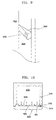
- Refrigerated air supply path will be explained hereinafter with reference to the Figs. 3-5.
- a portion of refrigerated air generated by an evaporator 108 in refrigerating chamber 111 is directed to the freezer compartment 110 and the other is directed to the fresh food compartment 120 through the passageway 130 by a fan unit 104.
- Refrigerated air guided to the passageway 130 is then divided into two by the connecting duct 132.
- a portioned of the divided refrigerated air is provided into a fresh food duct 124 mounted at the rear of the fresh food compartment 120, while the other is provided into the connecting duct 132.
- Refrigerated air in the fresh food duct 124 is spouted into the fresh food compartment 120 forward through a plurality of outlets 126 formed on the front surface thereof as indicated by arrows in Fig. 3.
- refrigerated air in the connecting duct 132 flows forward to the outlet 133 thereof and then, flows into the door duct 160, inlet 161 of which is communicated with the outlet 133 in door-closed state.
- the refrigerated air flows downward along with the vertical portion 162 and is distributed to the horizontal portions 164. Then, refrigerated air is spouted into the fresh food compartment 120 rearward through outlet openings 166.
- Refrigerated air provided into the fresh food compartment 120 carries out heat exchanges with the foodstuffs stored therein, then being relatively warmed air.
- the warmed air is returned to the evaporating chamber 111 where evaporator 108 is mounted through a return duct(not shown) and then being refrigerated air repeatedly by heat exchange with the evaporator 108.
- the connecting duct 132 is diverged from the passageway 130 in the insulation barrier 134.
- the barrier is a partition defined by an inner wall 103b of freezer compartment 110 and an inner wall 103a of fresh food compartment 120 in which insulation material, such as urethane is filled.
- insulation material such as urethane
- a connecting duct 232 is mounted in the interior of an insulation barrier 234 and a side wall 228 which is defined by an inner side wall 227 of a fresh food compartment 220 and an outer case 229.
- the connecting duct 232 is diverged from a passageway 230 which is a duct or a path for delivering refrigerated air to an fresh food duct 224 in the insulation barrier 234. Connecting duct 232 is then extended forward through the interior of the barrier 234 and the side wall 228 and have an outlet 233 formed on the front side surface of the side wall 228.
- the connecting duct 232 is extended forward through interior of the side wall 228 to the front side surface thereof. Substantially the side wall 228 defined by inner side wall 227 of fresh food compartment 220 and out case 229 is filled with insulation material as known. Also in this embodiment, the connecting duct 232 do not occupy any storage space in fresh food compartment 220 by mounting it in the interior of the side wall 228.
- a door duct 260 is mounted in the door 250.
- the inlet 261 formed on a side wall of the door 250 is communicated with the outlet 233 of the connecting duct 232 when door closed.
- the door duct 260 is provided with a vertical portion 262 and a pair of horizontal portions 264 with a plurality of outlet openings 266.
- the function of the door duct 260 is the same one as described above except that it is provided with an inlet 261 in the side surface thereof.
- Refrigerated air generated by an evaporator 208 is distributed either to fresh food duct 224 and door duct 260 through the passageway 230 and connecting duct 232. Similarly, refrigerated air is spouted into the fresh food compartment 220 forward through a number of outlets 226 of the fresh food duct 224 and rearward through a number of outlet openings 266 of door duct 260 respectively. Interior of the fresh food compartment 220 is, therefore, charged with new refrigerated air uniformly.
- connecting duct 232 of the embodiment is mounted in the side wall 228 and barrier 234 in insulated state without occupying any storage space in fresh food compartment 220.
- This embodiment disclose a connecting structure where refrigerated air in connecting duct will be delivered to door duct without leakage.
- a connecting member 340 is mounted on the inclined front surface 329 of fresh food compartment 320.
- an outlet 333 of connecting duct 332 is formed in the connecting member 340.
- a door duct 360 which has the same function and structure as explained above is mounted in the door 350.
- the door duct 360 is provided with an inlet 361 which is formed on the side surface of the door 350 to communicate with the outlet 333 of the connecting duct 332 when door closed.
- the connecting member 340 is protruded laterally toward the door 350 and is formed with resilient material to have close contact with the door 350 when closed.
- the connecting member 340 may be formed integrally with the inclined front surface 329 of the refrigerator.
- the connecting member 340 having outlet 333 of connecting duct 332 provides close contact with the side surface of the door 350 where inlet 361 of door duct 360 is formed.
- the refrigerated air which flows in the connecting duct 332 will be delivered to the door duct 360 without air leakage.
- connecting member 340 can provide close contact between connecting duct 332 and door duct 360 to prevent air leakage. Therefore, various modifications can be occurred in its contour and design.
- a connecting duct 432 is mounted along an inner side wall 428 of fresh food compartment 420.
- the connecting duct 432 is diverged from a passageway 430 in an insulation barrier 434 which is a duct or a path for guiding refrigerated air to a fresh food compartment 424.
- the inner side wall 402 is provided with a groove 460 as shown in Fig. 12 in which the connecting duct 432 is inserted.
- the groove 460 extends forward along the inner side wall 402.
- the connecting duct 432 is mounted in the groove 460 not to protrude inward in the fresh food compartment 420.
- the connecting duct 432 mounted in the groove 460 is surrounded by an insulation layer 464 which is cased by cover 462.
- connecting duct 432 is provided with its outlet 433 at the front surface of the side wall 428 which is communicated with an inlet of door duct(not shown) which is described and illustrated above.
- the connecting duct 432 is laid in the side wall 428 of the fresh food compartment 420 with surrounding insulation 464.
- an inner wall 402, an outer case 404 and an insulation 406 will be prepared as conventional except that the inner side wall 402 is provided with the groove 460. Therefore, the structure of the connecting duct 432 in this embodiment is easily applied to the conventional refrigerator.
- the connecting 432 duct having U section or pipe type section is assembled to the groove 460 of inner wall 403. Then assembling process will be finished by assembling insulation 464 and cover 462 on the connecting duct 432.
- connecting duct 432 also does not occupy any storage space in the fresh food compartment 420. And conventional problem occurred by temperature difference between connecting duct 432 and fresh food compartment 420 will be overcome, since the connecting duct 432 is cover with insulation 464. And as stated above, this embodiment may be easily applied to the conventional refrigerators, since it does not require any further structural change except the inner side wall 402.
- the refrigerator is divided into a freezer compartment 510 and a fresh food compartment 520 by an insulation barrier 534.
- a fresh food duct 524 is mounted vertically at the rear wall of fresh food compartment 520 and provided with a plurality of outlet openings 526 to spout refrigerated air into the fresh food compartment 520.
- a refrigerating chamber 511 is provided at the rear of the freezer compartment 510 where an evaporator 508 and a fan unit 504 is mounted.
- Refrigerated air generated by the evaporator 508 is provided into the fresh food duct 524 through a passageway 530 mounted in the barrier 534.
- the passageway 530 is communicated with a duct or space 515 defined by a shroud 506 and a grill 507.
- a connecting duct 532 of this embodiment is diverged at the uppermost portion of a fresh food duct 524 and mounted against the lower wall 534a of barrier 534.
- the connecting duct 532 extends forward along with the lower wall 534a and has an outlet 533 located in front of the fresh food compartment 520.
- a door duct 560 is mounted in the door 550 which closes the fresh food compartment 520.
- An inlet 561 of the door duct 560 is formed in the upper portion of the door 550 which communicates with the outlet 533 of connecting duct 532 when door closed, as shown in Fig. 14.
- Door duct 560 has an vertical portion 562 which is communicated with the inlet 561 and a pair of horizontal portions 564 which is communicated with the vertical portion 562.
- a plurality of outlet openings 566 are formed on the front surface of the horizontal portions 564. Refrigerated air flown into the door duct 560 through the connecting duct 532 is spouted into fresh food compartment 520 by the outlet openings 566, thereby cooling the door adjacent portion sufficiently in fresh food compartment 520.
- the outlet openings 566 of the door duct 560 is formed in a manner that refrigerated air spouted from the openings 566 passes through the food stored in the door baskets 552 respectively.
- the horizontal portions 564 may be formed integrally with the door baskets 552. And horizontal portions 564 may be mounted in the interior of the door baskets 552.
- the space occupied by the connecting duct 532 is not usually utilized as storage space, since the connecting duct 532 is diverged from at the upper most portion of the fresh food duct 524 and mounted along with the lower wall 534a of barrier 534.
- the connecting duct 532 is diverged from at the upper most portion of the fresh food duct 524 and mounted along with the lower wall 534a of barrier 534.
- food are stored on the shelves mounted horizontally in fresh food compartment 520 so that the space occupied by connecting duct 532 is not so much available for food storage.
- the connecting duct 532 may be formed integrally with either fresh food duct 524 or lower wall 534a of the barrier. In that case, assembling process for connecting duct 532 will be very simple, thereby reducing additive process.
- a damper device 680 is installed at a point in which a connecting duct 632 is diverged from a passageway 630.
- the passageway 630 is a duct or path for guiding refrigerated air to the fresh food compartment 620 through a path or duct 640 and a fresh food duct 624.
- the connecting duct 632 is a duct for delivering a portion of refrigerated air to the door duct described above.
- the damper device 680 controls amount of air flow to connecting duct 632 and to the path 640 respectively.
- damper device 680 Detailed description on internal structure of the damper device 680 is omitted herein, since the damper device 680 is known and there are various known damper devices which control amount of air flow in ducts.
- Refrigerated air generated by the evaporator(not shown) is guided into the passageway 630, and then flows into the path 640 and connecting duct 632 respectively.
- the damper device 680 is mounted in the passageway 630 where it is divided into path 640 and connecting duct 632, thereby controlling the amount of flow of refrigerated air respectively.
- the damper device 680 is provided with a pair of baffle 682, 684 which open and close the path 640 and connecting duct 632.
- the damper device 680 illustrated schematically is what so called “twin damper" having a pair of baffles.
- the baffle 682 controls the amount of refrigerated air which flows into the fresh food compartment 620 through the path 640 and fresh food duct 624. And the baffle 684 controls the amount of refrigerated air which flows into the door duct through the connecting duct 632.
- each damper device can be mounted in either in passageway 640 and connecting duct 632 respectively.
- the damper device 680 is controlled by a micro processor(not shown) which is mounted in the refrigerator. Control of the baffle 684 in the damper device 680 which controls the amount of air flow of connecting duct 632 is carried out on the basis of a temperature sensed by a sensor 694 which is mounted in door adjacent portion. And control of the baffle 682 in the damper device 680 which controls the amount of air flow of passageway 640 is carried out on the basis of a temperature sensed by a sensor 692 mounted in the fresh food compartment 620. For example, when the temperature sensed by the sensor 694 is high than desired, the micro processor controls the baffle 684 of the damper device 680 to be opened, thereby providing refrigerated air in the door adjacent portion. In case that a pair of separate damper devices is mounted in connecting duct 632 and passageway 640 respectively, the same control for the damper devices will be carried on the basis of the temperatures respectively sensed by the sensors 692, 694.
- refrigerated air is provided into the fresh food compartment by the fresh food duct and door duct respectively. This means that refrigerated air is spouted in the fresh food compartment forward and rearward simultaneously and this improves effective uniform cooling of the fresh food compartment.
- the connecting duct which delivers refrigerated air to the door duct is mounted in the interior of insulation barrier or in the interior of the side wall of fresh food compartment. This provides sufficient storage space in the fresh food compartment by the fact that the connecting duct does not occupy any space in the food storage space, that is fresh food compartment. And when connecting duct is mounted along with the lower wall of the barrier, the storage space is not so much limited than before, since the space occupied by the connecting duct is not so much utilized as storage space.
- connecting duct Conventional problems such as dewing and freezing on the outer surface of connecting duct can be overcome by mounting it in the interior of barrier or in the interior of side wall or at least mounting insulation layer on the connecting duct.
- Substantially the door adjacent portion is tent to be easily warmed, due to the inflow of warm air when door opened.
- the apparatus of this invention provides refrigerated air concentratedly in the door adjacent portion by the door duct when door closed, thereby cooling the portion promptly. Accordingly, food stored in a door adjacent portion in the fresh food compartment will be kept fresh in spite of frequent opening of the door.
- the food stored in the door basket which contacts relative warm air when door opened can be kept fresher by forming the outlet openings of the door duct in a position that refrigerated air spouted therefrom passes across the food stored in the door basket.
Priority Applications (1)
| Application Number | Priority Date | Filing Date | Title |
|---|---|---|---|
| EP03007769A EP1323993B1 (fr) | 1997-05-28 | 1998-05-11 | Réfrigérateur |
Applications Claiming Priority (14)
| Application Number | Priority Date | Filing Date | Title |
|---|---|---|---|
| KR9712222U | 1997-05-28 | ||
| KR9721270 | 1997-05-28 | ||
| KR9721269 | 1997-05-28 | ||
| KR1019970021269A KR19980085241A (ko) | 1997-05-28 | 1997-05-28 | 냉장고의 냉기공급구조 |
| KR1019970021270A KR19980085242A (ko) | 1997-05-28 | 1997-05-28 | 냉장고의 냉기공급구조 |
| KR2019970012222U KR200155506Y1 (ko) | 1997-05-28 | 1997-05-28 | 냉장고의 냉기공급구조 |
| KR9721668 | 1997-05-29 | ||
| KR1019970021668A KR19980085557A (ko) | 1997-05-29 | 1997-05-29 | 냉장고의 냉기공급구조 |
| KR1019970023845A KR19990000765A (ko) | 1997-06-10 | 1997-06-10 | 냉장고의 냉장실 냉기공급구조 |
| KR9723845 | 1997-06-10 | ||
| KR1019970023846A KR100220394B1 (ko) | 1997-06-10 | 1997-06-10 | 냉장고의 냉장실 냉기공급 구조 |
| KR9723846 | 1997-06-10 | ||
| KR9730575 | 1997-07-02 | ||
| KR1019970030575A KR100235439B1 (ko) | 1997-07-02 | 1997-07-02 | 냉장고의 냉기공급구조 |
Related Child Applications (1)
| Application Number | Title | Priority Date | Filing Date |
|---|---|---|---|
| EP03007769.7 Division-Into | 2003-04-04 |
Publications (3)
| Publication Number | Publication Date |
|---|---|
| EP0881441A2 true EP0881441A2 (fr) | 1998-12-02 |
| EP0881441A3 EP0881441A3 (fr) | 2000-05-10 |
| EP0881441B1 EP0881441B1 (fr) | 2004-09-29 |
Family
ID=36643430
Family Applications (2)
| Application Number | Title | Priority Date | Filing Date |
|---|---|---|---|
| EP98108545A Expired - Lifetime EP0881441B1 (fr) | 1997-05-28 | 1998-05-11 | Dispositif d'alimentation en air réfrigéré pour réfrigérateur |
| EP03007769A Expired - Lifetime EP1323993B1 (fr) | 1997-05-28 | 1998-05-11 | Réfrigérateur |
Family Applications After (1)
| Application Number | Title | Priority Date | Filing Date |
|---|---|---|---|
| EP03007769A Expired - Lifetime EP1323993B1 (fr) | 1997-05-28 | 1998-05-11 | Réfrigérateur |
Country Status (5)
| Country | Link |
|---|---|
| US (1) | US5979174A (fr) |
| EP (2) | EP0881441B1 (fr) |
| JP (1) | JP3391701B2 (fr) |
| CN (1) | CN1138955C (fr) |
| DE (2) | DE69826562T2 (fr) |
Cited By (8)
| Publication number | Priority date | Publication date | Assignee | Title |
|---|---|---|---|---|
| WO2003021168A1 (fr) * | 2001-09-04 | 2003-03-13 | BSH Bosch und Siemens Hausgeräte GmbH | Appareil de refrigeration a circulation d'air de refroidissement |
| WO2005003658A2 (fr) | 2003-07-04 | 2005-01-13 | Electrolux Home Products Corporation N.V. | Systeme pour la refrigeration d'un compartiment |
| EP1559972A2 (fr) * | 2004-01-28 | 2005-08-03 | Lg Electronics Inc. | Réfrigérateur |
| EP1559974A2 (fr) * | 2004-01-28 | 2005-08-03 | Lg Electronics Inc. | Passage d'air froid dans un réfrigérateur |
| WO2006120079A1 (fr) | 2005-05-10 | 2006-11-16 | BSH Bosch und Siemens Hausgeräte GmbH | Appareil frigorifique |
| WO2008146999A1 (fr) | 2007-05-25 | 2008-12-04 | Lg Electronics Inc. | Réfrigérateur |
| WO2012062845A2 (fr) | 2010-11-11 | 2012-05-18 | Arcelik Anonim Sirketi | Réfrigérateur dont la circulation d'air est régulée |
| EP2165131A4 (fr) * | 2007-05-25 | 2015-06-24 | Lg Electronics Inc | Réfrigérateur |
Families Citing this family (40)
| Publication number | Priority date | Publication date | Assignee | Title |
|---|---|---|---|---|
| KR100389382B1 (ko) * | 1998-11-28 | 2003-10-04 | 주식회사 엘지이아이 | 냉장고 |
| US6463752B2 (en) | 1999-02-26 | 2002-10-15 | Maytag Corporation | Refrigerator food storage compartment with quick chill feature |
| US6612116B2 (en) | 1999-02-26 | 2003-09-02 | Maytag Corporation | Thermoelectric temperature controlled refrigerator food storage compartment |
| US6343477B1 (en) * | 1999-02-26 | 2002-02-05 | Maytag Corporation | Refrigerator food storage temperature control system |
| SG106619A1 (en) * | 2000-07-21 | 2004-10-29 | Fujitsu General Ltd | Electric refrigerator |
| CA2355155C (fr) * | 2000-08-16 | 2009-10-13 | Lg Electronics Inc. | Appareil de refroidissement de porte pour un refrigerateur ayant une porte va-et-vient |
| DE10155369B4 (de) | 2000-11-22 | 2010-06-24 | Lg Electronics Inc. | Gerät für die Kaltluftpassage eines Kühlschranks |
| KR100451345B1 (ko) * | 2001-11-20 | 2004-10-06 | 주식회사 엘지이아이 | 냉장고의 냉기 공급장치 |
| KR100451354B1 (ko) * | 2001-11-23 | 2004-10-06 | 주식회사 엘지이아이 | 냉장고의 냉기 공급장치 |
| KR20030042757A (ko) * | 2001-11-23 | 2003-06-02 | 주식회사 엘지이아이 | 냉장고의 냉기 공급장치 |
| KR100453237B1 (ko) * | 2001-12-22 | 2004-10-15 | 삼성전자주식회사 | 냉장고 |
| KR100492575B1 (ko) * | 2002-08-17 | 2005-06-03 | 엘지전자 주식회사 | 좁은 수광각을 갖는 써모파일 적외선 센서 |
| KR100884952B1 (ko) * | 2002-12-06 | 2009-02-23 | 엘지전자 주식회사 | 냉장고의 냉기 공급장치 |
| KR100884953B1 (ko) * | 2002-12-06 | 2009-02-23 | 엘지전자 주식회사 | 냉장고의 냉기 공급장치 |
| US6865905B2 (en) * | 2003-03-11 | 2005-03-15 | General Electric Company | Refrigerator methods and apparatus |
| TR200704187T1 (tr) * | 2004-12-22 | 2007-08-21 | Arçeli̇k Anoni̇m Şi̇rketi̇ | Bir soğutucu. |
| CN100575831C (zh) * | 2005-01-06 | 2009-12-30 | Lg电子株式会社 | 用于冰箱的门管道组件 |
| DE102008054934A1 (de) * | 2008-12-18 | 2010-07-01 | BSH Bosch und Siemens Hausgeräte GmbH | Kältegerät sowie Verfahren zur Temperaturregelung in einem Kältegerät |
| CN101893361B (zh) | 2009-05-22 | 2016-01-20 | 博西华家用电器有限公司 | 冰箱 |
| TWI437196B (zh) * | 2010-06-21 | 2014-05-11 | Toshiba Kk | 冰箱 |
| CN103047810A (zh) * | 2012-12-30 | 2013-04-17 | 合肥华凌股份有限公司 | 冰箱 |
| US9733008B2 (en) * | 2013-03-13 | 2017-08-15 | Whirlpool Corporation | Air flow design for controlling temperature in a refrigerator compartment |
| US9562707B2 (en) | 2013-03-14 | 2017-02-07 | Whirlpool Corporation | Refrigerator cooling system having a secondary cooling loop |
| JP2015152276A (ja) * | 2014-02-18 | 2015-08-24 | 株式会社東芝 | 冷蔵庫 |
| US10890370B2 (en) * | 2014-12-31 | 2021-01-12 | Bsh Hausgeraete Gmbh | Cooling device having an air channel and a baffle |
| CN107131700B (zh) * | 2016-02-26 | 2019-11-29 | 合肥美的电冰箱有限公司 | 冰箱 |
| KR101835336B1 (ko) * | 2016-03-09 | 2018-03-07 | 엘지전자 주식회사 | 냉장고 |
| US10087569B2 (en) | 2016-08-10 | 2018-10-02 | Whirlpool Corporation | Maintenance free dryer having multiple self-cleaning lint filters |
| US10738411B2 (en) | 2016-10-14 | 2020-08-11 | Whirlpool Corporation | Filterless air-handling system for a heat pump laundry appliance |
| US10519591B2 (en) | 2016-10-14 | 2019-12-31 | Whirlpool Corporation | Combination washing/drying laundry appliance having a heat pump system with reversible condensing and evaporating heat exchangers |
| CN106802048A (zh) * | 2016-12-09 | 2017-06-06 | 青岛海尔股份有限公司 | 冰箱 |
| US10502478B2 (en) | 2016-12-20 | 2019-12-10 | Whirlpool Corporation | Heat rejection system for a condenser of a refrigerant loop within an appliance |
| US10514194B2 (en) | 2017-06-01 | 2019-12-24 | Whirlpool Corporation | Multi-evaporator appliance having a multi-directional valve for delivering refrigerant to the evaporators |
| KR102320766B1 (ko) * | 2017-06-02 | 2021-11-03 | 엘지전자 주식회사 | 냉장고 |
| EP3438579A1 (fr) | 2017-07-31 | 2019-02-06 | Whirlpool Corporation | Refroidissement augmenté de compartiment de port au moyen d'un conduit d'air dans une configuration de réfrigération à double évaporateur |
| US10718082B2 (en) | 2017-08-11 | 2020-07-21 | Whirlpool Corporation | Acoustic heat exchanger treatment for a laundry appliance having a heat pump system |
| US10520239B2 (en) * | 2018-01-24 | 2019-12-31 | Haier Us Appliance Solutions, Inc. | Refrigerator appliance and air duct therefor |
| KR102365546B1 (ko) | 2018-04-20 | 2022-02-21 | 엘지전자 주식회사 | 냉장고 |
| KR102521634B1 (ko) * | 2018-06-04 | 2023-04-14 | 엘지전자 주식회사 | 냉장고 |
| US11000133B2 (en) * | 2019-09-27 | 2021-05-11 | Pepsico, Inc. | Vacuum-insulated cooler |
Citations (1)
| Publication number | Priority date | Publication date | Assignee | Title |
|---|---|---|---|---|
| US5584191A (en) | 1994-01-10 | 1996-12-17 | Goldstar Co., Ltd. | Cool air supply apparatus of refrigerator |
Family Cites Families (12)
| Publication number | Priority date | Publication date | Assignee | Title |
|---|---|---|---|---|
| US3283528A (en) * | 1965-02-12 | 1966-11-08 | Amana Refrigeration Inc | Air distribution system for combination freezer-refrigerator |
| US4009589A (en) * | 1976-01-02 | 1977-03-01 | General Electric Company | Single evaporator, single fan combination refrigerator with independent temperature controls and method of adjustment |
| JPH0748033B2 (ja) * | 1989-09-12 | 1995-05-24 | 三菱電機株式会社 | 冷凍冷蔵庫 |
| US5359860A (en) * | 1991-04-16 | 1994-11-01 | Goldstar Co. Ltd. | Method and apparatus for controlling a temperature in a refrigerating chamber of a refrigerator |
| CA2079977A1 (fr) * | 1991-10-10 | 1993-04-11 | Brent A. Ledet | Systemes a roue d'entrainement pour le calage de lames de metal espacees sur la largeur de bandes transporteuses en plastique |
| KR970011047B1 (ko) * | 1992-02-21 | 1997-07-05 | 삼성전자 주식회사 | 냉장고의 냉각장치 |
| KR100203983B1 (ko) * | 1995-04-06 | 1999-06-15 | 전주범 | 냉장고 |
| KR0162412B1 (ko) * | 1995-10-13 | 1999-02-18 | 구자홍 | 냉장고의 신규 부하 집중 냉각장치 |
| KR970024861U (ko) * | 1995-11-30 | 1997-06-20 | 냉장고 댐퍼커버의 취부구조 | |
| JP3184775B2 (ja) * | 1997-02-20 | 2001-07-09 | 大宇電子株式會▲社▼ | エアカーテン生成装置を利用したドアからの冷気吐出機能を有する冷蔵庫 |
| US5927095A (en) * | 1997-05-20 | 1999-07-27 | Lg Electronics, Inc. | Anti-frost device for refrigerators |
| JP4018238B2 (ja) * | 1997-05-27 | 2007-12-05 | エルジー エレクトロニクス インコーポレイティド | 冷蔵庫の冷気供給システム |
-
1998
- 1998-05-11 EP EP98108545A patent/EP0881441B1/fr not_active Expired - Lifetime
- 1998-05-11 EP EP03007769A patent/EP1323993B1/fr not_active Expired - Lifetime
- 1998-05-11 DE DE69826562T patent/DE69826562T2/de not_active Expired - Fee Related
- 1998-05-11 DE DE69832212T patent/DE69832212T2/de not_active Expired - Fee Related
- 1998-05-26 CN CNB981019846A patent/CN1138955C/zh not_active Expired - Fee Related
- 1998-05-28 JP JP14778898A patent/JP3391701B2/ja not_active Expired - Fee Related
- 1998-05-28 US US09/085,007 patent/US5979174A/en not_active Expired - Lifetime
Patent Citations (1)
| Publication number | Priority date | Publication date | Assignee | Title |
|---|---|---|---|---|
| US5584191A (en) | 1994-01-10 | 1996-12-17 | Goldstar Co., Ltd. | Cool air supply apparatus of refrigerator |
Cited By (16)
| Publication number | Priority date | Publication date | Assignee | Title |
|---|---|---|---|---|
| US7093453B2 (en) | 2001-09-04 | 2006-08-22 | Bsh Bosch Und Siemens Hausgeraete Gmbh | Refrigerator with cold air circulation |
| WO2003021168A1 (fr) * | 2001-09-04 | 2003-03-13 | BSH Bosch und Siemens Hausgeräte GmbH | Appareil de refrigeration a circulation d'air de refroidissement |
| CN101943509B (zh) * | 2003-07-04 | 2012-07-04 | 伊莱克斯家用产品股份有限公司 | 柜式冷藏系统 |
| EP2282147A1 (fr) | 2003-07-04 | 2011-02-09 | Electrolux Home Products Corporation N.V. | Congélateur bahut |
| US9157674B2 (en) | 2003-07-04 | 2015-10-13 | Electrolux Home Products Corporation N.V. | Cabinet refrigerating system |
| WO2005003658A3 (fr) * | 2003-07-04 | 2005-05-19 | Electrolux Home Prod Corp | Systeme pour la refrigeration d'un compartiment |
| WO2005003658A2 (fr) | 2003-07-04 | 2005-01-13 | Electrolux Home Products Corporation N.V. | Systeme pour la refrigeration d'un compartiment |
| EP1559974A3 (fr) * | 2004-01-28 | 2011-05-11 | LG Electronics, Inc. | Passage d'air froid dans un réfrigérateur |
| EP1559972A2 (fr) * | 2004-01-28 | 2005-08-03 | Lg Electronics Inc. | Réfrigérateur |
| EP1559972A3 (fr) * | 2004-01-28 | 2011-05-18 | LG Electronics, Inc. | Réfrigérateur |
| EP1559974A2 (fr) * | 2004-01-28 | 2005-08-03 | Lg Electronics Inc. | Passage d'air froid dans un réfrigérateur |
| WO2006120079A1 (fr) | 2005-05-10 | 2006-11-16 | BSH Bosch und Siemens Hausgeräte GmbH | Appareil frigorifique |
| WO2008146999A1 (fr) | 2007-05-25 | 2008-12-04 | Lg Electronics Inc. | Réfrigérateur |
| EP2165130A4 (fr) * | 2007-05-25 | 2015-06-10 | Lg Electronics Inc | Réfrigérateur |
| EP2165131A4 (fr) * | 2007-05-25 | 2015-06-24 | Lg Electronics Inc | Réfrigérateur |
| WO2012062845A2 (fr) | 2010-11-11 | 2012-05-18 | Arcelik Anonim Sirketi | Réfrigérateur dont la circulation d'air est régulée |
Also Published As
| Publication number | Publication date |
|---|---|
| DE69826562T2 (de) | 2006-02-16 |
| EP0881441A3 (fr) | 2000-05-10 |
| EP1323993A3 (fr) | 2003-07-16 |
| EP1323993A2 (fr) | 2003-07-02 |
| DE69832212T2 (de) | 2006-07-20 |
| EP1323993B1 (fr) | 2005-11-02 |
| CN1138955C (zh) | 2004-02-18 |
| JPH1151537A (ja) | 1999-02-26 |
| DE69832212D1 (de) | 2005-12-08 |
| JP3391701B2 (ja) | 2003-03-31 |
| CN1200471A (zh) | 1998-12-02 |
| US5979174A (en) | 1999-11-09 |
| EP0881441B1 (fr) | 2004-09-29 |
| DE69826562D1 (de) | 2004-11-04 |
Similar Documents
| Publication | Publication Date | Title |
|---|---|---|
| EP1323993B1 (fr) | Réfrigérateur | |
| US5392615A (en) | Air conduit system in a refrigerator | |
| US5546759A (en) | Refrigerator having a vegetable compartment and a separate kimchi chamber | |
| KR102627719B1 (ko) | 냉장고 | |
| US6062037A (en) | Refrigerated air supply apparatus for refrigerator | |
| JPS6246126Y2 (fr) | ||
| JP2001147072A (ja) | 電気冷蔵庫 | |
| AU744612B2 (en) | Refrigerated air supply apparatus for refrigerator | |
| JP3439981B2 (ja) | 冷蔵庫 | |
| JPS62288468A (ja) | 5温度式冷蔵庫 | |
| JP2575915B2 (ja) | 冷蔵庫 | |
| JP3599946B2 (ja) | 冷蔵庫 | |
| JP3172314B2 (ja) | 冷蔵庫 | |
| MXPA98004225A (en) | Refrigerated air supply apparatus for refrigeration | |
| KR100438938B1 (ko) | 냉장고의 냉기순환구조 | |
| JPH0336477A (ja) | 冷凍冷蔵庫 | |
| JPH09138050A (ja) | 冷蔵庫 | |
| KR100451344B1 (ko) | 사이드 바이 사이드형 냉장고의 급속냉동장치 | |
| JPH0718944Y2 (ja) | 冷蔵庫の通風装置 | |
| KR20230116577A (ko) | 냉장고용 그릴팬 어셈블리 및 냉장고 | |
| JPH0113984Y2 (fr) | ||
| JPH0442695Y2 (fr) | ||
| JPH0769107B2 (ja) | 冷凍冷蔵庫 | |
| KR19990001505A (ko) | 냉장고의 냉기순환구조 | |
| JPH01300180A (ja) | 冷蔵庫 |
Legal Events
| Date | Code | Title | Description |
|---|---|---|---|
| PUAI | Public reference made under article 153(3) epc to a published international application that has entered the european phase |
Free format text: ORIGINAL CODE: 0009012 |
|
| AK | Designated contracting states |
Kind code of ref document: A2 Designated state(s): DE GB IT |
|
| AX | Request for extension of the european patent |
Free format text: AL;LT;LV;MK;RO;SI |
|
| PUAL | Search report despatched |
Free format text: ORIGINAL CODE: 0009013 |
|
| AK | Designated contracting states |
Kind code of ref document: A3 Designated state(s): AT BE CH DE DK ES FI FR GB GR IE IT LI LU MC NL PT SE |
|
| AX | Request for extension of the european patent |
Free format text: AL;LT;LV;MK;RO;SI |
|
| 17P | Request for examination filed |
Effective date: 20001110 |
|
| AKX | Designation fees paid |
Free format text: DE GB IT |
|
| 17Q | First examination report despatched |
Effective date: 20021203 |
|
| GRAP | Despatch of communication of intention to grant a patent |
Free format text: ORIGINAL CODE: EPIDOSNIGR1 |
|
| GRAS | Grant fee paid |
Free format text: ORIGINAL CODE: EPIDOSNIGR3 |
|
| GRAA | (expected) grant |
Free format text: ORIGINAL CODE: 0009210 |
|
| RIN1 | Information on inventor provided before grant (corrected) |
Inventor name: SHIN, SUNG HO Inventor name: BAE, GYOO JONG Inventor name: YOON, KYUNG SEOK Inventor name: PARK, SANG HO Inventor name: KIM, SEOK RO |
|
| AK | Designated contracting states |
Kind code of ref document: B1 Designated state(s): DE GB IT |
|
| REG | Reference to a national code |
Ref country code: GB Ref legal event code: FG4D |
|
| REF | Corresponds to: |
Ref document number: 69826562 Country of ref document: DE Date of ref document: 20041104 Kind code of ref document: P |
|
| PLBE | No opposition filed within time limit |
Free format text: ORIGINAL CODE: 0009261 |
|
| STAA | Information on the status of an ep patent application or granted ep patent |
Free format text: STATUS: NO OPPOSITION FILED WITHIN TIME LIMIT |
|
| 26N | No opposition filed |
Effective date: 20050630 |
|
| PGFP | Annual fee paid to national office [announced via postgrant information from national office to epo] |
Ref country code: IT Payment date: 20090522 Year of fee payment: 12 Ref country code: DE Payment date: 20090511 Year of fee payment: 12 |
|
| PGFP | Annual fee paid to national office [announced via postgrant information from national office to epo] |
Ref country code: GB Payment date: 20090506 Year of fee payment: 12 |
|
| GBPC | Gb: european patent ceased through non-payment of renewal fee |
Effective date: 20100511 |
|
| PG25 | Lapsed in a contracting state [announced via postgrant information from national office to epo] |
Ref country code: IT Free format text: LAPSE BECAUSE OF NON-PAYMENT OF DUE FEES Effective date: 20100511 |
|
| PG25 | Lapsed in a contracting state [announced via postgrant information from national office to epo] |
Ref country code: DE Free format text: LAPSE BECAUSE OF NON-PAYMENT OF DUE FEES Effective date: 20101201 |
|
| PG25 | Lapsed in a contracting state [announced via postgrant information from national office to epo] |
Ref country code: GB Free format text: LAPSE BECAUSE OF NON-PAYMENT OF DUE FEES Effective date: 20100511 |