EP0880933A1 - Machine pour le traitement de sols - Google Patents
Machine pour le traitement de sols Download PDFInfo
- Publication number
- EP0880933A1 EP0880933A1 EP98107324A EP98107324A EP0880933A1 EP 0880933 A1 EP0880933 A1 EP 0880933A1 EP 98107324 A EP98107324 A EP 98107324A EP 98107324 A EP98107324 A EP 98107324A EP 0880933 A1 EP0880933 A1 EP 0880933A1
- Authority
- EP
- European Patent Office
- Prior art keywords
- care
- floor
- disc
- discs
- support
- Prior art date
- Legal status (The legal status is an assumption and is not a legal conclusion. Google has not performed a legal analysis and makes no representation as to the accuracy of the status listed.)
- Granted
Links
Images


Classifications
-
- A—HUMAN NECESSITIES
- A47—FURNITURE; DOMESTIC ARTICLES OR APPLIANCES; COFFEE MILLS; SPICE MILLS; SUCTION CLEANERS IN GENERAL
- A47L—DOMESTIC WASHING OR CLEANING; SUCTION CLEANERS IN GENERAL
- A47L11/00—Machines for cleaning floors, carpets, furniture, walls, or wall coverings
- A47L11/40—Parts or details of machines not provided for in groups A47L11/02 - A47L11/38, or not restricted to one of these groups, e.g. handles, arrangements of switches, skirts, buffers, levers
-
- A—HUMAN NECESSITIES
- A47—FURNITURE; DOMESTIC ARTICLES OR APPLIANCES; COFFEE MILLS; SPICE MILLS; SUCTION CLEANERS IN GENERAL
- A47L—DOMESTIC WASHING OR CLEANING; SUCTION CLEANERS IN GENERAL
- A47L11/00—Machines for cleaning floors, carpets, furniture, walls, or wall coverings
- A47L11/02—Floor surfacing or polishing machines
- A47L11/10—Floor surfacing or polishing machines motor-driven
- A47L11/14—Floor surfacing or polishing machines motor-driven with rotating tools
- A47L11/16—Floor surfacing or polishing machines motor-driven with rotating tools the tools being disc brushes
- A47L11/164—Parts or details of the brushing tools
-
- A—HUMAN NECESSITIES
- A47—FURNITURE; DOMESTIC ARTICLES OR APPLIANCES; COFFEE MILLS; SPICE MILLS; SUCTION CLEANERS IN GENERAL
- A47L—DOMESTIC WASHING OR CLEANING; SUCTION CLEANERS IN GENERAL
- A47L11/00—Machines for cleaning floors, carpets, furniture, walls, or wall coverings
- A47L11/40—Parts or details of machines not provided for in groups A47L11/02 - A47L11/38, or not restricted to one of these groups, e.g. handles, arrangements of switches, skirts, buffers, levers
- A47L11/4036—Parts or details of the surface treating tools
- A47L11/4038—Disk shaped surface treating tools
-
- A—HUMAN NECESSITIES
- A47—FURNITURE; DOMESTIC ARTICLES OR APPLIANCES; COFFEE MILLS; SPICE MILLS; SUCTION CLEANERS IN GENERAL
- A47L—DOMESTIC WASHING OR CLEANING; SUCTION CLEANERS IN GENERAL
- A47L11/00—Machines for cleaning floors, carpets, furniture, walls, or wall coverings
- A47L11/40—Parts or details of machines not provided for in groups A47L11/02 - A47L11/38, or not restricted to one of these groups, e.g. handles, arrangements of switches, skirts, buffers, levers
- A47L11/4052—Movement of the tools or the like perpendicular to the cleaning surface
- A47L11/4058—Movement of the tools or the like perpendicular to the cleaning surface for adjusting the height of the tool
-
- A—HUMAN NECESSITIES
- A47—FURNITURE; DOMESTIC ARTICLES OR APPLIANCES; COFFEE MILLS; SPICE MILLS; SUCTION CLEANERS IN GENERAL
- A47L—DOMESTIC WASHING OR CLEANING; SUCTION CLEANERS IN GENERAL
- A47L11/00—Machines for cleaning floors, carpets, furniture, walls, or wall coverings
- A47L11/40—Parts or details of machines not provided for in groups A47L11/02 - A47L11/38, or not restricted to one of these groups, e.g. handles, arrangements of switches, skirts, buffers, levers
- A47L11/4063—Driving means; Transmission means therefor
- A47L11/4069—Driving or transmission means for the cleaning tools
Definitions
- the invention relates to a floor care device, in particular Floor polisher, with at least one rotating drivable Care disc and possibly a peripheral suction device.
- Such a floor care device in the form of a floor polisher is known from DE-OS 43 40 367.
- Each individual carrier certificate will be designed accordingly Care insert in the form of a polishing disc in the way of a Clip connection assigned, which clip connection is reversible.
- the drive of the care discs load-bearing carrier disks is carried out on a rubber-like ring running surfaces of the carrier disks acting Motor pinion.
- Nursing documents are also known which has Velcro fasteners on carrier discs be attached. This proves the exchange the care coverings as very time consuming and unsanitary, because when the coverings are removed, the user comes into contact with the dirty surfaces.
- device-side Clip tongues in one, based on the thickness of the care pane, central mounting for driving the care disc intervention.
- the care disc or the bearing axis selected to be longer in length than half the thickness of the washer including the topping.
- the care disc an essentially centrally trained one Support molding for support in the floor care device has, this support formation against a Care surface is sunk.
- Floor care devices with several care discs, e.g. three care discs there is a possibility that each individual washer driven by a drive shaft becomes. According to the invention, however, it is provided that just a washer over a drive shaft is driven and this, for example.
- the care disc serves both as a support the washer on a drive shaft as well a centering shaft for the not directly driven Care discs.
- a floor care device with several care discs given the opportunity to do this because of their equal Exchange design with each other.
- the arrangement of the care discs the floor care device takes place contrary to the known State of the art not by means of locking or the like, but here it is rather the case that the Care discs on both sides, e.g.
- a hemispherical have axially arranged support formation, in which the respective, correspondingly shaped end face Wave enters.
- the floor care device is based on this on the care discs, making the latter alone at least securely held in its radial direction are. Due to the fact that no connecting elements or the like must be opened, for example easy changing of the care discs or turning them given.
- the centrally trained according to the invention Support molding can also be used on care discs with one-sided Care surface to be used, with the support molding on the opposite of the care surface Side of the care disc is formed. The drive the care disc or when using several care discs the one washer is loosened, that associated with the support formation opposite Abutment for a drive shaft of the floor care device are formed.
- a centering or insertion recess is formed in front of the support formation on the device side. So is in the area of the washer hub, which is the support formation and has the opposite abutments a spherical or conical contour to form the Centering or insertion recess provided so that even with a large axis offset of the drive shaft or centering shaft and washer hub find it yourself or self-centering is guaranteed. This happens even with non-parallel axes.
- the subject of the invention is provided that the abutment is free-standing in the circumferential direction is.
- training can be selected in which the abutment is web-like, radially outwards molded onto the hub from the support shape is.
- a Care disc has a circumferential toothing.
- a powered washer the other care discs via their teeth drives. This training can on the drive side on an additional transfer case to be dispensed with. An immediate one is preferred Drive of the other care discs by the powered maintenance disc.
- one or more care discs indirectly with interposition a directly driven care disc to drive.
- Circumferential rotary bearing is designed for rotatable reception the care disc in a possibly from the floor care device separate bracket.
- This rotary pivot bearing can, for example, in the form of a support formation and possibly encompassing the abutment, circular in cross section Hollow cylinder formed with radial collar at the end be.
- the design of the star-shaped Bracket is preferably chosen so that Circumferential rotary brackets according to the arrangement of Drive and centering shafts are positioned.
- Care discs can give an asymmetry be, with which the assignment of a specially molded Drive maintenance disc is specified.
- the user can not be driven Care disc with a non-drivable Mix up the care disc.
- the circumferential rotary bracket is circular in cross section is formed with a through opening, into which the circumferential pivot bearing of a care disc is recorded.
- the circumferential rotary bracket have an annular groove on the inside, in which a correspondingly shaped annular bead of the peripheral pivot bearing the care disc enters.
- the bracket is a central positive connection for fastening in the floor care device having.
- This positive connection can, for example, in the form a plug connection. So that is Users by simply attaching the care discs carrying bracket an easy arrangement of the Care discs made possible. Through appropriate floor cutouts of the device, the user can insert or Insertion aid for correct alignment of the bracket be given. Further through such training also a self-finding of the positive connection to Attachment of the bracket given in the floor care device be.
- the bracket as Exchange cassette is formed in which several Care discs are held around the edges.
- a care disc in the removable cassette is supported with vertical play.
- This In a preferred training game is about that 0.25 to 0.5 times the thickness of the carrier disc, i.e. of the Thickness of the washer minus the thickness of the topping.
- a care disc held in the removable cassette with horizontal play is. The measure of this horizontal play is For example, about 0.5 to 1 times the thickness of the carrier disk.
- each care disc is enclosed at the edge.
- the exchange of the cassette is preferred around an axis of symmetry, for example by the position of Force transmission points through meshing or friction surface, is determined.
- the reversible cassette also encompasses here only the edge area of the care discs. Of the The area of the care coverings remains free to create a bilateral Ensure usage. When used on one side the removable cassette is preferred on the side opposite to the care coverings except for the secondary area of the individual care discs closed for coupling the same to the device educated.
- the bracket applies that the bracket by positive locking to the floor care device is coupled, the connection to the drive unit will be produced. This leaves the care discs receiving holder, in particular the exchangeable cassette weightless. The support of the device weight takes place via the hubs of the Care discs.
- bracket has design or construction features, that make it easier to insert the bracket and to rule out incorrect operation.
- a solution corresponding color markings or Positive locking elements on floor care device and bracket represent which with a corresponding counter marking must be brought into line.
- care discs has also proven to be advantageous with an essentially centrally trained one Support molding for support in the floor care device of the type already described.
- the care discs through the holder for example through the exchangeable cassette prepositioned so that it is around a defined Sliding game, but not interchangeable are, with the hubs through one of the Support molding upstream of the centering or Insertion recess automatically assigned Find the drive or centering shaft.
- the care discs are captive interconnected and at the same time changing or reversible.
- the franking in the device housing significantly larger than the outside diameter of the work surface especially bristled care discs, whereby the pane edge areas are still largely covered will.
- wall mounting etc.
- special protection against incorrect operation is advantageous, i.e. illegal disc combinations, e.g. two bean slices combined with a polishing disc.
- the direction of rotation of the care discs is always further equal.
- the bristles show through creep effects long operation a permanent deformation - tangential Inclination - on.
- the mounting solution e.g. in The shape of a reversible cassette prevents incorrect insertion of the discs.
- Another combination is different Slice sizes possible. It is also conceivable that by printing and / or color design of the Bracket visualizes the different functions can be.
- the cassette solution allows nevertheless the greatest possible coverage of the edge of the care disc, because a one-time assembly in the Production of bristled care discs for smaller ones Postage in the cassette is possible.
- the cassette closes the larger franking on the device.
- toothed Care discs associated with a higher level of operator protection.
- the toothing in front of hurled stones etc. protected with which this is not in the gearing can wedge.
- Using toothed Care discs are always in the holder a fixed orientation to each other about the axis of rotation arranged. This enables the use of asymmetrical Care coverings, e.g. Egyptian covering forms, with what a reduction in the raw edge strip can be achieved.
- the invention further relates to a floor care device type in question, the floor care device a Has drive shaft, for driving a care disc, with a drive coupling that with a support and Drive shape of the washer interacts.
- Coupling systems for transmission are known in the device sector a torque from a drive unit Care discs that drive or frictionally or positively Connect care discs together.
- a form-fitting Drive is from the beginning in the state of the Technology mentioned German published application. Usually these connections are rigid, by means of screw connection or quick release different Design type. Systems with swiveling are less common or axially movable care discs for the purpose Compensation for unevenness on machined surfaces.
- the clutch has a support finger for Transmission of a vertical force and a drive finger for transmitting a torque, the Drive finger relative to the support finger essentially is vertically resilient.
- the configuration according to the invention the drive clutch is here for both itself as well as in combination with the one described above Design of the care disc and / or with the design a holder for the care discs, such as an exchangeable cassette of importance.
- the clutch-side support finger enters a corresponding one Forming, for example.
- the essentially central trained support formation of the care disc Which support finger the floor care device is on that supports the washer. This will a vertical force is passed under the care disc at the same time securing the same in the radial direction.
- Centering or insertion recess is also in one larger axis misalignment of the support finger and care disc hub a self-finding or self-centering guaranteed.
- An embodiment is preferred in which the support finger is hemispherical on the head side is with a corresponding pan-like design hub-side support formation.
- Such a trained one Support fingers are preferred both in the area a drive shaft and not in the area of one driven centering shaft or the like use.
- This configuration provides a clutch which is an oblique, angular and offset Joining of input and output allowed, whereby retrofitting is further simplified.
- the Care discs to be arranged are essentially only through that, through the support fingers on the disks device weight essentially in the radial direction secured, with a configuration of the care discs with one driving the other care discs External gearing thereby further stability given is.
- the drive finger By essentially vertical elasticity of the drive finger is a swiveling and a male sliding the driven maintenance disc to compensate for Unevenness in the processing of surfaces, being this swiveling and male displaceability even with the non-powered, just by given a support finger centered washer discs is.
- the support finger acts with an abutment Care disc together, the abutment, as already mentioned, preferably in the form of a radially oriented of the support-shaped web is trained. This is where the invention turns out vertical resilience of the drive finger as an advantage. Collide when joining from the drive or output side those used to transmit the circumferential force Positive locking elements, as tight as the drive finger against the spring force axially.
- the drive finger and the support finger are made in one piece, being between the drive finger and the support finger a spring arm is formed. So it can be provided that the drive finger and the support finger as one one-piece plastic molded part are formed, the drive finger on a radially projecting Spring arm of the support finger is arranged. Will continue suggested that two opposing drive fingers are trained.
- the drive finger on a from the support finger separate component in the form of a Driver plate is formed. Next is here provided that the driver plate via a spiral spring is supported on the drive shaft. This coil spring allows the vertical resilience of the Driver plate shaped drive finger relative to the support finger.
- the driver plate in the circumferential direction positive, but vertically movable on the Support finger is fixed.
- the drive shaft of the drive clutch and also, as is further preferred, a centering shaft or the like, a support finger with an integrally formed, spherical Surface on, with the drive shaft continuing Has positive locking elements for torque transmission.
- a driver plate is provided, which with the support finger positively connected in the circumferential direction is. The driver plate is relative to Support fingers axially displaceable and pivotable around the Axes perpendicular to the drive axis. The positive locking elements of support fingers and drive plates are in permanent engagement.
- the takeaway plate has additional positive locking elements, which for Transfer a peripheral force, according to the invention in the form of one or two drive fingers.
- the spring element in the form of a spiral spring presses as long no external forces act on the system, one Driving plate-side stop edge against an assigned Edge of the support finger. While in the last embodiment described three separate components (Support finger, drive finger and spring element in the form a coil spring) are present in the first-mentioned embodiment in one component, e.g. integrated as a molded plastic part. It is essential that support finger, drive finger and axially acting Spring element are torsionally rigidly connected.
- the Spring element acts axially and tangentially.
- the Systems will experience an abrupt increase in torque in the clutch avoided by deforming the spring element until the support finger and the drive finger in turn form a torsionally rigid connection.
- the invention further relates to a floor care device type in question with a care disc and one, drive shaft arranged in an upper housing part for the care disc.
- the care discs are replaced from the underside of the device forth. This results in handling disadvantages since the device is switched to the rear with every change must be rotated. Any further contaminate Bristle strips and the base plate area.
- the task is to design a floor assembly in such a way that a simple, quick care disc change is possible, with the bottom group in is the easiest to clean. First of all and essentially only in the radial direction secured, vertical but free plug connection between the washer and the drive shaft, and a removable bottom plate, which in closed condition the care disc in vertical Secures direction, solved.
- the bottom plate is hinged hinged.
- the care disc by overlapping the edge in the Base plate secured against falling down is. Accordingly, the bottom cutout of the bottom plate according to the diameter of the care coverings, preferred chosen slightly larger, the care disc as such compared to the care surface diameter larger is trained.
- a toothing can be made in this edge area be provided, which by the edge overlap in the base plate is placed in a hidden position. This overlap forms the securing of the care disc in one vertical direction. In the other The care disc is locked in the vertical direction Condition due to the inserted drive shaft or Centering shaft secured. It is also proposed that the maintenance disc is only operational on the upper housing part is supported vertically and is mounted radially.
- the base plate can be folded down on the upper housing part attached and, for example with a locking mechanism, lockable or unlockable. In operation supports the upper part of the housing settles on the care discs, the latter not touching the base plate. This means that the base plate only in operation protection of the internal components against contamination forms.
- a hook abutment in the upper part of the housing for movement into an unlocked position is pivotally mounted.
- This Hook abutment is in a preferred embodiment in the form of a cylinder with a circular cross section designed to grip the engagement hook in the Locking position.
- the engagement hook of the base part unlocks.
- the hook abutment in its locked position is spring biased. It can also be provided that the hook abutment in its unlocked position is biased. In the latter case, the spring serves as Lift mechanism, which is relocated when actuated the hook abutment in the unlocked position is discharged.
- the latter can a displacement of the hook abutment in the closed position, depending on the version also in the open position be effected.
- the hook abutment on one, in the top of the Housing upper part arranged and for projecting over the extendable actuating lever acts on the upper side.
- the hook abutment can lever translated on the underside of the operating lever support, with the hook abutment in the course of the opening movement of the actuating lever in a Top of the projecting position shifted.
- the operating lever in the open position can be operated, for example by means of foot pressure.
- This also provides a visual display of the open position given.
- the hook abutment lever translated with a, in the top of the upper housing part arranged operating lever connected is.
- the latter can be in the form of a foot-operated, stored in a recess of the upper housing part and with the top of the housing part in the locked position aligned aligned button trained be, further a rocker switch or a rocker button is preferred.
- the hook abutment pivotably formed a locking part is that to solve the locking by means of Actuating lever can be actuated.
- the locking part of the energy storage in the on Hook abutment spring By swiveling the locking part of the energy storage in the on Hook abutment spring released, after which the entire locking mechanism in an unlocked position panned.
- the locking part for interaction with the operating lever with an actuating cam protruding upwards is provided.
- An unlocking element acts on this, which on the actuating lever in the form of a release finger or the like can be molded.
- the unlocking member is in the form of a pusher, which both integrated in the operating lever as well as a separate component locally separated from the operating lever arranged in the top of the upper housing part is.
- the hook abutment at the end of an abutment lever is arranged with its other end hook abutment and acts on the actuating lever
- Actuating levers here preferably form separate ones Components that are each rotatably supported.
- a stop-limited rotational displacement of the abutment lever with the limit stop positioned so that the lever arm acting on the operating lever in a dead center position or in an over dead center position is held. In this position the Actuating lever can not be operated, because also at Pressure on the actuating lever of the abutment lever or the lever arm acting on the operating lever is locked remains.
- the another lever arm with a lower housing side Collision slope cooperates to overcome the dead center position of a lever arm during a closing process.
- An embodiment is preferred here which the hook abutment in the course of the closing process along a bevel on the lower part of the housing runs what a rotational movement of the abutment lever effected from the dead center position.
- the locking mechanism includes a grip element forming an actuating lever, which fits positively in the device contour.
- the abutment lever By pressing the Handle element, the abutment lever is operated, whereby the upper part of the housing against the preload by the measure the distance position raised and by means of the pawl is locked against the upper housing part.
- the Actuators can be in different ways combined or designed as separate components.
- the configuration according to the invention makes it easier Handling due to low actuation forces and an easier application of the housing flap given because this is only prepositioned.
- Essential is that a form-fitting in the device housing fitted grip element accessible at the push of a button is, the accessibility of the handle element by a spring or locking force without permanent external influence preserved. It is just prepositioning the parts of the device to be connected - here the upper part of the housing and base plate - required. The induction the end position of the device parts does not occur Moving one or both parts of the device, but by means of Actuation of a separate, possibly spatial remote control. The operating forces and travel are independent of the locking element or from the pawl. This means in particular that the pawl forming the locking element in locked state mechanically by the control elements can be decoupled, which is a self-locking Locking and high resilience as a result enables short power flow paths.
- the hook abutment lever translated with a, in the top of the upper housing part arranged actuator interacts.
- one in the top arranged slider of the upper housing part be which the hook abutment in a the lower housing part releasing position relocated.
- the hook abutment for Solution from the engagement hook is linearly displaceable.
- a linear displaceability is preferred here against the force of a preload spring. It is also envisaged that the hook abutment to release from the engagement hook following the linear displacement one Rotary movement is carried out while releasing the pre-tensioning spring.
- the hook abutment has a run-on rounding for turning back the hook abutment in the closed position a case closing process. This reverse rotation of the Finally, the hook abutment has a linear backward displacement the hook abutment in the locked position Episode. It proves to be particularly advantageous here that a locking lug on the axis of the hook abutment is designed to generate a turnstile, which in the course of the linear movement to cancel the Turnstile can be pulled out of a lock receptacle.
- the invention further relates to a plurality of care discs for a floor care device, in particular floor polisher, if necessary with a peripheral suction device.
- a plurality of care discs as Exchange set is included in a holder.
- a plurality of maintenance disks are operational not detachably accommodated in the holder are.
- the brackets is star-shaped.
- an advantageous Training is provided that on the bracket each assigned to a central area of a care disc a circumferential rotary bracket is formed. It is also proposed that the circumferential rotary bracket positively connected to a circumferential pivot bearing of the care disc is.
- the Circumferential rotary bracket in cross section circular is formed with a through opening into which the circumferential pivot bearing of a washer was added is.
- the bracket is a central one Form-locking connection position for fastening in the floor care device.
- the bracket is designed as a removable cassette is in which several care disks surround the edge are supported.
- a Care disc in the removable cassette with vertical Game is held.
- a care disc in the removable cassette with horizontal Game is held.
- each disc is enclosed.
- the removable cassette the floor care device is positively locked.
- the removable cassette training two, essentially Uniformly shaped outer sides on both sides in the floor care device is sustainable.
- the invention further relates to a care disc for a floor care device, in particular floor polisher, if necessary with a peripheral suction device.
- a care disc for a floor care device in particular floor polisher, if necessary with a peripheral suction device.
- the care disc for use on both sides is provided with a care covering on both sides and can be fastened on both sides in the floor care device.
- the care disc be set aside an essentially centrally formed support formation for support in the floor care device, this support formation against a care surface is sunk.
- assigned to the support form opposite abutments for a drive shaft of the floor care device are formed.
- upstream in the axial direction on the device side the support formation has a centering or insertion recess is trained.
- Abutment designed free-standing in the circumferential direction is.
- that between the abutments essentially in Passage openings running circumferentially are.
- the care disc opposite, different Care coverings are applied.
- a washer has a circumferential toothing having.
- a driven Care disc over their teeth the others Care discs drives.
- coaxial to the support formation on the Care disc is a circumferential rotary bearing designed for rotatable mounting of the care disc in a, if necessary by the floor care device separate bracket.
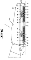
- a floor care device 1 in the form of a floor polisher, which three, a device base 2 essentially penetrating care discs 3.
- the equipment floor 2 has a cutout 4, the contour of which given by the arrangement of the care discs 3 is.
- the floor care device 1 is on the floor side with a peripheral End strip 5 provided.
- a peripheral suction device be provided for the collection of coarse and fine dust.
- This care disc 3 is for use on both sides on both sides 6 and 7 provided a care surface, the same on both sides Care coverings can be arranged.
- embodiment is a preferred arrangement chosen with two opposite, different Care coverings 8 and 9.
- the care disc 3 has a circular plan, plate-like base support 10 at its edge a circumferential toothing 11 is formed. Is in the middle the base support 10 is provided with a hub 12.
- This hub 12 extends on both sides of the base support 10 in the axial direction to the same extent, being in the Hub 12 one side 6 or 7 of the care disc 3 assigned a centrally formed support formation 13 is formed. This is opposite a hub face 14 arranged sunk, further the hub end face 14 compared to the respective surface of the care surface is arranged axially recessed, with a Offset dimension, which is about half the base carrier thickness corresponds.
- a centering or Insertion recess 15 upstream coaxially is based on the hub end face 14 in front of each support formation a centering or Insertion recess 15 upstream coaxially.
- Both the Support formation 13 as well as the centering or insertion recess 15 are approximately hemispherical, the centering or insertion recess 15 an enlarged compared to the radius of the support formation 13 Has diameter.
- a ratio of centering or Insertion recess radius for support formation radius selected from about 2: 1.
- the care disc 3 has abutments on both sides 16 for a drive shaft of the floor care device 1. These are on both sides of the base support 10 in the form of Radial blades formed. These, the abutments 16 forming wings are molded on the outside of the Nahe 12, with two being preferred, as shown diametrically opposed abutments 16 per side Form 6 or 7 of the care disc 3.
- Each abutment 16 extends in the axial direction from Basic carrier 10, which is thinner in the hub area is as in the outer area that supports the covering, to the level of the hub end face 14.
- each abutment 16 On the back surface facing away from the loading side each abutment 16 is provided with support ribs 17 (see Fig. 3).
- care discs 3 are shown, which with opposite, different Care coverings 8 and 9 are provided.
- the chosen one Design of the care discs can also be used same coverings can be used on both sides.
- An essential feature of the care disc according to the invention 3 is that this is not taken into account the possibly different care coverings around a perpendicular to the axis of rotation and in the center of the Base support 10 extending axis x mirror symmetry is trained.
- This configuration is the Care disc 3 can be used on both sides, whereby for changing the covering type or the covering surface only the care disc 3 is turned through 180 ° must become.
- a reversible care disc is, however also conceivable for training in which the edge surface of the base support 10, for example with a rubber tread or the like is formed.
- the mentioned circumferential toothing 11 serves for the drive of the other care discs 3.
- the in Fig. 1 with the reference number 3 care disc is about a drive shaft of the floor care device 1 driven.
- the two other care discs 3 ' are over with the peripheral teeth 11 of the main drive pulley 3 driven directly.
- a care disc 3 ' is active is driven, the care disc 3 immediately above this and the other care disc 3 'indirectly via the care disc 3 is driven.
- an interchangeable care disc is 3 specified. This can often shared flooring types, e.g. to polishing and Polishing or cleaning and soft cleaning in just one Care disc 3 can be integrated.
- the disc turns 180 ° around the axis x appropriate covering type for use.
- Symmetrical to Disc level x is a bilateral in the care disc 3
- Coupling system integrated with the care disc 3 can be coupled to a drive shaft, with how later described in more detail that device weight as Disc normal force is initiated.
- the Care disc 3 has easily recognizable gripping areas on. In a configuration of a care disc 3 with the same covering on both sides is a longer, for example doubled Given the useful life of the care discs 3.
- the exchangeable cassette 20 is essentially designed as a hollow profile body, with lining passage openings 21, which both on the Cassette top 22 as well as on the opposite Page 23 are trained.
- the exchangeable cassette 20 essentially has one contour adapted to the outer contour of the care discs in the ground plan three circular, one into the other Areas.
- the edge of each Care disc 3 areas are in one Cross-section formed in a C-shape, with the edge wrap the provided here on the care discs 3 Circumferential teeth 11 are covered.
- the care discs 3 are in the interchangeable cassette 20 a vertical game, which game size approximately half the thickness of the base support 10 washer 3 corresponds.
- the exchangeable cassette 20 is on the floor care device 1 positively locked, for example by means of a clip holder or similar.
- an underside of the cassette is aligned - in the figures shown, page 23 - with the level of the device base 2 (cf. FIG. 5).
- care discs 3 used, as already with reference to FIGS. 1 to 3 have been described.
- the support finger 24 is with the drive shaft of the floor care device 1 connected and has drive fingers 26, which against the abutment 16 of the washer 3 for driving kick them.
- the care discs 3 are due to the selected design captive and pre-positioned in the removable cassette 20 arranged.
- the exchangeable cassette 20 is planar about this axis of symmetry y mirror image molded.
- the one for the passage of the removable cassette 20 recess 27 formed in the base 2 of the device the removable cassette 20 is designed according to the floor plan.
- the exchangeable cassette is around the specified axis of symmetry y 20 together with the care discs held therein 3 reversible, provided reversible maintenance discs 3 with respect to 1 to 3 described type can be used.
- FIG. 6 shows an exchangeable cassette 28 for Use of a covering 9 provided only on one side Care discs 29.
- the covering 9 opposite cassette top side - in FIG. 6 the page 22 - closed up to the hub area.
- the holder 19 is in one shown another embodiment.
- the Bracket 19 designed as a star-shaped support frame 30, which is a central positive connection 31, of which three radially outward Support arms 32 extend.
- the support arms have ends 32 circular rotary rotary mounts in plan 33.
- the care discs held by the support frame 30 34 are provided on one side with a care covering 9 and point on the opposite of the care surface 9 Page one that has already been described with reference to FIGS. 1 to 3 Design of the care discs, same Design with respect to the support formation 13 and Centering or insertion recess 15. Are further abutment 16 is also provided here.
- Coaxial to yours Support formation 13 is on each care disc 34 Circumferential rotary bearing 35 designed for rotatable reception the washer 34 in the circumferential rotary holder 33 of the Support frame 30.
- the arrangement is chosen so that the peripheral pivot bearing 35 an annular shoulder 36 in the area of its free end trains.
- the peripheral rotating bracket 33 of the support frame 30 has a central through opening 37 in which - viewed in the direction of insertion - one at the end, the through hole diameter enlarging and the Ring shoulder 36 of the circumferential rotary bearing 35 adapted Ring groove 37 is formed.
- the care disks 34 are already, for example, in the factory pre-assembled on the support frame 30, the orientation the support arms 32 of the support frame 30 accordingly the positioning of the care discs 34 in the floor care device 1 are aligned.
- the support frame used in the floor care device 1 30 is form-fitting via the form-fitting connection point 31 supported.
- the case bottom has an approximately the same Outer contour of the three care discs 34 corresponding Contour on. This corresponds to the exemplary embodiments shown about the contour shown in Fig. 1 the recess 4. This configuration is therefore the Bracket 19 even with a floor care device 1, as it is is shown in Fig. 1 with originally individually mounting washers 3 can be used.
- bracket 19 the respective Disc support by positive locking to the floor unit 1 coupled, the connection to the drive unit will be produced.
- the bracket 19 remains Device weight not applied. The support of the device weight takes place via the hubs 12 of the respective care discs 3, 29 and 34, respectively.
- the bracket 19 has design or construction Features that clearly insert the removable cassette 20 or 28 or the support frame 30 facilitate and rule out incorrect operation. You can do this For example, corresponding color markings, such as. 4 are shown (reference numeral 38). This can also be done by positive locking elements on Floor care devices 1 or the device floor 2 and the respective bracket 19 to be solved. Such corresponding Form-locking elements, which according to the Overall training mirror-symmetrical or on the axis of symmetry y are arranged, for example, in FIG. 4 with provided with the reference number 39. 8 is in the correct position Arrangement of the support frame 30 on the Axis of symmetry y extending towards the center Web 40 provided, which is in the wrong orientation of the support frame 30 of care window areas is applied to prevent the onset.
- the care discs are pre-positioned by the bracket 19, so that they can be moved around a defined game, but are not interchangeable.
- the Care discs are still captive with each other connected and at the same time manipulable in the form of a Changing or turning the same.
- toothed washers these are in the holder 19 always in a fixed orientation arranged around the axis of rotation to each other. This makes possible the use of asymmetrical disc coverings, such as e.g. Egyptian topping forms, with a reduction of the unprocessed edge strip can be achieved.
- 11 to 13 is in an exemplary embodiment a dome system for the care discs 3, 29 or 34 shown.
- a dome system for the care discs 3, 29 or 34 shown In these figures only the function and coupling of a reversible Care disc 3 described. The designs are however also transferable to the care discs 29 and 34.
- a drive shaft 41 is shown with a support finger connected non-rotatably to this end 42.
- the support finger 42 is hemispherical at the end formed, with the support finger 42 Vertical force from the floor care device 1 via the support formation 13 of the Nahe 12 introduced into the care disc 3 becomes.
- Support finger 42 has four at the same angle to each other arranged, radially projecting driving cams 43. in the The area of its lower edge is between the driving cams 43 outer wall of the supporting finger, one ring shoulder each 44 shaped.
- the support finger 42 thus formed also serves in the not directly driven washers 3 for centering the same, these support fingers 42 on not driven centering shafts are arranged.
- a driver plate 45 is also provided, which has a central opening 46 for passage of the support finger 42, of which opening 46 four aligned at the same angle to one another, radially outwardly extending slots 47, which after joining support finger 42 and drive plate 45 a positive connection by entry of the driving cams 43 form between these parts.
- the driver plate 45 is supported on the underside Ring shoulder 44 of the support finger 42.
- the driver plate 45 has two on the underside diametrically opposite drive fingers 48, for Formation of the form-fitting entrainment of the care disc 3 in the area of their abutments 16.
- the driver plate 45 is supported by a spiral spring 49 on the drive shaft 41.
- This configuration means that the driver plate 45 is in Circumferential direction, but vertically movable fixed to the support finger 42.
- the driver plate 45 is relative to the support finger 42 axially displaceable and pivotable around the perpendicular to the Drive axis z standing axes.
- the positive locking elements of support finger 42 and driving plate 45 yourself in permanent engagement.
- the drive plate 45 has additional positive locking elements which for Serve to transfer a peripheral force.
- FIG. An alternative embodiment is shown in FIG.
- these components are now integrated, for example as Plastic molded part.
- Support fingers 24 and 42, drive fingers 26 or 48 and the axially acting spring element are torsionally rigid with one another connected.
- support fingers and drive fingers can be used opposite to the drive torque by means of the spring element be resiliently clamped in the circumferential direction.
- the drive fingers 26 and 48 give way against the spring force axially.
- the orientation of the drive finger changes 26 or 48 and hub with respect to the drive axle, whereby the drive finger due to the spring force axially its starting position relative to the support finger resumes. This creates a dead angle again a positive connection between the input and output side.
- the Nahe 12 shows the care disc 3 positive locking elements, which are used to transmit a Serve circumferential force on the drive finger 26.
- a pan-like thrust bearing (support formation 13) forms the opposite contour to the drive-side support finger.
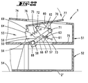
- 15 to 18 is another embodiment of the floor care device 1, in which one Upper housing part 51 of device 1 has a base plate 52 is assigned pivotable.
- the base plate 52 can be folded down on the upper housing part 51 attached and with a locking mechanism 53 locked or unlocked.
- the care discs 29 are positioned, for which the base plate 52 covering passage openings 21, the Dimensions are chosen so that the care discs 29 at least partially overlapped in the bottom plate 52 are secured against falling out.
- care disks are preferred in the 1 to 3 shown and described for this purpose used. However, it is only shown Care disks provided with a covering on one side 29.
- the essentially box-shaped base plate 52 forms the Device floor 2 ', which is not affected by the Care discs 3 is touched. Rather, it turns out here between an underside 7 of the care discs 29 and the device base 2 'a gap s.
- the support fingers 24 and 25 secure the care discs 29 in operation in both vertical and radial Direction.
- the device base 2 'of the base plate 52 serves during the operation of the floor care device 1 only to cover the inside of the device.
- One application variant is the possibility that to set up the entire floor care device 1 and then unlock the bottom plate 52. The latter is then fold down.
- the care disks are located after this 29 free in the base plate 52 and can in easily changed or turned.
- the Cover passage openings 21 of the base plate 52 serve for prepositioning the changed or turned care discs 29 or 3.
- the bottom plate 52 and the upper housing part 51 after an unlocking are completely detachable from each other. This, for example, for cleaning the interior or for replacement the base plate 52.
- a snap connection or a locking mechanism effective at several points, which when unlocking the base plate 52 fully released.
- Locking mechanism 53 is an embodiment of the Locking mechanism 53 shown. This continues essentially from an engagement hook on the base plate side 55 and one in the upper housing part 51 arranged, disengageable abutment arrangement together.
- the engagement hook 55 is in the area of the device bottom 2 'rotatably connected to the base plate 52 and passes in the closed state of the floor care device 1 19 a slot 56 of the upper housing part 51 and plunge into the latter.
- the abutment arrangement on the upper part of the housing sets continues essentially from an abutment lever 57 with end-shaped, pin-like hook abutment 58, a pivotable about the hook abutment 58 Locking part 59 and a trained as a foot switch Operating lever 60 together.
- the abutment lever 57 is in the upper part of the housing 51 fixed lugs 61 rotatably mounted and has an approximately perpendicular to the longitudinal extension of the Abutment lever 57 and towards the operating lever 60 aligned bearing arm 62.
- Abutment spring 63 in the form of a cylindrical tension spring arranged, which the abutment lever 57 in a biases the lug 61 pointing pivoting direction.
- the locking part 59 pivotable about the hook abutment 58 is with one toward the operating lever 60 facing actuating cam 64 provided.
- actuating cam 64 and the bearing arm 62 of the abutment lever 57 is a cam bias spring 65, also positioned in the form of a cylindrical tension spring, for biasing the locking part 59 in a locking position.
- the blocking part forms on the underside of the hook abutment 58 59 a support bracket 68.
- the actuating lever 60 designed as a foot switch is rotatable on the bearing arm 62 of the actuating lever 60 stored.
- the associated with the locking part 59 of the Actuating lever 60 forms an inward on the Actuating cam 64 acting on contact finger 69, which in the embodiment shown as a cylindrical Body is formed.
- the rotatable mounting of the operating lever 60 on the Bearing arm 62 takes place somewhat off-center to the longitudinal extent of the operating lever 60, with which this seesaw-like is stored.
- the actuating lever 16 is supported by a web 70 on the pivot bearing 71 of the abutment lever 57.
- the Arrangement is chosen so that the web 70 on the side of the actuating lever axis of rotation facing away from the release finger 69 72 with the same distance to this is formed on the underside of the actuating lever 60.
- the bottom region 73 of the upper housing part 51 has a window for the passage of the abutment arrangement in the In the process of unlocking.
- the operating lever 60 is in an upper one Integrated housing wall 74 of the upper housing part 51.
- the hook abutment 58 underpins the abutment lever 57 of the base plate 52, the support bracket 68 of the Locking part 59 on the bottom 75 of the upper housing part 51 is supported in the region of an edge of the window 53.
- the base plate 52 is thereby securely on the upper housing part 51 supported.
- the operating lever 60 is in an opening 76 of the upper housing wall 74 in alignment with this one.
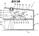
- the actuating lever 60 is briefly For example, by means of foot pressure, pivoted such that the molded release finger 69 the actuating cam 64 of the locking part 59 for rotational displacement of the same against the biasing force of the cam bias spring 65 disengages.
- the support bracket on the locking part side 68 from its position on the floor in Direction shifted to the window 73, for example simultaneous, slight rebound of the loaded Floor area.
- Such an intermediate position is in Fig. 20 shown.
- the cam bias spring acts 65 a provision of the locking part 59 in the starting position in which the cantilever arm 66 is supported on the abutment lever-side pin 67.
- the abutment spring 63 causes a pivoting complete abutment arrangement in the Unlocked position, being in the course of this rotational displacement around the pivot bearing 71 the cylindrical release finger 69, offset from the level to the locking part 59, on the top of the Engagement hook 55 presses. This will make the bottom plate 52 into a distance position to the upper housing part 51 pressed (see Fig. 21).
- the engagement hook 55 lies thereafter free, with which the upper housing part 51 - like Dotted lines in Fig. 21 - from the bottom plate 52 can be pivoted.
- a separate release finger 69 is provided. This is designed in the form of a spring-loaded button and does not swing as in the previously described Exemplary embodiment, in the course of unlocking with the Actuating lever 60 with. The latter is rotatable with the Abutment lever 57 connected. This is triggered here the mechanics by pressing the release finger 69, after which the abutment arrangement automatically due to the bias of the abutment spring 63 in the Unlocked position pivoted.
- the release finger can also be used, as in FIG. 25 shown in the form of a sliding element 78 be, which engages the actuating cam 64.
- the Sliding element 78 is integrated in the actuating lever 60 and in the simplest way by the operator relocatable. In the course of this relocation, the blocking part 59 shifted to the desired release position, after which the entire abutment arrangement in the open position panned.
- the locking mechanism according to the invention draws is characterized in that a form-fitting in the upper housing part 51 fitted handle as an operating lever 60 becomes accessible at the push of a button.
- This accessibility remains without permanent spring or locking force receive external influences.
- To bring about the end position of the two Device parts are not made by moving an or both parts of the device, but by pressing one separate, possibly spatially distant Control element (release finger 69 or sliding element 78).
- the actuation forces and travel ranges are independent from the locking element (here the locking part 59).
- 26 to 28 show another alternative Design of the locking mechanism 53.
- the abutment lever 57 not with the operating lever 60 connected, but acts on the underside this one.
- This abutment lever 57 is on both sides of the rotary bearing 71 arranged on the upper part of the housing formed, wherein a lever arm 80 has a release cam on the end 81 trains to support the same the bottom of the operating lever 60.
- the other Lever arm 82 carries hook abutment 58 at the end.
- This locking mechanism 53 is in accordance with the Embodiments described above, but here not shown, secured by means of a locking part.
- a locking part for example Pressing a release finger, the mechanics triggered.
- the abutment lever 57 then pivots spring-assisted in the release hook 55 Position according to FIG. 27.
- a torsion spring can be arranged, which with a spring leg on the abutment lever 57 acts.
- tension spring can be used.
- the operating lever 60 By triggering the locking mechanism and that associated pivoting of the abutment lever 57, the operating lever 60 is swung out, wherein the release cam 81 of the abutment lever 57 on the The underside of the operating lever moves along. Of the The operating lever 60 is then above the top of the upper housing part 51 for a closing operation.
- the upper housing part 51 continues from the Lowered housing part 52 pivoted, so the Abutment lever 57 automatically spring-assisted in a the actuating lever 60 locking position since the Abutment lever 57 is supported by the ramp 83 is missing (cf. Fig. 28).
- the swing-up movement of the abutment lever 57 is through a housing upper part Stop 84 limited, the latter is positioned so that it is stable End position of the lever arm 80 in a dead center or Dead center position. This has the consequence that the operating lever 60 in this housing open position is locked and therefore cannot be operated. It can not therefore the mechanics without a lock of the lower part of the housing can be operated.
- the operating lever 60 is also conceivable 60 to inhibit only when actuated.
- the stop 84 is to be positioned so that the Abutment lever 57 or its lever arm 80 in the open position of the housing is arranged before the dead center. As a result, the actuating force to shift the Operating lever 60 raised.
- FIGS. 28 to 34 Another alternative embodiment of the locking mechanism 53 is shown in FIGS. 28 to 34. Here are those in the previous embodiments separated components - abutment lever 57 and locking part 59 - united in a double locking lever 85. Out of this there is a reduction in parts.
- This double locking lever 85 has a hook abutment 58, which has a bottom, eccentric to the abutment axis of rotation has shaped run-out curve 86.
- an axis 87 is formed, which is a housing upper part Axle bearing 88 interspersed.
- the hook abutment 58 engages in the closed position according to the figures 29 to 32 the locking part 59 on the underside of the housing part.
- the lower housing part 52 is on the upper housing part 51 bound.
- a further Driver 89 attached, which for actuating the Locking mechanism 53 via a housing upper part Actuating element 90 can be acted upon.
- the latter is in the form of a slide in the area of the upper housing wall 74 trained.
- the driver 89 is on the hook abutment 58 facing away from the axle bearing 88.
- the axis 87 extending further over driver 89 carries one at the end, at an acute angle to the axial direction aligned boom 91. At this is continue, approximately at an angle of 45 ° to the plane extension of the boom 91 aligned boom arm 92 molded.
- bias spring 94 excited which the functions of the abutment spring 63rd and the cam bias spring 65 of those previously described Embodiments united.
- the arrangement of the bias spring 94 is made so that it is in a space diagonal extends, i.e. both at an angle to the Upper part of the housing as well as at an angle to the axis 87.
- a locking lug 95 is formed on the axis 87, which in the locked position of the locking mechanism 53 in a lock receptacle 96 in the area the axle bearing 88 rests (cf. in particular Fig. 30) this forms a turnstile, which the function of the locking part from the previous examples takes over.
- the depth of the hook abutment viewed in the axial direction 58 is dimensioned so that at least up to Lifting the turnstile this is always engaged with the engagement hook 55 of the lower housing part 52.
- the actuating element dragging the double locking lever 85 linearly 90 can be unlocked after actuation the locking mechanism 53, for example, spring-assisted return to its original position.
- the actuating element 90 it is also conceivable for the actuating element 90 to couple with the driver 89 of the double locking lever 85. As a result, the position is also outward the actuating element 90 the current position the locking mechanism recognizable.
- Subject of the invention is also a floor care device which is assigned to abutment 16 opposite support formation 13 molded for a drive shaft of the floor care device 1 are.
- Subject of the invention is also a floor care device in the axial direction on the device side upstream of the support formation 13 a centering or insertion recess 15 is formed is.
- Subject of the invention is also a floor care device in which the abutment 16 is free-standing in the circumferential direction.
- Subject of the invention is also a floor care device in which between the Abutments 16 extending substantially in the circumferential direction Passage openings 18 are formed.
- Subject of the invention is also a floor care device with which on the care disc 3 opposite, different care toppings 8, 9 are applied.
- Subject of the invention is also a floor care device with a care disc 3 has a circumferential toothing 11.
- Subject of the invention is also a floor care device where a powered Care disc 3 through their teeth 11 the others Care discs 3 'drives.
- Subject of the invention is also a floor care device in which a plurality of care discs 3, 29, 34 not operationally removable are accommodated in the holder 19.
- bracket 19 is star-shaped.
- Subject of the invention is also a floor care device with which on the bracket 19 each assigned to a central area Care disc 34 is formed a circumferential rotary bracket 33 is.
- Subject of the invention is also a floor care device in which the circumferential rotary bracket 33 with a circumferential rotary bearing 35 Care disc 34 is positively connected.
- Subject of the invention is also a floor care device in which the cross section is circular, with a Through opening in which the circumferential rotary bearing 35 a washer 34 is added.
- Subject of the invention is also a floor care device in which the bracket 19 a central positive connection 31 for Has attachment in the floor care device 1.
- Subject of the invention is also a floor care device with a care disc 3, 29 in the removable cassette 20, 28 with vertical Game is held.
- Subject of the invention is also a floor care device with a care disc 3, 29 in the removable cassette 20, 28 with horizontal Game is held.
- Subject of the invention is also a floor care device in which in the removable cassette 20, 28 each care disc 3, 29 enclosed at the edge is.
- Subject of the invention is also a floor care device in which the removable cassette 20, 28 on the floor care device 1 with positive locking is.
- Subject of the invention is also a floor care device in which in the removable cassette 20 forming two, essentially Uniformly shaped outer sides 22, 23 on both sides in the Floor care device 1 can be held.
- Subject of the invention is also a floor care device where the drive finger 26 and the support fingers 24, 25 are formed in one piece are, between the drive finger 26 and the Support fingers 24, 25, a spring arm 50 is formed.
- Subject of the invention is also a floor care device with two opposite Drive fingers 26 are formed.
- Subject of the invention is also a floor care device where the drive finger 48 on a separate from the support finger 42 Component in the form of a drive plate 45 is.
- Subject of the invention is also a floor care device with which the driver plate 45 via a spiral spring 49 on the drive shaft 41 is supported.
- Subject of the invention is also a floor care device with which the driver plate 45 form-fitting in the circumferential direction, however vertically movably fixed on the support finger 42 is.
- Subject of the invention is also a floor care device in which the floor care disc 3, 29, 34 by overlapping edges in the base plate 52 is secured against falling down.
- Subject of the invention is also a floor care device in which the floor care disc 3, 29, 34 operationally only on the upper housing part 51 is supported radially supported vertically.
- Subject of the invention is also a floor care device in which the floor part 52 on the upper housing part 51 by means of an engagement hook 55 is releasably supported.
- Subject of the invention is also a floor care device in which the engagement hook 55 from the top of the upper housing part 51 can be unlocked.
- Subject of the invention is also a floor care device with a hook abutment 58 in the upper housing part 51 for movement in an unlocked position pivotally mounted is.
- Subject of the invention is also a floor care device in which the hook abutment 58 spring biased into its locking position is.
- Subject of the invention is also a floor care device in which the hook abutment 58, spring-loaded in its unlocked position is.
- Subject of the invention is also a floor care device in which the hook abutment 58 lever translates to one, in the top of the upper housing part 51 arranged actuating lever 60 acts.
- Subject of the invention is also a floor care device in which the hook abutment 58 lever translates to one, in the top of the upper housing part 51 arranged and for projecting Actuating lever 60 extendable over the top acts.
- Subject of the invention is also a floor care device in which the hook abutment 58 lever translated with one in the top of the upper housing part 51 arranged actuating lever 60 is connected.
- Subject of the invention is also a floor care device with which on the hook abutment 58 formed a locking part 59 pivotable is that to solve the locking by means of Actuating lever 60 is actuated.
- Subject of the invention is also a floor care device in which the locking part 59 to interact with the operating lever 60 with an actuating cam 64 projecting upwards is.
- Subject of the invention is also a floor care device with which the actuation cam 64 or the locking part 59 in its locked position spring biased by a cam bias spring 65 is.
- Subject of the invention is also a floor care device in which the cam bias spring 65 is attached to the abutment lever 57.
- Subject of the invention is also a floor care device in which the hook abutment 58 arranged at the end of an abutment lever 57 is that with its other end on the operating lever 60 acts.
- Subject of the invention is also a floor care device in which the abutment lever 57 on both sides of an upper part of the housing attached pivot bearing 71 is formed.
- Subject of the invention is also a floor care device in which the operating lever 60 associated lever arm 80 in the housing open position arranged in a dead center position which is an operation of the operation lever 60 prevents.
- Subject of the invention is also a floor care device where the other Lever arm 82 with a bevel on the lower part of the housing 83 cooperates to overcome the dead center position of a lever arm 80 during a closing process.
- Subject of the invention is also a floor care device in which the abutment lever 57 fixed to the housing in an open position Hook abutment 58 is biased.
- Subject of the invention is also a floor care device in which a Opening movement of the actuating cam 64 via a Disengaging movement of the engagement hook 55 or the base plate 52 in a distance position to the upper housing part 51 is pressed.
- Subject of the invention is also a floor care device in which the hook abutment 58 lever translated with one in the top of the upper housing part 51 arranged actuating element 90 interacts.
- Subject of the invention is also a floor care device in which the hook abutment 58 to release from the engagement hook 55 linear is movable.
- Subject of the invention is also a floor care device in which the hook abutment 58 to release from the engagement hook 55 in Connection to the linear displacement a rotary movement performs with relaxation of the bias spring 94.
- Subject of the invention is also a floor care device in which the hook abutment 58 has a run-up curve 86 for the backward rotation of the hook abutment 58 in the closed position in a case closing process.
- Subject of the invention is also a floor care device with which on the axis 87 of the hook abutment 58 a locking lug 95 for generation a turnstile is formed, which in the course the linear movement to cancel the turnstile a lock receptacle 96 can be withdrawn.
- Subject of the invention is also a floor care device in which the locking device 96 on the upper part of the housing in the area of an axle bearing 88 of the hook abutment 58 is arranged.
- the invention also relates to a plurality of Care discs in which the holder 19 the majority of care discs as an exchange set and / or the majority of maintenance disks operationally are not detachably received in the holder and / or the holder is star-shaped and / or each assigned to a central area of a care disc 34 a circumferential rotary holder 33 is formed and / or the circumferential rotary holder 33 with a circumferential rotary bearing 35 of the care disc 34 positively connected and / or the circumferential rotary bracket 33 in cross section is circular, with a through opening, in which the circumferential pivot bearing 35 of a care disc 34 is received and / or the holder 19 a central positive connection point 31 for attachment in the floor care device 1 and / or as Exchangeable cassette 20, 28 is formed, in which several care discs 3, 29 held around the edges are and / or a care disc 3, 29 in the removable cassette 20, 28 is supported with vertical play and / or a care disc 3, 29 in the exchangeable cassette 20, 28 is supported with
- the invention also relates to a care disc in which the washer is essentially double-sided centrally formed support formation 13 opposite a care surface 8, 9 arranged sunk is and / or assigned to the support configuration 13 opposite Abutment 16 for an operating shaft of the Floor care device 1 are formed and / or in the axial direction on the device side upstream of the support formation 13 a centering or insertion recess 15 is formed and / or the abutment 16 is free-standing in the circumferential direction is formed and / or between the abutments 16 essentially extending in the circumferential direction Passage openings 18 are formed and / or on the care disc 3 opposite, different Care coverings 8, 9 are applied and / or a care discs 3 has a circumferential toothing 11 and / or a powered washer 3 on their teeth 11 drives the further care discs 3 'and / or coaxial to the support formation 13 on the care discs 34 a circumferential rotary bearing 35 is formed for rotatable Inclusion of the care disc 34 in one, possibly from
Priority Applications (1)
| Application Number | Priority Date | Filing Date | Title |
|---|---|---|---|
| EP03009824A EP1338235B9 (fr) | 1997-05-02 | 1998-04-22 | Pluralité de disques d'entretien de sols pour un appareil d'entretien de sols |
Applications Claiming Priority (4)
| Application Number | Priority Date | Filing Date | Title |
|---|---|---|---|
| DE19718496 | 1997-05-02 | ||
| DE19718496 | 1997-05-02 | ||
| DE19728927 | 1997-07-07 | ||
| DE19728927A DE19728927A1 (de) | 1997-05-02 | 1997-07-07 | Bodenpflegegerät |
Related Child Applications (1)
| Application Number | Title | Priority Date | Filing Date |
|---|---|---|---|
| EP03009824A Division EP1338235B9 (fr) | 1997-05-02 | 1998-04-22 | Pluralité de disques d'entretien de sols pour un appareil d'entretien de sols |
Publications (2)
| Publication Number | Publication Date |
|---|---|
| EP0880933A1 true EP0880933A1 (fr) | 1998-12-02 |
| EP0880933B1 EP0880933B1 (fr) | 2003-07-23 |
Family
ID=26036262
Family Applications (1)
| Application Number | Title | Priority Date | Filing Date |
|---|---|---|---|
| EP98107324A Expired - Lifetime EP0880933B1 (fr) | 1997-05-02 | 1998-04-22 | Machine pour le traitement de sols |
Country Status (6)
| Country | Link |
|---|---|
| EP (1) | EP0880933B1 (fr) |
| AT (2) | ATE245387T1 (fr) |
| DE (1) | DE59813651D1 (fr) |
| DK (1) | DK0880933T3 (fr) |
| ES (2) | ES2268208T3 (fr) |
| PT (1) | PT880933E (fr) |
Cited By (2)
| Publication number | Priority date | Publication date | Assignee | Title |
|---|---|---|---|---|
| EP3068276A1 (fr) * | 2013-11-13 | 2016-09-21 | Montaldi, Bianca | Brosse de lavage et/ou nettoyage, et unité de nettoyage pour machines de lavage et/ou nettoyage comprenant au moins ladite brosse |
| CN108618708A (zh) * | 2017-03-24 | 2018-10-09 | 德国福维克控股公司 | 带有多个被驱动的作业元件的地面处理设备 |
Families Citing this family (1)
| Publication number | Priority date | Publication date | Assignee | Title |
|---|---|---|---|---|
| DE102017106420A1 (de) | 2017-03-24 | 2018-09-27 | Vorwerk & Co. Interholding Gmbh | Bodenbearbeitungsgerät mit einer Mehrzahl von rotierend angetriebenen Arbeitselementen |
Citations (2)
| Publication number | Priority date | Publication date | Assignee | Title |
|---|---|---|---|---|
| US3354488A (en) * | 1966-03-31 | 1967-11-28 | Electrolux Ab | Surface treating apparatus |
| GB1115659A (en) * | 1965-11-22 | 1968-05-29 | Electrolux Ltd | Coupling device for the working and the driving members of a floor polisher |
-
1998
- 1998-04-22 ES ES03009824T patent/ES2268208T3/es not_active Expired - Lifetime
- 1998-04-22 PT PT98107324T patent/PT880933E/pt unknown
- 1998-04-22 DE DE59813651T patent/DE59813651D1/de not_active Expired - Lifetime
- 1998-04-22 EP EP98107324A patent/EP0880933B1/fr not_active Expired - Lifetime
- 1998-04-22 DK DK98107324T patent/DK0880933T3/da active
- 1998-04-22 AT AT98107324T patent/ATE245387T1/de active
- 1998-04-22 ES ES98107324T patent/ES2201365T3/es not_active Expired - Lifetime
- 1998-04-22 AT AT03009824T patent/ATE333234T1/de active
Patent Citations (2)
| Publication number | Priority date | Publication date | Assignee | Title |
|---|---|---|---|---|
| GB1115659A (en) * | 1965-11-22 | 1968-05-29 | Electrolux Ltd | Coupling device for the working and the driving members of a floor polisher |
| US3354488A (en) * | 1966-03-31 | 1967-11-28 | Electrolux Ab | Surface treating apparatus |
Cited By (4)
| Publication number | Priority date | Publication date | Assignee | Title |
|---|---|---|---|---|
| EP3068276A1 (fr) * | 2013-11-13 | 2016-09-21 | Montaldi, Bianca | Brosse de lavage et/ou nettoyage, et unité de nettoyage pour machines de lavage et/ou nettoyage comprenant au moins ladite brosse |
| EP3068276B1 (fr) * | 2013-11-13 | 2022-06-15 | Klinmak S.r.l. | Brosse de lavage et/ou nettoyage, et unité de nettoyage pour machines de lavage et/ou nettoyage comprenant au moins ladite brosse |
| CN108618708A (zh) * | 2017-03-24 | 2018-10-09 | 德国福维克控股公司 | 带有多个被驱动的作业元件的地面处理设备 |
| CN108618708B (zh) * | 2017-03-24 | 2021-12-28 | 德国福维克控股公司 | 带有多个被驱动的作业元件的地面处理设备 |
Also Published As
| Publication number | Publication date |
|---|---|
| DE59813651D1 (de) | 2006-08-31 |
| ATE245387T1 (de) | 2003-08-15 |
| ES2268208T3 (es) | 2007-03-16 |
| EP0880933B1 (fr) | 2003-07-23 |
| ES2201365T3 (es) | 2004-03-16 |
| ATE333234T1 (de) | 2006-08-15 |
| DK0880933T3 (da) | 2003-11-17 |
| PT880933E (pt) | 2003-12-31 |
Similar Documents
| Publication | Publication Date | Title |
|---|---|---|
| EP1274541B1 (fr) | Raccord d'outil | |
| DE60036005T2 (de) | Riegel | |
| EP0968675A1 (fr) | Entraínement pour meubles avec un électromoteur | |
| DE3827418C2 (fr) | ||
| DE3102402C2 (fr) | ||
| DE19729282A1 (de) | Elektromotorischer Möbelantrieb | |
| EP0679356B1 (fr) | Mixeur à main électrique avec un dispositif accessoire | |
| WO1996005751A1 (fr) | Epilateur a boitier a coques multiples | |
| EP2869733B1 (fr) | Dispositif de commande d'un système d'entraînement pour meuble | |
| DE10008277A1 (de) | Schließvorrichtung | |
| WO2002024408A1 (fr) | Ponceuse a main a moteur | |
| DE4218683A1 (de) | Handstückkopf für ein zahnärztliches Handstück mit einem hin und her bewegbaren Behandlungswerkzeug | |
| DE3144753C2 (fr) | ||
| DE212020000606U1 (de) | Elektrowerkzeug | |
| EP0880933B1 (fr) | Machine pour le traitement de sols | |
| EP1338235A2 (fr) | Pluralité de disques d'entretien de sols, disque d'entretien de sols et appareil d'entretien de sols | |
| DE112005001560T5 (de) | Bodenklappenverschluß | |
| DE60009812T2 (de) | Türschlossvorrichtung mit abnehmbarem Betätigungsgriff | |
| EP3972452A1 (fr) | Ferrure de pivotement et meuble | |
| EP3686383A1 (fr) | Serrure de porte avec moteur | |
| DE212016000229U1 (de) | Schleifmaschine | |
| EP1101964A1 (fr) | Accouplement de surcharge | |
| EP0408671B1 (fr) | Mecanisme a manivelle pour un toit ouvrant et coulissant de vehicule a moteur | |
| DE20214426U1 (de) | Elektromotorischer Möbelantrieb zum Verstellen von Teilen eines Möbels relativ zueinander | |
| EP2034109A2 (fr) | Dispositif de sécurité |
Legal Events
| Date | Code | Title | Description |
|---|---|---|---|
| PUAI | Public reference made under article 153(3) epc to a published international application that has entered the european phase |
Free format text: ORIGINAL CODE: 0009012 |
|
| AK | Designated contracting states |
Kind code of ref document: A1 Designated state(s): AT BE CH DE DK ES FI FR GB GR IE IT LI NL PT SE |
|
| AX | Request for extension of the european patent |
Free format text: AL;LT;LV;MK;RO;SI |
|
| 17P | Request for examination filed |
Effective date: 19990521 |
|
| AKX | Designation fees paid |
Free format text: AT BE CH DE DK ES FI FR GB GR IE IT LI NL PT SE |
|
| 17Q | First examination report despatched |
Effective date: 20020419 |
|
| GRAH | Despatch of communication of intention to grant a patent |
Free format text: ORIGINAL CODE: EPIDOS IGRA |
|
| GRAH | Despatch of communication of intention to grant a patent |
Free format text: ORIGINAL CODE: EPIDOS IGRA |
|
| GRAA | (expected) grant |
Free format text: ORIGINAL CODE: 0009210 |
|
| AK | Designated contracting states |
Designated state(s): AT BE CH DE DK ES FI FR GB GR IE IT LI NL PT SE |
|
| REG | Reference to a national code |
Ref country code: GB Ref legal event code: FG4D Free format text: NOT ENGLISH |
|
| REG | Reference to a national code |
Ref country code: CH Ref legal event code: EP |
|
| REG | Reference to a national code |
Ref country code: IE Ref legal event code: FG4D Free format text: GERMAN |
|
| REF | Corresponds to: |
Ref document number: 59809054 Country of ref document: DE Date of ref document: 20030828 Kind code of ref document: P |
|
| REG | Reference to a national code |
Ref country code: CH Ref legal event code: NV Representative=s name: R. A. EGLI & CO. PATENTANWAELTE |
|
| REG | Reference to a national code |
Ref country code: SE Ref legal event code: TRGR |
|
| REG | Reference to a national code |
Ref country code: DK Ref legal event code: T3 Ref country code: GR Ref legal event code: EP Ref document number: 20030404259 Country of ref document: GR |
|
| GBT | Gb: translation of ep patent filed (gb section 77(6)(a)/1977) |
Effective date: 20031103 |
|
| REG | Reference to a national code |
Ref country code: ES Ref legal event code: FG2A Ref document number: 2201365 Country of ref document: ES Kind code of ref document: T3 |
|
| ET | Fr: translation filed | ||
| PG25 | Lapsed in a contracting state [announced via postgrant information from national office to epo] |
Ref country code: IE Free format text: LAPSE BECAUSE OF NON-PAYMENT OF DUE FEES Effective date: 20040422 Ref country code: GB Free format text: LAPSE BECAUSE OF NON-PAYMENT OF DUE FEES Effective date: 20040422 Ref country code: FI Free format text: LAPSE BECAUSE OF NON-PAYMENT OF DUE FEES Effective date: 20040422 |
|
| PG25 | Lapsed in a contracting state [announced via postgrant information from national office to epo] |
Ref country code: SE Free format text: LAPSE BECAUSE OF NON-PAYMENT OF DUE FEES Effective date: 20040423 |
|
| PG25 | Lapsed in a contracting state [announced via postgrant information from national office to epo] |
Ref country code: LI Free format text: LAPSE BECAUSE OF NON-PAYMENT OF DUE FEES Effective date: 20040430 Ref country code: DK Free format text: LAPSE BECAUSE OF NON-PAYMENT OF DUE FEES Effective date: 20040430 Ref country code: CH Free format text: LAPSE BECAUSE OF NON-PAYMENT OF DUE FEES Effective date: 20040430 Ref country code: BE Free format text: LAPSE BECAUSE OF NON-PAYMENT OF DUE FEES Effective date: 20040430 |
|
| PLBE | No opposition filed within time limit |
Free format text: ORIGINAL CODE: 0009261 |
|
| STAA | Information on the status of an ep patent application or granted ep patent |
Free format text: STATUS: NO OPPOSITION FILED WITHIN TIME LIMIT |
|
| 26N | No opposition filed |
Effective date: 20040426 |
|
| PG25 | Lapsed in a contracting state [announced via postgrant information from national office to epo] |
Ref country code: PT Free format text: LAPSE BECAUSE OF NON-PAYMENT OF DUE FEES Effective date: 20041022 |
|
| BERE | Be: lapsed |
Owner name: *VORWERK & CO. INTERHOLDING G.M.B.H. Effective date: 20040430 |
|
| PG25 | Lapsed in a contracting state [announced via postgrant information from national office to epo] |
Ref country code: NL Free format text: LAPSE BECAUSE OF NON-PAYMENT OF DUE FEES Effective date: 20041101 |
|
| PG25 | Lapsed in a contracting state [announced via postgrant information from national office to epo] |
Ref country code: GR Free format text: LAPSE BECAUSE OF NON-PAYMENT OF DUE FEES Effective date: 20041103 |
|
| EUG | Se: european patent has lapsed | ||
| GBPC | Gb: european patent ceased through non-payment of renewal fee |
Effective date: 20040422 |
|
| REG | Reference to a national code |
Ref country code: CH Ref legal event code: PL |
|
| REG | Reference to a national code |
Ref country code: PT Ref legal event code: MM4A Free format text: LAPSE DUE TO NON-PAYMENT OF FEES Effective date: 20041022 |
|
| NLV4 | Nl: lapsed or anulled due to non-payment of the annual fee |
Effective date: 20041101 |
|
| REG | Reference to a national code |
Ref country code: IE Ref legal event code: MM4A |
|
| PGFP | Annual fee paid to national office [announced via postgrant information from national office to epo] |
Ref country code: FR Payment date: 20120427 Year of fee payment: 15 |
|
| PGFP | Annual fee paid to national office [announced via postgrant information from national office to epo] |
Ref country code: ES Payment date: 20120417 Year of fee payment: 15 |
|
| PGFP | Annual fee paid to national office [announced via postgrant information from national office to epo] |
Ref country code: AT Payment date: 20120416 Year of fee payment: 15 |
|
| REG | Reference to a national code |
Ref country code: AT Ref legal event code: MM01 Ref document number: 245387 Country of ref document: AT Kind code of ref document: T Effective date: 20130430 |
|
| PG25 | Lapsed in a contracting state [announced via postgrant information from national office to epo] |
Ref country code: AT Free format text: LAPSE BECAUSE OF NON-PAYMENT OF DUE FEES Effective date: 20130430 |
|
| REG | Reference to a national code |
Ref country code: FR Ref legal event code: ST Effective date: 20131231 |
|
| PG25 | Lapsed in a contracting state [announced via postgrant information from national office to epo] |
Ref country code: FR Free format text: LAPSE BECAUSE OF NON-PAYMENT OF DUE FEES Effective date: 20130430 |
|
| REG | Reference to a national code |
Ref country code: ES Ref legal event code: FD2A Effective date: 20140606 |
|
| PG25 | Lapsed in a contracting state [announced via postgrant information from national office to epo] |
Ref country code: ES Free format text: LAPSE BECAUSE OF NON-PAYMENT OF DUE FEES Effective date: 20130423 |
|
| PGFP | Annual fee paid to national office [announced via postgrant information from national office to epo] |
Ref country code: DE Payment date: 20170425 Year of fee payment: 20 |
|
| PGFP | Annual fee paid to national office [announced via postgrant information from national office to epo] |
Ref country code: IT Payment date: 20170426 Year of fee payment: 20 |
|
| REG | Reference to a national code |
Ref country code: DE Ref legal event code: R071 Ref document number: 59809054 Country of ref document: DE |