EP0880808B1 - Shielded electrical connector - Google Patents
Shielded electrical connector Download PDFInfo
- Publication number
- EP0880808B1 EP0880808B1 EP97906652A EP97906652A EP0880808B1 EP 0880808 B1 EP0880808 B1 EP 0880808B1 EP 97906652 A EP97906652 A EP 97906652A EP 97906652 A EP97906652 A EP 97906652A EP 0880808 B1 EP0880808 B1 EP 0880808B1
- Authority
- EP
- European Patent Office
- Prior art keywords
- shell
- housing
- connector
- wall
- plug
- Prior art date
- Legal status (The legal status is an assumption and is not a legal conclusion. Google has not performed a legal analysis and makes no representation as to the accuracy of the status listed.)
- Expired - Lifetime
Links
Images


Classifications
-
- H—ELECTRICITY
- H01—ELECTRIC ELEMENTS
- H01R—ELECTRICALLY-CONDUCTIVE CONNECTIONS; STRUCTURAL ASSOCIATIONS OF A PLURALITY OF MUTUALLY-INSULATED ELECTRICAL CONNECTING ELEMENTS; COUPLING DEVICES; CURRENT COLLECTORS
- H01R13/00—Details of coupling devices of the kinds covered by groups H01R12/70 or H01R24/00 - H01R33/00
- H01R13/648—Protective earth or shield arrangements on coupling devices, e.g. anti-static shielding
- H01R13/658—High frequency shielding arrangements, e.g. against EMI [Electro-Magnetic Interference] or EMP [Electro-Magnetic Pulse]
- H01R13/6581—Shield structure
- H01R13/6582—Shield structure with resilient means for engaging mating connector
-
- H—ELECTRICITY
- H01—ELECTRIC ELEMENTS
- H01R—ELECTRICALLY-CONDUCTIVE CONNECTIONS; STRUCTURAL ASSOCIATIONS OF A PLURALITY OF MUTUALLY-INSULATED ELECTRICAL CONNECTING ELEMENTS; COUPLING DEVICES; CURRENT COLLECTORS
- H01R12/00—Structural associations of a plurality of mutually-insulated electrical connecting elements, specially adapted for printed circuits, e.g. printed circuit boards [PCB], flat or ribbon cables, or like generally planar structures, e.g. terminal strips, terminal blocks; Coupling devices specially adapted for printed circuits, flat or ribbon cables, or like generally planar structures; Terminals specially adapted for contact with, or insertion into, printed circuits, flat or ribbon cables, or like generally planar structures
- H01R12/70—Coupling devices
- H01R12/71—Coupling devices for rigid printing circuits or like structures
- H01R12/72—Coupling devices for rigid printing circuits or like structures coupling with the edge of the rigid printed circuits or like structures
- H01R12/722—Coupling devices for rigid printing circuits or like structures coupling with the edge of the rigid printed circuits or like structures coupling devices mounted on the edge of the printed circuits
- H01R12/725—Coupling devices for rigid printing circuits or like structures coupling with the edge of the rigid printed circuits or like structures coupling devices mounted on the edge of the printed circuits containing contact members presenting a contact carrying strip, e.g. edge-like strip
Definitions
- the present invention relates to electrical connectors and more particularly to shielded connectors.
- Shielded connectors have a conductive shell secured around an insulative housing, and an array of contacts disposed in the housing, extending from a mating face to a board mounting face, with the connector and its contacts adapted for right angle mounting on a circuit board.
- a conductive shell is disposed to surround the housing for shielding from electromagnetic interference (EMI), and includes legs defining ground contacts connectable to ground circuits of the circuit board upon connector mounting thereto.
- EMI electromagnetic interference
- the receptacle connector (Part Nos. 95-8099-23-1) defines a single cavity and includes a one-piece shell member having upper and lower walls joined to side walls, thus surrounding the housing, with spring arms extending forwardly and inwardly into the plug-receiving cavity to free ends formed to seat in recesses into the outer surfaces of the plug connector (Part No. 95-8083-19-1) for mating condition retention.
- Ground contact spring arms extend inwardly and rearwardly from the side walls to engage the plug shell upon mating.
- Depending legs define board retention sections as well as serve as ground connections to circuits of the circuit board onto which the receptacle connector is mounted.
- Coplanar flanges extend laterally outwardly from the upper and lower and side walls at forward edges thereof to surround a panel cutout aligned with the plug-receiving cavity.
- a pair of plug-receiving cavities are in a vertically stacked arrangement within a housing, and a shell member surrounds the upper, lower and side walls of the housing with retention arms extending inwardly and forwardly from the upper and lower walls to retentively engage the respective plug connectors, ground contacts along the side walls, and board-retention ground contact legs along the bottom wall; a separate clip member is inserted into the housing to provide additional retention arms opposed to those of the shell member.
- EP-A-0563942 is disclosed a shielded board-mounted connector wherein the shield includes a front wall along the mating face with apertures aligned with and surrounding each plug-receiving cavity, and the shield includes an upper wall and a lower wall both extending rearwardly from the front shield wall, with the lower wall extending proximate the board-mounting face of the connector.
- a receptacle connector includes a shield with a plurality of opposed spring arms extending into the plug receiving cavity of the connector to be engaged by outer surfaces of the mating connector.
- a receptacle connector includes a shell member secured thereto, and is adapted to be mounted to a circuit board within an apparatus at an input/output port thereof.
- the shell provides EMI shielding of the signal contacts of the connector in at least one plug-receiving cavity along a connector mating face at the input/output port at a conductive panel of the apparatus.
- the shell member is stamped and formed of a single piece to have an upper wall and lower wall, extending rearwardly from a common front wall having apertures therethrough aligned with respective panel cutouts to provide entry into the plug-receiving cavities.
- the shell member inherently acts to retain plugs inserted into the cavities for connector mating, by providing at least one pair of spring arms extending one from the upper wall and one from the lower wall, forwardly from respective rear sections and inwardly through respective upper and lower housing recesses within each cavity for appropriately shaped free ends to become seated into recesses into outer surfaces of the plug.
- the shell member also includes ground contacts in the form of legs depending from the bottom wall to be insertable into holes of the circuit board serving as termini of ground circuits of the board connected with chassis ground in the apparatus, the ground legs thus being able to serve as board retention members.
- the shell member e.g., the spring arms and ground contacts
- the shell may also include shell-engageable ground fingers extending rearwardly from the front wall along sides of the cavities to free ends engageable with conductive shells of the plugs.
- the shell member is affixed to the insulative housing in a manner to be insulated from signal circuits of a circuit board onto which the connector is mounted, by its bottom wall comprising two spaced portions each extending rearwardly from the mating face within slots adjacent the plug-receiving cavities, thus being disposed above a bottom wall of the housing and enabling minimal spacing between the connector's board-mounting face and the board.
- the shell member further may include forwardly angled tabs depending from the front wall offset from the rearwardly extending bottom wall portions, to engage the conductive panel adjacent the panel cutouts for grounding.
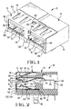
- Connector 10 of FIGS. 1 to 5 includes a shell 12 mounted on a housing 14, and has a mating face 16 and a board mounting face 18.
- Two arrays of discrete contact members 20 are provided associated with two mating portions 30 of the connector, positioned side-by-side along the mating face, with each mating portion for mating with a plug portion of a respective mating connector at an input/output port of an electronic apparatus.
- Each array of contacts may include for example, signal contacts, a power contact and a ground contact.
- Connector 10 is adapted to be mounted onto a circuit board and to be used at an input/output port having a pair of cutouts through a panel of the apparatus for insertion therethrough of respective mating connectors, and shell 12 provides shielding of the connector at the cutouts.
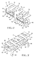
- Discrete contacts 20 are seen in FIGS. 2 and 3 to each have a spring arm contact section 22 extending forwardly from a body section 24, and transition sections 26 extending rearwardly therefrom to a post section 28 depending from a right angle bend to extend beyond board-mounting face 18 to be insertable into through-holes of a circuit board (not shown). Transition sections 26 are angled to position the post sections 28 in a single row spaced apart a regular spacing distance through positioning grooves (FIG. 5). Body sections 24 are shown to preferably include retention barbs to retentively engage side walls of passageways through the housing upon contact insertion.
- Housing 14 is seen in FIGS. 2 and 3 to provide a pair of plug-receiving cavities 32 at respective mating portions 30, extending rearwardly from mating face 16.
- Upper surface of housing 14 includes recesses 34 in communication with respective cavities 32.
- a divider wall 36 is positioned medially across each cavity 32 and opposed to recess 34, dividing the cavity into upper and lower portions 40,42.
- Contact arms 22 of the discrete contacts 20 are disposed in the lower cavity portions 42 and in channels 44 along the bottom surface 46 of divider wall 36, with free ends 48 trapped under lip 50 at the front end of divider wall 36 while permitting arcuate contact sections 52 to extend into lower cavity portion 42 to be engaged by complementary contacts of a mating connector (not shown) and deflected upwardly toward divider wall 36. It is seen that the housing provides the surfaces engaged by a mating plug connector inserted into a respective cavity to facilitate positioning and guiding the plug connector to full mating.
- Housing 14 includes a bottom wall 54 along the board mounting face extending beneath both lower cavity portions 42, and recesses 56 are formed extending from lower cavity portions 42 to inner surface 58 of bottom wall 54. Pairs of guide channels 60 extend laterally outwardly from recesses 56 and along inner surface 58.
- Shell 12 is stamped and formed of a unitary piece from a sheet metal blank to have an upper wall 62 and a lower wall 64 extending rearwardly from front wall 66. Apertures 68 are provided through front wall 66 associated with the two mating portions 30.
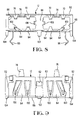
- a pair of first spring arms 70 extend forwardly from a rear section of upper wall 62 and are angled downwardly to extend into one of recesses 34 toward and preferably biased against the upper surface of divider wall 36, with an upwardly angled free end 72 adapted to be engaged by a front plug end of a mating connector for upward deflection during connector mating, and thereafter be biased against a top surface of the conductive shell of the mating plug connector (not shown) during mating and finally seating within recesses therealong to establish retention of the connectors in a mated condition.
- Preferably free ends 72 are appropriately shaped for latching by being bent so as to effectively define rearwardly facing retention surfaces adapted to latchingly engage an adjacent oppositely facing side wall of a respective recess into
- a primary shell-to-housing retention mechanism is provided in the form of a latching projection 80 extending upwardly from the top surface of housing 14 between recesses 34, latchingly received into an aperture 82 in upper shell wall 62.
- Lower shell wall 64 is adapted to be received into housing 14 above a bottom housing wall, thus being insulated from any circuits of a circuit board onto which connector 10 is mounted; such insulation permits minimized spacing between the connector mounting face and the circuit board.
- Lower shell wall 64 comprises a pair of wall sections 84 associated with respective ones of lower cavity portions 42, and side portions 86 thereof are received along guide channels 60. Rear end sections 88 of lower shell wall sections 84 are received into a slot 90 extending rearwardly from lower cavity portion 42 (FIG. 2).
- lower shell wall sections 84 include retention barbs 92 extending outwardly from side edges thereof to bite into and retentively engage lateral walls of guide channels 60 to assist in preventing forward movement of shell 12 with respect to housing 14 during in-service use when connector 10 is being unmated from the plug connector.
- a pair of second spring arms 94 extend forwardly from a rear section of each lower shell wall section 84 and upwardly into both lower cavity portions 42 opposed and spaced from contact sections 52 of signal contacts 20, thus being adapted to assist first spring arms 70 in retaining a plug connector within the plug-receiving cavity upon mating, by appropriately shaped free ends entering recesses into the bottom surface of the plug connector.
- Board-mounting ground contacts or legs 96 depend from lower shell wall sections 84 along an outer side edge thereof to be inserted into through-holes of a circuit board (not shown) upon connector mounting thereto; slots 98 in bottom housing wall 54 extend rearwardly from mating face 16 for receipt of board-mounting legs 96 when shell 12 is being assembled to the housing, best seen in FIG. 4.
- Front wall 66 provides shielding from the immediate periphery of each plug-receiving cavity entrance to beyond the periphery of a correspondingly dimensioned panel cutout associated with each cavity, thus providing enhanced shielding of the mating interface at the cutout.
- front wall 66 of shell 12 includes several lances 102,104 depending from a lower edge 106 and angled slightly forwardly, engageable with wall surfaces of the panel of an electronic apparatus at an input/output port thereof to define ground connections therewith when mounted in abutment with the panel wall.
- Central lance 102 is located centrally and between lower wall sections 84, and outer lances 104 are formed outwardly of the outer edges of lower wall sections 84, all so that shell 12 may be formed from a single sheet of metal to define all necessary and advantageous features thereof.
- a shell-engaging finger 108 extending rearwardly along a channel 110 from front shell wall 66 along a medial wall 112 of the housing between the lower cavity portions 42, with the fingers 108 angled slightly outwardly from the medial wall to assuredly engage side surfaces of the conductive shells surrounding plug portions of mating connectors (not shown).
- side walls may easily be formed from the blank from which the shell member of the present invention is formed, if additional side wall connector shielding is desired, without interfering with any of the retention or grounding sections of the shell. It may also be seen that additional panel-engaging fingers could similarly be formed along side edges of the front wall. Other such variations and modifications may be made that are within the scope of the claims.
Landscapes
- Details Of Connecting Devices For Male And Female Coupling (AREA)
Applications Claiming Priority (3)
| Application Number | Priority Date | Filing Date | Title |
|---|---|---|---|
| US08/601,636 US5685739A (en) | 1996-02-14 | 1996-02-14 | Shielded electrical connector |
| US601636 | 1996-02-14 | ||
| PCT/US1997/002490 WO1997030491A1 (en) | 1996-02-14 | 1997-02-14 | Shielded electrical connector |
Publications (2)
| Publication Number | Publication Date |
|---|---|
| EP0880808A1 EP0880808A1 (en) | 1998-12-02 |
| EP0880808B1 true EP0880808B1 (en) | 2000-05-24 |
Family
ID=24408212
Family Applications (1)
| Application Number | Title | Priority Date | Filing Date |
|---|---|---|---|
| EP97906652A Expired - Lifetime EP0880808B1 (en) | 1996-02-14 | 1997-02-14 | Shielded electrical connector |
Country Status (8)
| Country | Link |
|---|---|
| US (1) | US5685739A (zh) |
| EP (1) | EP0880808B1 (zh) |
| JP (1) | JP2001501015A (zh) |
| CN (1) | CN1211348A (zh) |
| AU (1) | AU2129297A (zh) |
| DE (1) | DE69702123T2 (zh) |
| TW (1) | TW349279B (zh) |
| WO (1) | WO1997030491A1 (zh) |
Families Citing this family (60)
| Publication number | Priority date | Publication date | Assignee | Title |
|---|---|---|---|---|
| DE19621614C1 (de) * | 1996-05-30 | 1997-12-18 | Itt Cannon Gmbh | Steckverbinder |
| US6077120A (en) * | 1996-09-06 | 2000-06-20 | The Whitaker Corporation | Shielded connector of interfitting C-shaped shield members on a housing and method for manufacturing the same |
| US6454603B2 (en) * | 1997-03-07 | 2002-09-24 | Berg Technology, Inc. | Shielded connector with integral latching and ground structure |
| US6231403B1 (en) | 1997-03-07 | 2001-05-15 | Berg Technology, Inc. | Apparatus for assembling an electrical connector and method of use |
| US6315620B1 (en) | 1997-04-24 | 2001-11-13 | Seagate Technology Llc | System, method, and device for a pre-loaded straddle mounted connector assembly |
| JP3278050B2 (ja) * | 1997-06-16 | 2002-04-30 | タイコエレクトロニクスアンプ株式会社 | シールド型コネクタ |
| DE19736607C1 (de) * | 1997-08-22 | 1999-07-15 | Dunkel Otto Gmbh | Leiterplattensteckbuchse |
| USD418817S (en) * | 1998-06-02 | 2000-01-11 | Hon Hai Precision Ind. Co., Ltd. | Connector assembly |
| TW405764U (en) | 1998-10-19 | 2000-09-11 | Molex Inc | Connector supporting device |
| JP2000323233A (ja) * | 1999-05-10 | 2000-11-24 | Molex Inc | コネクタ装置 |
| US6444900B1 (en) * | 1999-05-19 | 2002-09-03 | Fci Americas Technology, Inc. | Electromagnetic interference shielding gasket |
| JP2000357550A (ja) * | 1999-06-15 | 2000-12-26 | Fujitsu Takamisawa Component Ltd | 金属板を折り込んで形成された金属板製シェルを有するコネクタ |
| US6394846B1 (en) * | 1999-08-06 | 2002-05-28 | Fci Americas Technology, Inc. | Electrical connector with separate receptacles using common filter |
| US6537084B2 (en) * | 1999-09-30 | 2003-03-25 | Berg Technology, Inc. | Electrical connector with electrical shield having latch and mounting arms |
| US6231390B1 (en) * | 1999-10-21 | 2001-05-15 | Hon Hai Precision Ind. Co., Ltd. | Connector for use in portable phone |
| US6273757B1 (en) | 1999-11-10 | 2001-08-14 | Berg Technology, Inc. | Receptacle with conductive cavity insertion piece inserted thereinto |
| US6533617B1 (en) | 2000-01-07 | 2003-03-18 | J. D'addario & Company, Inc. | Electrical plug connectors |
| US6296525B1 (en) | 2000-01-07 | 2001-10-02 | J. D'addario & Company, Inc. | Electrical plug and jack connectors |
| US6315608B1 (en) * | 2000-03-31 | 2001-11-13 | Molex Incorporated | Channel isolation shield |
| TW450449U (en) * | 2000-05-16 | 2001-08-11 | Hon Hai Prec Ind Co Ltd | Electrical connector |
| US6347960B1 (en) * | 2000-06-29 | 2002-02-19 | L&K Precision Industry Co., Ltd. | Module connector |
| TW540187B (en) * | 2000-09-29 | 2003-07-01 | Tyco Electronics Amp Kk | Electrical connector assembly and female connector |
| US6585540B2 (en) * | 2000-12-06 | 2003-07-01 | Pulse Engineering | Shielded microelectronic connector assembly and method of manufacturing |
| WO2002076169A1 (en) * | 2001-03-16 | 2002-09-26 | Laird Technologies, Inc. | Shielding cover for fiber optic transceiver |
| JP3761428B2 (ja) * | 2001-07-04 | 2006-03-29 | 日本航空電子工業株式会社 | コネクタ |
| US6835091B2 (en) * | 2001-07-06 | 2004-12-28 | Fci Americas Technology, Inc. | Universal serial bus electrical connector |
| JP3755652B2 (ja) * | 2002-02-18 | 2006-03-15 | タイコエレクトロニクスアンプ株式会社 | シールドコネクタ組立体 |
| CN100566032C (zh) * | 2002-05-24 | 2009-12-02 | Fci公司 | 改进的插座 |
| TW551650U (en) | 2002-12-10 | 2003-09-01 | Hon Hai Prec Ind Co Ltd | A cable connector assembly |
| EP1557908B1 (en) * | 2004-01-05 | 2007-08-15 | Sumitomo Wiring Systems, Ltd. | A connector |
| CN2728007Y (zh) * | 2004-08-05 | 2005-09-21 | 富士康(昆山)电脑接插件有限公司 | 电连接器 |
| CN2735587Y (zh) * | 2004-08-17 | 2005-10-19 | 富士康(昆山)电脑接插件有限公司 | 电源连接器 |
| JP4551868B2 (ja) * | 2005-12-28 | 2010-09-29 | 日本航空電子工業株式会社 | コネクタ |
| US7455554B2 (en) | 2005-12-28 | 2008-11-25 | Molex Incorporated | EMI shroud with bidirectional contact members |
| CN1992447A (zh) * | 2005-12-29 | 2007-07-04 | 富士康(昆山)电脑接插件有限公司 | 电连接器组件 |
| CN2932726Y (zh) * | 2006-04-13 | 2007-08-08 | 富士康(昆山)电脑接插件有限公司 | 电连接器 |
| US20080130207A1 (en) * | 2006-12-05 | 2008-06-05 | Methode Electronics, Inc. | USB connector assembly |
| WO2008109109A1 (en) * | 2007-03-06 | 2008-09-12 | Tyco Electronics Corporation | High voltage shielded electrical connector assembly |
| US7578705B2 (en) * | 2007-08-10 | 2009-08-25 | Hon Hai Precision Ind. Co., Ltd. | Electrical connector with improved contacts arrangement |
| US8004406B2 (en) * | 2007-11-06 | 2011-08-23 | Bleckmann Frederick A | Pliable material tag using a lanyard or a portion of a garment |
| TWM330607U (en) * | 2007-11-16 | 2008-04-11 | Wonten Technology Co Ltd | Electric connector |
| CN201142458Y (zh) * | 2007-12-21 | 2008-10-29 | 富士康(昆山)电脑接插件有限公司 | 电连接器 |
| JP4985498B2 (ja) * | 2008-03-20 | 2012-07-25 | 住友電装株式会社 | 基板用コネクタ |
| CN101728686A (zh) * | 2008-10-21 | 2010-06-09 | 鸿富锦精密工业(深圳)有限公司 | 连接器 |
| US7614920B1 (en) | 2008-11-17 | 2009-11-10 | Hon Hai Precision Ind. Co., Ltd. | Electrical connector with improved mating port for high speed signal transmission |
| US8335087B2 (en) | 2008-12-22 | 2012-12-18 | Huawei Device Co., Ltd. | Method and apparatus for improving radio performance of wireless data terminal device |
| HK1125531A2 (en) * | 2008-12-24 | 2009-08-07 | Leung Shiu Ming | Action simulation device and method |
| US8002572B2 (en) * | 2009-07-15 | 2011-08-23 | Luxi Electronics Corp. | HDMI DIY field termination products |
| US7699663B1 (en) * | 2009-07-29 | 2010-04-20 | Hon Hai Precision Ind. Co., Ltd. | Electrical connector with improved grounding contact |
| US8096834B2 (en) * | 2009-08-12 | 2012-01-17 | Giga-Byte Technology Co., Ltd. | Connector with electromagnetic conduction mechanism |
| US8298016B2 (en) * | 2009-08-12 | 2012-10-30 | Giga-Byte Technology Co., Ltd. | Connector having a shield with with spring arms in lengthwise and crosswise directions |
| JP5334753B2 (ja) * | 2009-08-28 | 2013-11-06 | 矢崎総業株式会社 | シールドコネクタ |
| TWI508392B (zh) * | 2010-03-26 | 2015-11-11 | Hosiden Corp | Shields, connectors and electronic machines |
| US8388385B2 (en) * | 2010-08-31 | 2013-03-05 | Apple Inc. | Connector assembly |
| US8992263B2 (en) * | 2012-08-01 | 2015-03-31 | National Instruments Corporation | Serial bus receptacle with exterior socket clamping |
| EP3134945B1 (en) | 2014-04-23 | 2019-06-12 | TE Connectivity Corporation | Electrical connector with shield cap and shielded terminals |
| KR101797951B1 (ko) | 2014-06-02 | 2017-11-15 | 니혼 고꾸 덴시 고교 가부시끼가이샤 | 커넥터 |
| JP5905941B2 (ja) * | 2014-08-29 | 2016-04-20 | 日本航空電子工業株式会社 | コネクタ |
| JP6278841B2 (ja) * | 2014-06-02 | 2018-02-14 | 日本航空電子工業株式会社 | コネクタ |
| JP6886910B2 (ja) * | 2017-11-28 | 2021-06-16 | 日本航空電子工業株式会社 | コネクタ組立体 |
Family Cites Families (17)
| Publication number | Priority date | Publication date | Assignee | Title |
|---|---|---|---|---|
| JPS5048984U (zh) * | 1973-09-03 | 1975-05-14 | ||
| US4457576A (en) * | 1982-12-17 | 1984-07-03 | Amp Incorporated | One piece metal shield for an electrical connector |
| US4582384A (en) * | 1984-05-04 | 1986-04-15 | Amp Incorporated | Overmolded shielded connector |
| US4756695A (en) * | 1986-06-13 | 1988-07-12 | Amp Incorporated | Local area network interface |
| JPS6321772A (ja) * | 1986-07-15 | 1988-01-29 | ヒロセ電機株式会社 | 電気コネクタ用シールドケース |
| JPH0339901Y2 (zh) * | 1987-04-30 | 1991-08-22 | ||
| US5035651A (en) * | 1988-11-25 | 1991-07-30 | Molex Incorporated | Miniature circular DIN connector |
| JPH0716312Y2 (ja) * | 1989-02-28 | 1995-04-12 | ホシデン株式会社 | コネクタ |
| JPH0722064Y2 (ja) * | 1989-12-04 | 1995-05-17 | ホシデン株式会社 | コネクタ |
| US5158481A (en) * | 1991-09-27 | 1992-10-27 | Amp Incorporated | Shielded electrical connector with torsioned shield interconnect |
| US5161997A (en) * | 1991-10-11 | 1992-11-10 | Amp Incorporated | Hardwareless panel retention for shielded connector |
| US5267882A (en) * | 1992-12-10 | 1993-12-07 | The Whitaker Corporation | Set of keyed electrical connectors |
| NL9300971A (nl) * | 1993-06-04 | 1995-01-02 | Framatome Connectors Belgium | Connectorsamenstel voor printkaarten. |
| US5376011A (en) * | 1993-06-11 | 1994-12-27 | The Whitaker Corporation | Integral shell for tandem circuit card connectors |
| NL9400321A (nl) * | 1994-03-03 | 1995-10-02 | Framatome Connectors Belgium | Connector voor een kabel voor hoogfrequente signalen. |
| US5399105A (en) * | 1994-04-29 | 1995-03-21 | The Whitaker Corporation | Conductive shroud for electrical connectors |
| US5496195A (en) * | 1995-03-13 | 1996-03-05 | The Whitaker Corporation | High performance shielded connector |
-
1996
- 1996-02-14 US US08/601,636 patent/US5685739A/en not_active Expired - Lifetime
-
1997
- 1997-02-14 CN CN97192312A patent/CN1211348A/zh active Pending
- 1997-02-14 JP JP09529565A patent/JP2001501015A/ja active Pending
- 1997-02-14 DE DE69702123T patent/DE69702123T2/de not_active Expired - Lifetime
- 1997-02-14 EP EP97906652A patent/EP0880808B1/en not_active Expired - Lifetime
- 1997-02-14 AU AU21292/97A patent/AU2129297A/en not_active Abandoned
- 1997-02-14 WO PCT/US1997/002490 patent/WO1997030491A1/en active IP Right Grant
- 1997-03-05 TW TW086102621A patent/TW349279B/zh not_active IP Right Cessation
Also Published As
| Publication number | Publication date |
|---|---|
| DE69702123D1 (de) | 2000-06-29 |
| JP2001501015A (ja) | 2001-01-23 |
| US5685739A (en) | 1997-11-11 |
| DE69702123T2 (de) | 2001-01-25 |
| EP0880808A1 (en) | 1998-12-02 |
| CN1211348A (zh) | 1999-03-17 |
| AU2129297A (en) | 1997-09-02 |
| TW349279B (en) | 1999-01-01 |
| WO1997030491A1 (en) | 1997-08-21 |
Similar Documents
| Publication | Publication Date | Title |
|---|---|---|
| EP0880808B1 (en) | Shielded electrical connector | |
| CN109962353B (zh) | 卡缘连接器 | |
| US5676569A (en) | Holder for several electrical connectors | |
| US5865646A (en) | Connector shield with integral latching and ground structure | |
| EP0907989B1 (en) | Shielded electrical connector | |
| US5755595A (en) | Shielded electrical connector | |
| US8961235B2 (en) | Electrical connector with improved mating member having anti-mismating portion for preventing incorrect insertion | |
| EP0928049B1 (en) | Stacked lan connector | |
| US5380223A (en) | High density electrical connector | |
| US5915976A (en) | High speed connector | |
| US9450355B2 (en) | USB plug connector and method for manufacturing the same | |
| US7086889B2 (en) | Interlocking member for an electrical connector | |
| US6210218B1 (en) | Electrical connector | |
| US6241556B1 (en) | Retention member for connector | |
| EP0858134B1 (en) | Electrical connector assembly | |
| US6454603B2 (en) | Shielded connector with integral latching and ground structure | |
| WO1998009352A1 (en) | Ultra low profile board-mounted modular jack | |
| US5967846A (en) | Shields for electrical connector mated pair | |
| US6200161B1 (en) | Stacked electrical connector | |
| US6893272B2 (en) | Electrical connector assembly having improved grounding means | |
| EP0850499B1 (en) | Shielded electrical connector | |
| US7470127B2 (en) | Electrical connector assembly | |
| US6227874B1 (en) | Electronic card connection system | |
| CN112636044B (zh) | 连接器 | |
| CN114336178A (zh) | 电连接器 |
Legal Events
| Date | Code | Title | Description |
|---|---|---|---|
| PUAI | Public reference made under article 153(3) epc to a published international application that has entered the european phase |
Free format text: ORIGINAL CODE: 0009012 |
|
| 17P | Request for examination filed |
Effective date: 19980824 |
|
| AK | Designated contracting states |
Kind code of ref document: A1 Designated state(s): DE FR GB |
|
| 17Q | First examination report despatched |
Effective date: 19990610 |
|
| GRAG | Despatch of communication of intention to grant |
Free format text: ORIGINAL CODE: EPIDOS AGRA |
|
| GRAG | Despatch of communication of intention to grant |
Free format text: ORIGINAL CODE: EPIDOS AGRA |
|
| GRAH | Despatch of communication of intention to grant a patent |
Free format text: ORIGINAL CODE: EPIDOS IGRA |
|
| RIC1 | Information provided on ipc code assigned before grant |
Free format text: 7H 01R 12/16 A, 7H 01R 13/652 B |
|
| GRAH | Despatch of communication of intention to grant a patent |
Free format text: ORIGINAL CODE: EPIDOS IGRA |
|
| GRAA | (expected) grant |
Free format text: ORIGINAL CODE: 0009210 |
|
| AK | Designated contracting states |
Kind code of ref document: B1 Designated state(s): DE FR GB |
|
| REF | Corresponds to: |
Ref document number: 69702123 Country of ref document: DE Date of ref document: 20000629 |
|
| ET | Fr: translation filed | ||
| PLBE | No opposition filed within time limit |
Free format text: ORIGINAL CODE: 0009261 |
|
| STAA | Information on the status of an ep patent application or granted ep patent |
Free format text: STATUS: NO OPPOSITION FILED WITHIN TIME LIMIT |
|
| 26N | No opposition filed | ||
| REG | Reference to a national code |
Ref country code: GB Ref legal event code: IF02 |
|
| PGFP | Annual fee paid to national office [announced via postgrant information from national office to epo] |
Ref country code: GB Payment date: 20130227 Year of fee payment: 17 Ref country code: DE Payment date: 20130227 Year of fee payment: 17 Ref country code: FR Payment date: 20130311 Year of fee payment: 17 |
|
| REG | Reference to a national code |
Ref country code: DE Ref legal event code: R119 Ref document number: 69702123 Country of ref document: DE |
|
| REG | Reference to a national code |
Ref country code: DE Ref legal event code: R079 Ref document number: 69702123 Country of ref document: DE Free format text: PREVIOUS MAIN CLASS: H01R0012160000 Ipc: H01R0012500000 |
|
| GBPC | Gb: european patent ceased through non-payment of renewal fee |
Effective date: 20140214 |
|
| REG | Reference to a national code |
Ref country code: FR Ref legal event code: ST Effective date: 20141031 |
|
| REG | Reference to a national code |
Ref country code: DE Ref legal event code: R119 Ref document number: 69702123 Country of ref document: DE Effective date: 20140902 Ref country code: DE Ref legal event code: R079 Ref document number: 69702123 Country of ref document: DE Free format text: PREVIOUS MAIN CLASS: H01R0012160000 Ipc: H01R0012500000 Effective date: 20141022 |
|
| PG25 | Lapsed in a contracting state [announced via postgrant information from national office to epo] |
Ref country code: GB Free format text: LAPSE BECAUSE OF NON-PAYMENT OF DUE FEES Effective date: 20140214 Ref country code: DE Free format text: LAPSE BECAUSE OF NON-PAYMENT OF DUE FEES Effective date: 20140902 Ref country code: FR Free format text: LAPSE BECAUSE OF NON-PAYMENT OF DUE FEES Effective date: 20140228 |