EP0879980A2 - Schlauchverschraubung - Google Patents
Schlauchverschraubung Download PDFInfo
- Publication number
- EP0879980A2 EP0879980A2 EP98106918A EP98106918A EP0879980A2 EP 0879980 A2 EP0879980 A2 EP 0879980A2 EP 98106918 A EP98106918 A EP 98106918A EP 98106918 A EP98106918 A EP 98106918A EP 0879980 A2 EP0879980 A2 EP 0879980A2
- Authority
- EP
- European Patent Office
- Prior art keywords
- clamping body
- hose
- angle
- clamping
- screw connection
- Prior art date
- Legal status (The legal status is an assumption and is not a legal conclusion. Google has not performed a legal analysis and makes no representation as to the accuracy of the status listed.)
- Granted
Links
- 230000008878 coupling Effects 0.000 title abstract 2
- 238000010168 coupling process Methods 0.000 title abstract 2
- 238000005859 coupling reaction Methods 0.000 title abstract 2
- 239000004696 Poly ether ether ketone Substances 0.000 claims abstract description 7
- 229920002530 polyetherether ketone Polymers 0.000 claims abstract description 7
- 229920001343 polytetrafluoroethylene Polymers 0.000 claims abstract description 5
- 239000004810 polytetrafluoroethylene Substances 0.000 claims abstract description 5
- 239000004033 plastic Substances 0.000 claims abstract description 3
- -1 polytetrafluoroethylene Polymers 0.000 claims description 2
- 230000037431 insertion Effects 0.000 claims 1
- 238000003780 insertion Methods 0.000 claims 1
- 239000000463 material Substances 0.000 description 4
- 230000000694 effects Effects 0.000 description 2
- 239000011324 bead Substances 0.000 description 1
- 230000005540 biological transmission Effects 0.000 description 1
- 238000001816 cooling Methods 0.000 description 1
- 230000005489 elastic deformation Effects 0.000 description 1
- 230000000149 penetrating effect Effects 0.000 description 1
- 230000035515 penetration Effects 0.000 description 1
Images

Classifications
-
- F—MECHANICAL ENGINEERING; LIGHTING; HEATING; WEAPONS; BLASTING
- F16—ENGINEERING ELEMENTS AND UNITS; GENERAL MEASURES FOR PRODUCING AND MAINTAINING EFFECTIVE FUNCTIONING OF MACHINES OR INSTALLATIONS; THERMAL INSULATION IN GENERAL
- F16L—PIPES; JOINTS OR FITTINGS FOR PIPES; SUPPORTS FOR PIPES, CABLES OR PROTECTIVE TUBING; MEANS FOR THERMAL INSULATION IN GENERAL
- F16L19/00—Joints in which sealing surfaces are pressed together by means of a member, e.g. a swivel nut, screwed on, or into, one of the joint parts
- F16L19/08—Joints in which sealing surfaces are pressed together by means of a member, e.g. a swivel nut, screwed on, or into, one of the joint parts with metal rings which bite into the wall of the pipe
- F16L19/10—Joints in which sealing surfaces are pressed together by means of a member, e.g. a swivel nut, screwed on, or into, one of the joint parts with metal rings which bite into the wall of the pipe the profile of the ring being altered
- F16L19/103—Joints in which sealing surfaces are pressed together by means of a member, e.g. a swivel nut, screwed on, or into, one of the joint parts with metal rings which bite into the wall of the pipe the profile of the ring being altered with more than one ring per pipe end being used
-
- F—MECHANICAL ENGINEERING; LIGHTING; HEATING; WEAPONS; BLASTING
- F16—ENGINEERING ELEMENTS AND UNITS; GENERAL MEASURES FOR PRODUCING AND MAINTAINING EFFECTIVE FUNCTIONING OF MACHINES OR INSTALLATIONS; THERMAL INSULATION IN GENERAL
- F16L—PIPES; JOINTS OR FITTINGS FOR PIPES; SUPPORTS FOR PIPES, CABLES OR PROTECTIVE TUBING; MEANS FOR THERMAL INSULATION IN GENERAL
- F16L33/00—Arrangements for connecting hoses to rigid members; Rigid hose-connectors, i.e. single members engaging both hoses
- F16L33/22—Arrangements for connecting hoses to rigid members; Rigid hose-connectors, i.e. single members engaging both hoses with means not mentioned in the preceding groups for gripping the hose between inner and outer parts
- F16L33/223—Arrangements for connecting hoses to rigid members; Rigid hose-connectors, i.e. single members engaging both hoses with means not mentioned in the preceding groups for gripping the hose between inner and outer parts the sealing surfaces being pressed together by means of a member, e.g. a swivel nut, screwed on or into one of the joint parts
- F16L33/224—Arrangements for connecting hoses to rigid members; Rigid hose-connectors, i.e. single members engaging both hoses with means not mentioned in the preceding groups for gripping the hose between inner and outer parts the sealing surfaces being pressed together by means of a member, e.g. a swivel nut, screwed on or into one of the joint parts a clamping ring being arranged between the threaded member and the connecting member
-
- F—MECHANICAL ENGINEERING; LIGHTING; HEATING; WEAPONS; BLASTING
- F16—ENGINEERING ELEMENTS AND UNITS; GENERAL MEASURES FOR PRODUCING AND MAINTAINING EFFECTIVE FUNCTIONING OF MACHINES OR INSTALLATIONS; THERMAL INSULATION IN GENERAL
- F16L—PIPES; JOINTS OR FITTINGS FOR PIPES; SUPPORTS FOR PIPES, CABLES OR PROTECTIVE TUBING; MEANS FOR THERMAL INSULATION IN GENERAL
- F16L47/00—Connecting arrangements or other fittings specially adapted to be made of plastics or to be used with pipes made of plastics
- F16L47/04—Connecting arrangements or other fittings specially adapted to be made of plastics or to be used with pipes made of plastics with a swivel nut or collar engaging the pipe
Definitions
- the present invention relates to a hose fitting for in particular flexible hoses and rigid pipes.
- the screw connection consists of one Screw body with a molded nozzle on which the fastening hose is pushed.
- the hose is from a circlip comprises of a union nut in one of the spout adjacent cone-shaped socket is pressed and thereby pinches the hose, see e.g. B. DE 42 11 498 A1.
- the clamping element used for this can also be formed in several parts, such. B. DE-OS 22 13 334.
- the present invention has therefore set itself the task of such To further develop screw connections in such a way that they can also be used on higher ones Temperatures and also after a variety of temperature changes Hose holds securely.
- the division of the clamping body ensures that its parts from different Materials with different strength values are formed can be d. H. the tasks on the outer and inner sprag areas can therefore be different.
- the clamping edge of the nozzle is preferably approximately in the middle to the inner contact surface of the inner sprag on the hose.
- the nozzle is preferably also conical, whereby the introduction of force into the screw body is improved.
- the second outer clamping body part has an inward direction of the hose Lip, which is supported on the funnel surface of the inner clamping body, so that when screwing the union nut into the hose material penetrates. There is therefore also a free space at the lip.
- both the hose is pressed by the inner clamping body as well as clawing with the fasteners the lip of the outer sprag. From the overall effect of the linear Force transmission into the inner clamping body together and clawing through the lip is vibration and temperature independent Behavior of the screw connection.
- the outer clamping body consists of polyether ether ketone (PEEK) and the inner preferably made of polytetrafluoroethylene (PTFE).
- PEEK polyether ether ketone
- PTFE polytetrafluoroethylene
- Nozzle which is in particular conical and an opening angle ⁇ of about 25-35 °, preferably 30 °, with the inner clamping body has a lateral angle ⁇ of approximately 28-45 °, preferably 37 °.
- the inner jacket body has an upper (outer) funnel into which the second - outer - clamping body is inserted, through the force applied by the union nut whose lip is constricted axially.
- This angle is ⁇ 85 to 95 °, preferably 90 °.
- the lip closes an outer one
- An angle of about 85-95 °, preferably 90 °, with the inner cutting lip angle ⁇ is approximately 55-65 °, preferably 60 °.
- the lip itself is preferably bent off from the clamping body, wherein the inner surface is cylindrical, so that when pressed in The inner surface can also be placed flat on the hose. This is particularly the depth of penetration of the lip in the hose can be limited to prevent it from being destroyed to protect, so that this as it were as a final deflection for the cap nut serves.
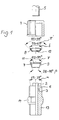
- Figure 1 shows the hose 5 starting from above and below the union nut 4 with an internal thread (not shown). Below this, the outer clamping body 8 is shown, which carries the lip 12 at the bottom, which penetrates into the tube material when screwed on.
- the cross section of the outer clamping body 8 is shown enlarged in FIG.
- This first clamping body 8 engages in the funnel 11 of the inner clamping body 7 a, the funnel angle ⁇ of the inner clamping body therefore corresponds to that ⁇ ' of the outer clamping body and is 85 - 95 °.
- the cutting lip 12 is on the Inside enclosed by the lip angle ⁇ , this is 55 - 65 °.
- the Lip 12 is bent off from the clamping body 8.
- the screw body 1 has a grommet 2, on the radially outward foot side a stop ring surface 3 connects.
- the hose 5 is on the spout 2 pushed and lies on the stop ring surface 3.
- the nozzle 6 follows, which preferably follows (in the illustration) extended at the top with an opening angle ⁇ of 25 - 35 °.
- the screw body 1 has an external thread 13 and a hexagon 14 for screwing with a tap. It can also have an internal thread and the like Hexagon.
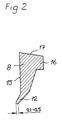
- Figure 2 shows the special shape of the outer (upper) clamping body 8 made of PEEK.
- This has a cylindrical surface 15 aligned parallel to the central axis of the screw connection, from which the lip 12 penetrating into the hose under its elastic deformation is bent. The corresponding angles are shown in Figure 1.
- the upper region of the clamping body advantageously has a bulge 16 and has a bevel 17, so that in this case too, the force introduction by the union nut is essentially linear and defined along the cylinder surface 15 with a vector.
- Figure 3 illustrates the assembly of the parts with the screw body 1.
- the hose 5 is pushed over the spout 2 to the stop surface 3 and secured by the screw connection with the union nut 4 and the clamping body 7, 8.
Landscapes
- Engineering & Computer Science (AREA)
- General Engineering & Computer Science (AREA)
- Mechanical Engineering (AREA)
- Joints That Cut Off Fluids, And Hose Joints (AREA)
- Joints With Pressure Members (AREA)
- Examining Or Testing Airtightness (AREA)
- Forklifts And Lifting Vehicles (AREA)
- Rigid Pipes And Flexible Pipes (AREA)
- Joints Allowing Movement (AREA)
- Infusion, Injection, And Reservoir Apparatuses (AREA)
Abstract
Description
- Figur 1
- die Verschraubung in Explosionsdarstellung,
- Figur 2
- den äußeren Klemmkörper und
- Figur 3
- diese in zusammengebautem Zustand.
- 1
- Verschraubungskörper
- 2
- Tülle
- 3
- Anschlagringfläche
- 4
- Überwurfmutter
- 5
- Schlauch
- 6
- Stutzen
- 7
- innerer Klemmkörper
- 8
- äußerer Klemmkörper
- 9
- äußere Mantelfläche
- 10
- Freiraum
- 11
- Trichter
- 12
- Lippe
- 13
- Außengewinde
- 14
- Sechskant
- 15
- Zylinderfläche
- 16
- Wulst
- 17
- Abschrägung
- α
- Öffnungswinkel
- β
- Mantelwinkel
- γ
- Trichterwinkel
- δ
- Schneidlippenwinkel
Claims (7)
- Schlauchverschraubung aus Kunststoff für flexible Schläuche und starre Rohre (5), bestehend aus einem Verschraubungskörper (1) mit einem Außengewinde und darauf aufschraubbarer Überwurfmutter (4) und einer inneren Tülle (2), auf die der Schlauch (5) aufschiebbar ist, an welche bodenseitig eine Anschlagringfläche (3) angeformt ist, an die sich ein Stutzen mit einer kegeligen Erweiterung (6) anschließt, in den ein diesen überragendes Klemmelement einführbar ist, der mit der Überwurfmutter (4) zusammenwirkt, gekennzeichnet durch die folgenden Merkmale:a) das Klemmelement besteht aus einem ersten (7) und einem zweiten (8), axial hintereinander angeordneten Klemmkörper,b) der erste, in Einschubrichtung gesehen vorne angeordnete Klemmkörper (7) weist eine kegelige Mantelfläche, deren Mantelwinkel β größer ist als ein Öffnungswinkel α der kegeligen Erweiterung des Stutzens (6), undc) an seiner Rückseite einen Trichter (11) auf, gegen den der zweite Klemmkörper (8) anliegt,d) der zweite Klemmkörper (8) besitzt eine radial einwärts gerichtete Lippe (12).
- Schlauchverschraubung nach Anspruch 1, dadurch gekennzeichnet, daß der äußere Klemmkörper (8) aus Polyetheretherketon (PEEK) gefertigt ist.
- Schlauchverschraubung nach Anspruch 1, dadurch gekennzeichnet, daß der innere Klemmkörper aus Polytetrafluorethylen (PTFE) hergestellt ist.
- Schlauchverschraubung nach einem der Ansprüche 1 bis 3, dadurch gekennzeichnet, daß der Stutzen (6) einen Öffnungswinkel α von etwa 25 - 35° und der innere Klemmkörper einen Mantelwinkel β von etwa 28 - 45° besitzen.
- Schlauchverschraubung nach einem der Ansprüche 1 bis 4, dadurch gekennzeichnet, daß der Trichterwinkel γ des inneren Klemmkörpers (7) etwa 85 - 95° aufweist.
- Schlauchverschraubung nach einem der Ansprüche 1 bis 5, dadurch gekennzeichnet, daß der Schneidlippenwinkel δ etwa 55 - 65° beträgt.
- Schlauchverschraubung nach einem der Ansprüche 1 bis 6, dadurch gekennzeichnet, daß die Lippe (12) des äußeren Klemmkörpers (8) von diesem abgeknickt ist, wobei die Innenfläche des Klemmkörpers zylindrisch ist.
Applications Claiming Priority (2)
| Application Number | Priority Date | Filing Date | Title |
|---|---|---|---|
| DE19721179A DE19721179C1 (de) | 1997-05-21 | 1997-05-21 | Schlauchverschraubung |
| DE19721179 | 1997-05-21 |
Publications (3)
| Publication Number | Publication Date |
|---|---|
| EP0879980A2 true EP0879980A2 (de) | 1998-11-25 |
| EP0879980A3 EP0879980A3 (de) | 2001-02-28 |
| EP0879980B1 EP0879980B1 (de) | 2003-10-15 |
Family
ID=7830040
Family Applications (1)
| Application Number | Title | Priority Date | Filing Date |
|---|---|---|---|
| EP98106918A Expired - Lifetime EP0879980B1 (de) | 1997-05-21 | 1998-04-16 | Schlauchverschraubung |
Country Status (6)
| Country | Link |
|---|---|
| EP (1) | EP0879980B1 (de) |
| AT (1) | ATE252209T1 (de) |
| DE (2) | DE19721179C1 (de) |
| DK (1) | DK0879980T3 (de) |
| ES (1) | ES2208994T3 (de) |
| PT (1) | PT879980E (de) |
Cited By (12)
| Publication number | Priority date | Publication date | Assignee | Title |
|---|---|---|---|---|
| US7066496B2 (en) | 2001-02-06 | 2006-06-27 | Swagelok Company | Fitting with separable gripping device for pipe and tube |
| US7108288B2 (en) | 2001-02-06 | 2006-09-19 | Swagelok Company | Tube fitting with separable tube gripping ring |
| US7393018B2 (en) | 2001-02-06 | 2008-07-01 | Swagelok Company | Tube fitting for stainless steel tubing |
| DE102006062690A1 (de) | 2005-07-28 | 2008-07-03 | Hidde, Axel R., Dr. | Schlauch-/Rohrverschraubung mit Membranventil |
| US7416225B2 (en) | 2001-02-06 | 2008-08-26 | Swagelok Company | Fitting for metal pipe and tubing |
| EP2447586A1 (de) * | 2010-10-26 | 2012-05-02 | Michael Meier | Schlauchkupplung |
| US10024468B2 (en) | 2014-05-09 | 2018-07-17 | Swagelok Company | Conduit fitting with components adapted for facilitating assembly |
| CN109296858A (zh) * | 2018-11-23 | 2019-02-01 | 中国石油大学(华东) | 一种海洋柔性管接头结构 |
| US10215315B2 (en) | 2008-09-05 | 2019-02-26 | Parker-Hannifin Corporation | Tube compression fitting and flared fitting used with connection body and method of making same |
| DE102018205397A1 (de) | 2018-04-10 | 2019-10-10 | Wmf Group Gmbh | Klemmring für Schlauchverbindungen, den Klemmring umfassende Klemmvorrichtung für Schlauchverbindungen sowie die Klemmvorrichtung umfassende Schlauchverbindung |
| DE102009044807B4 (de) * | 2009-09-15 | 2019-12-24 | Continental Teves Ag & Co. Ohg | Spannringsatz |
| US10584814B2 (en) | 2016-03-23 | 2020-03-10 | Swagelok Company | Conduit fitting with stroke resisting features |
Families Citing this family (3)
| Publication number | Priority date | Publication date | Assignee | Title |
|---|---|---|---|---|
| US7407196B2 (en) | 2003-08-06 | 2008-08-05 | Swagelok Company | Tube fitting with separable tube gripping device |
| RU2258860C1 (ru) * | 2004-02-24 | 2005-08-20 | Геннадий Григорьевич Алексеенко | Шланговое соединение и способ его сборки |
| CN111928045A (zh) * | 2020-07-28 | 2020-11-13 | 泰州市光明电子材料有限公司 | 一种聚四氟乙烯管快速连接件 |
Citations (2)
| Publication number | Priority date | Publication date | Assignee | Title |
|---|---|---|---|---|
| DE2213334A1 (de) | 1971-04-15 | 1972-11-02 | Crawford Fitting Co., Solon, Ohio (V.StA.) | Rohrverbindungsstück |
| DE4211498A1 (de) | 1992-04-06 | 1993-10-07 | Em Technik Gmbh Armaturenbau | Rohrverschraubung für relativ starre Schläuche |
Family Cites Families (8)
| Publication number | Priority date | Publication date | Assignee | Title |
|---|---|---|---|---|
| DE956554C (de) * | 1954-04-30 | 1957-01-17 | Hans Kreidel Jun | Anpassungskegel fuer Schneidring-Rohrverbindungen |
| US3075793A (en) * | 1959-06-03 | 1963-01-29 | Crawford Fitting Co | Packed wedge type coupling having positioning means |
| US3103373A (en) * | 1961-06-29 | 1963-09-10 | Crawford Fitting Co | Controlled phase sequential gripping device |
| GB1146673A (en) * | 1965-08-13 | 1969-03-26 | E E Jeavons & Co Ltd | Improvements in or relating to pipe joints |
| DE1625961C3 (de) * | 1967-10-31 | 1973-11-08 | Einar Bjoern Oslo Christensen | Kupplung zum Anschließen eines starren oder nachgiebigen Rohres an ein Anschlußstuck |
| FR2468826A1 (fr) * | 1979-10-31 | 1981-05-08 | Capri Codec Sa | Raccord pour tuyau de transport de fluide |
| US4304422A (en) * | 1980-02-19 | 1981-12-08 | Gould Inc. | Tube coupling with frangible sleeve |
| DE8031377U1 (de) * | 1980-11-25 | 1981-04-02 | Em-Technik Gmbh Armaturenbau, 6701 Maxdorf | Schlauchverbinder |
-
1997
- 1997-05-21 DE DE19721179A patent/DE19721179C1/de not_active Expired - Lifetime
-
1998
- 1998-04-16 EP EP98106918A patent/EP0879980B1/de not_active Expired - Lifetime
- 1998-04-16 DE DE59809898T patent/DE59809898D1/de not_active Expired - Lifetime
- 1998-04-16 AT AT98106918T patent/ATE252209T1/de active
- 1998-04-16 ES ES98106918T patent/ES2208994T3/es not_active Expired - Lifetime
- 1998-04-16 DK DK98106918T patent/DK0879980T3/da active
- 1998-04-16 PT PT98106918T patent/PT879980E/pt unknown
Patent Citations (2)
| Publication number | Priority date | Publication date | Assignee | Title |
|---|---|---|---|---|
| DE2213334A1 (de) | 1971-04-15 | 1972-11-02 | Crawford Fitting Co., Solon, Ohio (V.StA.) | Rohrverbindungsstück |
| DE4211498A1 (de) | 1992-04-06 | 1993-10-07 | Em Technik Gmbh Armaturenbau | Rohrverschraubung für relativ starre Schläuche |
Cited By (16)
| Publication number | Priority date | Publication date | Assignee | Title |
|---|---|---|---|---|
| US7066496B2 (en) | 2001-02-06 | 2006-06-27 | Swagelok Company | Fitting with separable gripping device for pipe and tube |
| US7108288B2 (en) | 2001-02-06 | 2006-09-19 | Swagelok Company | Tube fitting with separable tube gripping ring |
| US7393018B2 (en) | 2001-02-06 | 2008-07-01 | Swagelok Company | Tube fitting for stainless steel tubing |
| US7416225B2 (en) | 2001-02-06 | 2008-08-26 | Swagelok Company | Fitting for metal pipe and tubing |
| DE102006062690A1 (de) | 2005-07-28 | 2008-07-03 | Hidde, Axel R., Dr. | Schlauch-/Rohrverschraubung mit Membranventil |
| DE102006062690B4 (de) * | 2005-07-28 | 2015-10-29 | Axel R. Hidde | Schlauch-/Rohrverschraubung mit Membranventil |
| US10215315B2 (en) | 2008-09-05 | 2019-02-26 | Parker-Hannifin Corporation | Tube compression fitting and flared fitting used with connection body and method of making same |
| DE102009044807B4 (de) * | 2009-09-15 | 2019-12-24 | Continental Teves Ag & Co. Ohg | Spannringsatz |
| EP2447586A1 (de) * | 2010-10-26 | 2012-05-02 | Michael Meier | Schlauchkupplung |
| US10024468B2 (en) | 2014-05-09 | 2018-07-17 | Swagelok Company | Conduit fitting with components adapted for facilitating assembly |
| US12072044B2 (en) | 2014-05-09 | 2024-08-27 | Swagelok Company | Conduit fitting with components adapted for facilitating assembly |
| US11079046B2 (en) | 2014-05-09 | 2021-08-03 | Swagelok Company | Conduit fitting with components adapted for facilitating assembly |
| US10584814B2 (en) | 2016-03-23 | 2020-03-10 | Swagelok Company | Conduit fitting with stroke resisting features |
| US11009158B2 (en) | 2016-03-23 | 2021-05-18 | Swagelok Company | Conduit fitting with stroke resisting features |
| DE102018205397A1 (de) | 2018-04-10 | 2019-10-10 | Wmf Group Gmbh | Klemmring für Schlauchverbindungen, den Klemmring umfassende Klemmvorrichtung für Schlauchverbindungen sowie die Klemmvorrichtung umfassende Schlauchverbindung |
| CN109296858A (zh) * | 2018-11-23 | 2019-02-01 | 中国石油大学(华东) | 一种海洋柔性管接头结构 |
Also Published As
| Publication number | Publication date |
|---|---|
| DE59809898D1 (de) | 2003-11-20 |
| EP0879980B1 (de) | 2003-10-15 |
| DK0879980T3 (da) | 2004-02-16 |
| ATE252209T1 (de) | 2003-11-15 |
| EP0879980A3 (de) | 2001-02-28 |
| ES2208994T3 (es) | 2004-06-16 |
| DE19721179C1 (de) | 1998-10-08 |
| PT879980E (pt) | 2004-03-31 |
Similar Documents
| Publication | Publication Date | Title |
|---|---|---|
| DE69825786T2 (de) | Rohrverbindung aus harz | |
| EP0879980B1 (de) | Schlauchverschraubung | |
| EP0728979B1 (de) | Abdichtende Verbindung eines Kunststoffrohres mit einem aus Metall gefertigten Anschlussstück | |
| DE2241521C3 (de) | Kugelhahn | |
| DE2521930C2 (de) | Rohrverbindungsstück | |
| DE9101480U1 (de) | Verbindungssystem | |
| EP0099529A1 (de) | Muffenrohrteil | |
| EP1030097B1 (de) | Anschlussarmatur mit einem Armaturkörper mit drehbarer Befestigung | |
| EP0592823A1 (de) | Lösbarer Steckverbinder für Kunststoffrohrleitungen | |
| EP0565820B1 (de) | Rohrverschraubung | |
| DE1297418B (de) | Rohrverbindung | |
| EP1881251A2 (de) | Dichtungsring und Verbindungsvorrichtung für eine Muffenverbindung | |
| DE10207104B4 (de) | Kegelstumpfförmiges Dichtungsanschlussstück | |
| DE10347927A1 (de) | Verfahren und Vorrichtung zur Herstellung einer Rohrpressverbindung an einer Steckverbindung | |
| DE2758592A1 (de) | Verbindungsausbildung zur befestigung eines rohres in der oeffnung einer wandung | |
| DE3218937A1 (de) | Flaschenverschluss | |
| DE4211498A1 (de) | Rohrverschraubung für relativ starre Schläuche | |
| EP1006307B1 (de) | Steckkupplung | |
| DE20120142U1 (de) | Sprühdose | |
| EP0461308B1 (de) | Übergangsstück zum Verbinden von Kunststoffrohren mit Armaturen aus metallischen Werkstoffen, insbesondere im Sanitär- und Heizungsbereich | |
| DE4103702C1 (de) | ||
| WO2021209351A1 (de) | Verschraubung für rohr- oder schlauchleitungen | |
| DE102006015918B4 (de) | Rohrarmatur | |
| DE9412445U1 (de) | Unlösbare Rohrverbindung | |
| DE3208295A1 (de) | Schraubkappen-schneidverschluss |
Legal Events
| Date | Code | Title | Description |
|---|---|---|---|
| PUAI | Public reference made under article 153(3) epc to a published international application that has entered the european phase |
Free format text: ORIGINAL CODE: 0009012 |
|
| AK | Designated contracting states |
Kind code of ref document: A2 Designated state(s): AT BE CH CY DE DK ES FI FR GB GR IE IT LI LU MC NL PT SE |
|
| AX | Request for extension of the european patent |
Free format text: AL;LT;LV;MK;RO;SI |
|
| PUAL | Search report despatched |
Free format text: ORIGINAL CODE: 0009013 |
|
| AK | Designated contracting states |
Kind code of ref document: A3 Designated state(s): AT BE CH CY DE DK ES FI FR GB GR IE IT LI LU MC NL PT SE |
|
| AX | Request for extension of the european patent |
Free format text: AL;LT;LV;MK;RO;SI |
|
| RIC1 | Information provided on ipc code assigned before grant |
Free format text: 7F 16L 19/10 A, 7F 16L 33/22 B |
|
| 17P | Request for examination filed |
Effective date: 20010228 |
|
| AKX | Designation fees paid |
Free format text: AT BE CH CY DE DK ES FI FR GB GR IE IT LI LU MC NL PT SE |
|
| GRAH | Despatch of communication of intention to grant a patent |
Free format text: ORIGINAL CODE: EPIDOS IGRA |
|
| GRAS | Grant fee paid |
Free format text: ORIGINAL CODE: EPIDOSNIGR3 |
|
| GRAA | (expected) grant |
Free format text: ORIGINAL CODE: 0009210 |
|
| AK | Designated contracting states |
Kind code of ref document: B1 Designated state(s): AT BE CH CY DE DK ES FI FR GB GR IE IT LI LU MC NL PT SE |
|
| REG | Reference to a national code |
Ref country code: GB Ref legal event code: FG4D Free format text: NOT ENGLISH Ref country code: CH Ref legal event code: EP |
|
| REG | Reference to a national code |
Ref country code: IE Ref legal event code: FG4D Free format text: GERMAN |
|
| REG | Reference to a national code |
Ref country code: CH Ref legal event code: NV Representative=s name: PATENTANWAELTE FELDMANN & PARTNER AG |
|
| REF | Corresponds to: |
Ref document number: 59809898 Country of ref document: DE Date of ref document: 20031120 Kind code of ref document: P |
|
| REG | Reference to a national code |
Ref country code: SE Ref legal event code: TRGR |
|
| GBT | Gb: translation of ep patent filed (gb section 77(6)(a)/1977) |
Effective date: 20031211 |
|
| REG | Reference to a national code |
Ref country code: DK Ref legal event code: T3 |
|
| REG | Reference to a national code |
Ref country code: GR Ref legal event code: EP Ref document number: 20040400623 Country of ref document: GR |
|
| REG | Reference to a national code |
Ref country code: PT Ref legal event code: SC4A Free format text: AVAILABILITY OF NATIONAL TRANSLATION Effective date: 20040114 |
|
| REG | Reference to a national code |
Ref country code: PT Ref legal event code: PD4A Free format text: EM-TECHNIK GMBH ARMATURENBAU DE Effective date: 20040406 |
|
| REG | Reference to a national code |
Ref country code: ES Ref legal event code: FG2A Ref document number: 2208994 Country of ref document: ES Kind code of ref document: T3 |
|
| ET | Fr: translation filed | ||
| PLBE | No opposition filed within time limit |
Free format text: ORIGINAL CODE: 0009261 |
|
| STAA | Information on the status of an ep patent application or granted ep patent |
Free format text: STATUS: NO OPPOSITION FILED WITHIN TIME LIMIT |
|
| 26N | No opposition filed |
Effective date: 20040716 |
|
| REG | Reference to a national code |
Ref country code: CH Ref legal event code: PFA Owner name: EM-TECHNIK GMBH Free format text: EM-TECHNIK GMBH#ARMATURENBAU INDUSTRIESTRASSE 2#D-67133 MAXDORF (DE) -TRANSFER TO- EM-TECHNIK GMBH#ARMATURENBAU INDUSTRIESTRASSE 2#D-67133 MAXDORF (DE) |
|
| REG | Reference to a national code |
Ref country code: FR Ref legal event code: PLFP Year of fee payment: 19 |
|
| REG | Reference to a national code |
Ref country code: FR Ref legal event code: PLFP Year of fee payment: 20 |
|
| PGFP | Annual fee paid to national office [announced via postgrant information from national office to epo] |
Ref country code: NL Payment date: 20170424 Year of fee payment: 20 |
|
| PGFP | Annual fee paid to national office [announced via postgrant information from national office to epo] |
Ref country code: GR Payment date: 20170425 Year of fee payment: 20 Ref country code: GB Payment date: 20170425 Year of fee payment: 20 Ref country code: DK Payment date: 20170424 Year of fee payment: 20 Ref country code: FR Payment date: 20170424 Year of fee payment: 20 Ref country code: CY Payment date: 20170405 Year of fee payment: 20 Ref country code: MC Payment date: 20170421 Year of fee payment: 20 Ref country code: IE Payment date: 20170424 Year of fee payment: 20 Ref country code: DE Payment date: 20170425 Year of fee payment: 20 Ref country code: CH Payment date: 20170425 Year of fee payment: 20 |
|
| PGFP | Annual fee paid to national office [announced via postgrant information from national office to epo] |
Ref country code: ES Payment date: 20170503 Year of fee payment: 20 Ref country code: SE Payment date: 20170425 Year of fee payment: 20 Ref country code: AT Payment date: 20170420 Year of fee payment: 20 Ref country code: PT Payment date: 20170407 Year of fee payment: 20 Ref country code: BE Payment date: 20170424 Year of fee payment: 20 Ref country code: IT Payment date: 20170420 Year of fee payment: 20 Ref country code: LU Payment date: 20170424 Year of fee payment: 20 Ref country code: FI Payment date: 20170420 Year of fee payment: 20 |
|
| REG | Reference to a national code |
Ref country code: DE Ref legal event code: R071 Ref document number: 59809898 Country of ref document: DE |
|
| REG | Reference to a national code |
Ref country code: NL Ref legal event code: MK Effective date: 20180415 |
|
| REG | Reference to a national code |
Ref country code: DK Ref legal event code: EUP Effective date: 20180416 |
|
| REG | Reference to a national code |
Ref country code: CH Ref legal event code: PL |
|
| REG | Reference to a national code |
Ref country code: GB Ref legal event code: PE20 Expiry date: 20180415 |
|
| REG | Reference to a national code |
Ref country code: SE Ref legal event code: EUG |
|
| REG | Reference to a national code |
Ref country code: IE Ref legal event code: MK9A |
|
| REG | Reference to a national code |
Ref country code: AT Ref legal event code: MK07 Ref document number: 252209 Country of ref document: AT Kind code of ref document: T Effective date: 20180416 Ref country code: BE Ref legal event code: MK Effective date: 20180416 |
|
| PG25 | Lapsed in a contracting state [announced via postgrant information from national office to epo] |
Ref country code: GB Free format text: LAPSE BECAUSE OF EXPIRATION OF PROTECTION Effective date: 20180415 Ref country code: IE Free format text: LAPSE BECAUSE OF EXPIRATION OF PROTECTION Effective date: 20180416 Ref country code: PT Free format text: LAPSE BECAUSE OF EXPIRATION OF PROTECTION Effective date: 20180426 |
|
| REG | Reference to a national code |
Ref country code: ES Ref legal event code: FD2A Effective date: 20200902 |
|
| PG25 | Lapsed in a contracting state [announced via postgrant information from national office to epo] |
Ref country code: ES Free format text: LAPSE BECAUSE OF EXPIRATION OF PROTECTION Effective date: 20180417 |