EP0879980A2 - Screw coupling for hoses - Google Patents
Screw coupling for hoses Download PDFInfo
- Publication number
- EP0879980A2 EP0879980A2 EP98106918A EP98106918A EP0879980A2 EP 0879980 A2 EP0879980 A2 EP 0879980A2 EP 98106918 A EP98106918 A EP 98106918A EP 98106918 A EP98106918 A EP 98106918A EP 0879980 A2 EP0879980 A2 EP 0879980A2
- Authority
- EP
- European Patent Office
- Prior art keywords
- clamping body
- hose
- angle
- clamping
- screw connection
- Prior art date
- Legal status (The legal status is an assumption and is not a legal conclusion. Google has not performed a legal analysis and makes no representation as to the accuracy of the status listed.)
- Granted
Links
Images

Classifications
-
- F—MECHANICAL ENGINEERING; LIGHTING; HEATING; WEAPONS; BLASTING
- F16—ENGINEERING ELEMENTS AND UNITS; GENERAL MEASURES FOR PRODUCING AND MAINTAINING EFFECTIVE FUNCTIONING OF MACHINES OR INSTALLATIONS; THERMAL INSULATION IN GENERAL
- F16L—PIPES; JOINTS OR FITTINGS FOR PIPES; SUPPORTS FOR PIPES, CABLES OR PROTECTIVE TUBING; MEANS FOR THERMAL INSULATION IN GENERAL
- F16L19/00—Joints in which sealing surfaces are pressed together by means of a member, e.g. a swivel nut, screwed on or into one of the joint parts
- F16L19/08—Joints in which sealing surfaces are pressed together by means of a member, e.g. a swivel nut, screwed on or into one of the joint parts with metal rings which bite into the wall of the pipe
- F16L19/10—Joints in which sealing surfaces are pressed together by means of a member, e.g. a swivel nut, screwed on or into one of the joint parts with metal rings which bite into the wall of the pipe the profile of the ring being altered
- F16L19/103—Joints in which sealing surfaces are pressed together by means of a member, e.g. a swivel nut, screwed on or into one of the joint parts with metal rings which bite into the wall of the pipe the profile of the ring being altered with more than one ring per pipe end being used
-
- F—MECHANICAL ENGINEERING; LIGHTING; HEATING; WEAPONS; BLASTING
- F16—ENGINEERING ELEMENTS AND UNITS; GENERAL MEASURES FOR PRODUCING AND MAINTAINING EFFECTIVE FUNCTIONING OF MACHINES OR INSTALLATIONS; THERMAL INSULATION IN GENERAL
- F16L—PIPES; JOINTS OR FITTINGS FOR PIPES; SUPPORTS FOR PIPES, CABLES OR PROTECTIVE TUBING; MEANS FOR THERMAL INSULATION IN GENERAL
- F16L33/00—Arrangements for connecting hoses to rigid members; Rigid hose connectors, i.e. single members engaging both hoses
- F16L33/22—Arrangements for connecting hoses to rigid members; Rigid hose connectors, i.e. single members engaging both hoses with means not mentioned in the preceding groups for gripping the hose between inner and outer parts
- F16L33/223—Arrangements for connecting hoses to rigid members; Rigid hose connectors, i.e. single members engaging both hoses with means not mentioned in the preceding groups for gripping the hose between inner and outer parts the sealing surfaces being pressed together by means of a member, e.g. a swivel nut, screwed on or into one of the joint parts
- F16L33/224—Arrangements for connecting hoses to rigid members; Rigid hose connectors, i.e. single members engaging both hoses with means not mentioned in the preceding groups for gripping the hose between inner and outer parts the sealing surfaces being pressed together by means of a member, e.g. a swivel nut, screwed on or into one of the joint parts a clamping ring being arranged between the threaded member and the connecting member
-
- F—MECHANICAL ENGINEERING; LIGHTING; HEATING; WEAPONS; BLASTING
- F16—ENGINEERING ELEMENTS AND UNITS; GENERAL MEASURES FOR PRODUCING AND MAINTAINING EFFECTIVE FUNCTIONING OF MACHINES OR INSTALLATIONS; THERMAL INSULATION IN GENERAL
- F16L—PIPES; JOINTS OR FITTINGS FOR PIPES; SUPPORTS FOR PIPES, CABLES OR PROTECTIVE TUBING; MEANS FOR THERMAL INSULATION IN GENERAL
- F16L47/00—Connecting arrangements or other fittings specially adapted to be made of plastics or to be used with pipes made of plastics
- F16L47/04—Connecting arrangements or other fittings specially adapted to be made of plastics or to be used with pipes made of plastics with a swivel nut or collar engaging the pipe
Definitions
- the present invention relates to a hose fitting for in particular flexible hoses and rigid pipes.
- the screw connection consists of one Screw body with a molded nozzle on which the fastening hose is pushed.
- the hose is from a circlip comprises of a union nut in one of the spout adjacent cone-shaped socket is pressed and thereby pinches the hose, see e.g. B. DE 42 11 498 A1.
- the clamping element used for this can also be formed in several parts, such. B. DE-OS 22 13 334.
- the present invention has therefore set itself the task of such To further develop screw connections in such a way that they can also be used on higher ones Temperatures and also after a variety of temperature changes Hose holds securely.
- the division of the clamping body ensures that its parts from different Materials with different strength values are formed can be d. H. the tasks on the outer and inner sprag areas can therefore be different.
- the clamping edge of the nozzle is preferably approximately in the middle to the inner contact surface of the inner sprag on the hose.
- the nozzle is preferably also conical, whereby the introduction of force into the screw body is improved.
- the second outer clamping body part has an inward direction of the hose Lip, which is supported on the funnel surface of the inner clamping body, so that when screwing the union nut into the hose material penetrates. There is therefore also a free space at the lip.
- both the hose is pressed by the inner clamping body as well as clawing with the fasteners the lip of the outer sprag. From the overall effect of the linear Force transmission into the inner clamping body together and clawing through the lip is vibration and temperature independent Behavior of the screw connection.
- the outer clamping body consists of polyether ether ketone (PEEK) and the inner preferably made of polytetrafluoroethylene (PTFE).
- PEEK polyether ether ketone
- PTFE polytetrafluoroethylene
- Nozzle which is in particular conical and an opening angle ⁇ of about 25-35 °, preferably 30 °, with the inner clamping body has a lateral angle ⁇ of approximately 28-45 °, preferably 37 °.
- the inner jacket body has an upper (outer) funnel into which the second - outer - clamping body is inserted, through the force applied by the union nut whose lip is constricted axially.
- This angle is ⁇ 85 to 95 °, preferably 90 °.
- the lip closes an outer one
- An angle of about 85-95 °, preferably 90 °, with the inner cutting lip angle ⁇ is approximately 55-65 °, preferably 60 °.
- the lip itself is preferably bent off from the clamping body, wherein the inner surface is cylindrical, so that when pressed in The inner surface can also be placed flat on the hose. This is particularly the depth of penetration of the lip in the hose can be limited to prevent it from being destroyed to protect, so that this as it were as a final deflection for the cap nut serves.
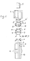
- Figure 1 shows the hose 5 starting from above and below the union nut 4 with an internal thread (not shown). Below this, the outer clamping body 8 is shown, which carries the lip 12 at the bottom, which penetrates into the tube material when screwed on.
- the cross section of the outer clamping body 8 is shown enlarged in FIG.
- This first clamping body 8 engages in the funnel 11 of the inner clamping body 7 a, the funnel angle ⁇ of the inner clamping body therefore corresponds to that ⁇ ' of the outer clamping body and is 85 - 95 °.
- the cutting lip 12 is on the Inside enclosed by the lip angle ⁇ , this is 55 - 65 °.
- the Lip 12 is bent off from the clamping body 8.
- the screw body 1 has a grommet 2, on the radially outward foot side a stop ring surface 3 connects.
- the hose 5 is on the spout 2 pushed and lies on the stop ring surface 3.
- the nozzle 6 follows, which preferably follows (in the illustration) extended at the top with an opening angle ⁇ of 25 - 35 °.
- the screw body 1 has an external thread 13 and a hexagon 14 for screwing with a tap. It can also have an internal thread and the like Hexagon.
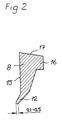
- Figure 2 shows the special shape of the outer (upper) clamping body 8 made of PEEK.
- This has a cylindrical surface 15 aligned parallel to the central axis of the screw connection, from which the lip 12 penetrating into the hose under its elastic deformation is bent. The corresponding angles are shown in Figure 1.
- the upper region of the clamping body advantageously has a bulge 16 and has a bevel 17, so that in this case too, the force introduction by the union nut is essentially linear and defined along the cylinder surface 15 with a vector.
- Figure 3 illustrates the assembly of the parts with the screw body 1.
- the hose 5 is pushed over the spout 2 to the stop surface 3 and secured by the screw connection with the union nut 4 and the clamping body 7, 8.
Abstract
Description
Die vorliegende Erfindung betrifft eine Schlauchverschraubung für insbesondere flexible Schläuche und starre Rohre. Die Verschraubung besteht dabei aus einem Verschraubungskörper mit einer an diesen angeformten Tülle, auf die der zu befestigende Schlauch geschoben wird. Der Schlauch ist dabei von einem Sicherungsring umfaßt, der von einer Überwurfmutter in einen der Tülle benachbarten konusförmigen Stutzen gedrückt wird und dadurch den Schlauch einklemmt, siehe z. B. DE 42 11 498 A1. Das hierzu verwendete Klemmelement kann dabei auch mehrteilig ausgebildet sein, so z. B. DE-OS 22 13 334.The present invention relates to a hose fitting for in particular flexible hoses and rigid pipes. The screw connection consists of one Screw body with a molded nozzle on which the fastening hose is pushed. The hose is from a circlip comprises of a union nut in one of the spout adjacent cone-shaped socket is pressed and thereby pinches the hose, see e.g. B. DE 42 11 498 A1. The clamping element used for this can also be formed in several parts, such. B. DE-OS 22 13 334.
Es hat sich herausgestellt, daß eine derartige Verschraubung flexible und starre (Kunststoff-)Schläuche bei Raumtemperatur sehr sicher hält, daß jedoch bei hohen Temperaturen bis 180°C und darüber eine Lockerung des Verbundes auftritt, so daß die Schläuche sich unbeabsichtigt aus der Verschraubung lösen können. Insbesondere ist dies nach einigen Temperaturlastwechseln der Fall.It has been found that such a screw connection is flexible and rigid (Plastic) hoses at room temperature holds very safely, but at high temperatures up to 180 ° C and above a loosening of the bond occurs so that the hoses unintentionally come loose from the screw connection can. This is especially the case after a few temperature load changes.
Die vorliegende Erfindung hat sich daher die Aufgabe gestellt, eine derartige Verschraubung dahingehend weiterzuentwickeln, daß sie auch bei höheren Temperaturen und auch nach einer Vielzahl von Temperaturwechseln den Schlauch sicher hält.The present invention has therefore set itself the task of such To further develop screw connections in such a way that they can also be used on higher ones Temperatures and also after a variety of temperature changes Hose holds securely.
Die Lösung dieser Aufgabe gelingt mit Hilfe einer die Merkmale des Hauptanspruchs aufweisenden Schlauchverschraubung. Vorteilhafte Ausgestaltungen finden sich in den Unteransprüchen.This problem is solved with the help of the features of the main claim having hose screw connection. Advantageous configurations can be found in the subclaims.
Durch die Teilung des Klemmkörpers wird erreicht, daß dessen Teile aus unterschiedlichen Materialien mit unterschiedlichen Festigkeitswerten ausgebildet werden können, d. h. die Aufgaben an die äußeren und inneren Klemmkörperbereiche können daher unterschiedlich sein.The division of the clamping body ensures that its parts from different Materials with different strength values are formed can be d. H. the tasks on the outer and inner sprag areas can therefore be different.
Weiterhin hat sich überraschenderweise herausgestellt, daß nur eine im wesentlichen lineare, ringförmige Anlagekante zwischen dem oberen Stutzenrand und der äußeren Mantelfläche des inneren Konus eine verbesserte Klemmwirkung gewährleistet. Dabei liegt die Klemmkante des Stutzens vorzugsweise etwa mittig zur inneren Anlagefläche des inneren Klemmkörpers am Schlauch. Wie herkömmlich ist der Stutzen dabei vorzugsweise ebenfalls konisch ausgebildet, wodurch die Krafteinleitung in den Verschraubungskörper verbessert wird.Furthermore, it has surprisingly been found that only one essentially linear, annular contact edge between the upper nozzle edge and the outer lateral surface of the inner cone an improved clamping effect guaranteed. The clamping edge of the nozzle is preferably approximately in the middle to the inner contact surface of the inner sprag on the hose. As usual the nozzle is preferably also conical, whereby the introduction of force into the screw body is improved.
Der zweite äußere Klemmkörperteil weist eine nach innen zum Schlauch gerichtete Lippe auf, die sich an der Trichterfläche des inneren Klemmkörpers abstützt, so daß diese beim Aufschrauben der Überwurfmutter in das Schlauchmaterial eindringt. An die Lippe schließt sich daher ebenfalls ein Freiraum an.The second outer clamping body part has an inward direction of the hose Lip, which is supported on the funnel surface of the inner clamping body, so that when screwing the union nut into the hose material penetrates. There is therefore also a free space at the lip.
Auf diese Weise ergibt sich sowohl eine Pressung des Schlauches durch den inneren Klemmkörper als auch ein Verkrallen mit den Befestigungsmitteln durch die Lippe des äußeren Klemmkörpers. Aus der Gesamtwirkung der linienförmigen Krafteinleitung in den inneren Klemmkörper zusammen und dem Verkrallen durch die Lippe ergibt sich ein schwingungs- und insbesondere temperaturunabhängiges Verhalten der Verschraubung.In this way, both the hose is pressed by the inner clamping body as well as clawing with the fasteners the lip of the outer sprag. From the overall effect of the linear Force transmission into the inner clamping body together and clawing through the lip is vibration and temperature independent Behavior of the screw connection.
Weiterhin hat sich herausgestellt, daß eine bestimmte unterschiedliche Werkstoffkombination für die inneren und äußeren Klemmkörper zusätzliche Festigkeitsvorteile bringt. Der äußere Klemmkörper besteht dabei aus Polyetheretherketon (PEEK) und der innere vorzugsweise aus Polytetrafluorethylen (PTFE).It has also been found that a certain different material combination additional strength advantages for the inner and outer clamp body brings. The outer clamping body consists of polyether ether ketone (PEEK) and the inner preferably made of polytetrafluoroethylene (PTFE).
Vorteilhaft ist weiterhin eine Auswahl und Kombination von Winkeln für den Stutzen, der insbesondere konisch ausgeführt ist und einen Öffnungswinkel α von etwa 25 - 35°, vorzugsweise von 30°, besitzt, wobei der innere Klemmkörper einen Mantelwinkel β von etwa 28 - 45°, vorzugsweise von 37°, aufweist.A selection and combination of angles for the is also advantageous Nozzle, which is in particular conical and an opening angle α of about 25-35 °, preferably 30 °, with the inner clamping body has a lateral angle β of approximately 28-45 °, preferably 37 °.
Der innere Mantelkörper besitzt einen oberen (äußeren) Trichter, in den der zweite - äußere - Klemmkörper eingefügt wird, über den bei Krafteinwirkung durch die Überwurfmutter dessen Lippe axial eingeschnürt wird. Dieser Winkel γ beträgt 85 bis 95°, vorzugsweise 90°. Ebenso schließt natürlich die Lippe einen äußeren Winkel von etwa 85 - 95°, vorzugsweise von 90°, ein, wobei der innere Schneidlippenwinkel δ etwa 55 - 65°, vorzugsweise 60°, beträgt. The inner jacket body has an upper (outer) funnel into which the second - outer - clamping body is inserted, through the force applied by the union nut whose lip is constricted axially. This angle is γ 85 to 95 °, preferably 90 °. Likewise, of course, the lip closes an outer one An angle of about 85-95 °, preferably 90 °, with the inner cutting lip angle δ is approximately 55-65 °, preferably 60 °.
Die Lippe selbst ist vorzugsweise vom Klemmkörper abgeknickt ausgebildet, wobei die Innenfläche zylindrisch ausgebildet ist, so daß beim Einpressen die Innenfläche auch plan an den Schlauch anlegbar ist. Hierdurch ist insbesondere die Eindringtiefe der Lippe in den Schlauch begrenzbar, um diesen vor Zerstörung zu schützen, so daß dieser gleichsam als Endausschlag für die Überwurfmutter dient.The lip itself is preferably bent off from the clamping body, wherein the inner surface is cylindrical, so that when pressed in The inner surface can also be placed flat on the hose. This is particularly the depth of penetration of the lip in the hose can be limited to prevent it from being destroyed to protect, so that this as it were as a final deflection for the cap nut serves.
Anhand der bieliegenden Figuren wird die vorliegende Erfindung näher erläutert.The present invention is explained in more detail with reference to the attached figures.
Dabei zeigen
-
Figur 1 - die Verschraubung in Explosionsdarstellung,
-
Figur 2 - den äußeren Klemmkörper und
-
Figur 3 - diese in zusammengebautem Zustand.
- Figure 1
- the screw connection in an exploded view,
- Figure 2
- the outer clamp body and
- Figure 3
- these in assembled condition.
Figur 1 zeigt von oben beginnend den Schlauch 5 und darunter die Überwurfmutter
4 mit Innengewinde (nicht dargestellt). Darunter ist der äußere Klemmkörper 8
gezeigt, der unten die Lippe 12 trägt, die beim Verschrauben in das Schlauchmaterial
eindringt. Figure 1 shows the
Der Querschnitt des äußeren Klemmkörpers 8 ist in Figur 2 vergrößert dargestellt.
Dieser erste Klemmkörper 8 greift in den Trichter 11 des inneren Klemmkörpers 7
ein, dem Trichterwinkel γ des inneren Klemmkörpers entspricht daher demjenigen γ'
des äußeren Klemmkörpers und beträgt 85 - 95°. Die Schneidlippe 12 wird auf der
Innenseite eingeschlossen durch den Lippenwinkel δ, dieser beträgt 55 - 65°. Die
Lippe 12 ist vom Klemmkörper 8 abgeknickt ausgebildet.The cross section of the
Der Verschraubungskörper 1 besitzt eine Tülle 2, an die radial nach außen fußseitig
eine Anschlagringfläche 3 anschließt. Der Schlauch 5 wird auf die Tülle 2
geschoben und liegt an der Anschlagringfläche 3 auf. An die Anschlagringfläche 3
schließt sich der Stutzen 6 an, der sich vorzugsweise (in der Darstellung) nach
oben mit einem Öffnungswinkel α von 25 - 35° erweitert. Der Verschraubungskörper
1 besitzt ein Außengewinde 13 sowie einen Sechskant 14 zur Verschraubung
mit einer Armatur. Er kann auch mit Innengewinde und entsprechendem
Sechskant versehen sein.The
Figur 2 zeigt die besondere Form des äußeren (oberen) Klemmkörpers 8 aus
PEEK. Dieser besitzt eine parallel zur Mittelachse der Verschraubung ausgerichtete
Zylinderfläche 15, von der die in den Schlauch unter dessen elastischer Verformung
eindringende Lippe 12 abgeknickt ist. Die entsprechenden Winkel sind in
Figur 1 angegeben. Der obere Bereich des Klemmkörpers weist vorteilhaft einen
Wulst 16 auf und besitzt eine Abschrägung 17, so daß auch in diesem Falle die
Krafteinleitung durch die Überwurfmutter im wesentlichen linienförmig und definiert
mit einem Vektor längs der Zylinderfläche 15 erfolgt. Figure 2 shows the special shape of the outer (upper)
Figur 3 veranschaulicht den Zusammenbau der Teile mit dem Verschraubungskörper
1. Der Schlauch 5 ist über die Tülle 2 bis an die Anschlagfläche 3 geschoben
und durch die Verschraubung mit Hilfe der Überwurfmutter 4 und der Klemmkörper
7, 8 gesichert. Figure 3 illustrates the assembly of the parts with the
Durch die schräg verlaufende äußere Mantelfläche 9 des inneren Klemmkörpers 7
mit der davon abweichenden Schräge des Stutzens 6 entsteht ein Freiraum 10,
d. h. die Oberkante des Stutzens 6 liegt linienförmig am Klemmkörper 7 an.
Ebenso ruht die Überwurfmutter 4 kreislinienförmig auf dem oberen Klemmkörper
8. Durch die Kombination der erfindungsgemäßen Merkmale entsteht eine
hochtemperaturfeste Verschraubung. Unter einem Druck von 6 bar entsteht auch
bei häufigem Abkühlen bei 180°C keine Undichtigkeit. Through the inclined
- 11
- VerschraubungskörperScrew body
- 22nd
- Tüllegrommet
- 33rd
- AnschlagringflächeStop ring surface
- 44th
- ÜberwurfmutterCap nut
- 55
- Schlauchtube
- 66
- StutzenSupport
- 77
- innerer Klemmkörperinner sprag
- 88th
- äußerer Klemmkörperouter sprag
- 99
- äußere Mantelflächeouter surface
- 1010th
- Freiraumfree space
- 1111
- Trichterfunnel
- 1212th
- Lippelip
- 1313
- AußengewindeExternal thread
- 1414
- SechskantHexagon
- 1515
- ZylinderflächeCylinder surface
- 1616
- Wulstbead
- 1717th
- Abschrägungbevel
- αα
- ÖffnungswinkelOpening angle
- ββ
- MantelwinkelJacket angle
- γγ
- TrichterwinkelFunnel angle
- δδ
- SchneidlippenwinkelCutting lip angle
Claims (7)
Applications Claiming Priority (2)
| Application Number | Priority Date | Filing Date | Title |
|---|---|---|---|
| DE19721179A DE19721179C1 (en) | 1997-05-21 | 1997-05-21 | Hose screw connection |
| DE19721179 | 1997-05-21 |
Publications (3)
| Publication Number | Publication Date |
|---|---|
| EP0879980A2 true EP0879980A2 (en) | 1998-11-25 |
| EP0879980A3 EP0879980A3 (en) | 2001-02-28 |
| EP0879980B1 EP0879980B1 (en) | 2003-10-15 |
Family
ID=7830040
Family Applications (1)
| Application Number | Title | Priority Date | Filing Date |
|---|---|---|---|
| EP98106918A Expired - Lifetime EP0879980B1 (en) | 1997-05-21 | 1998-04-16 | Screw coupling for hoses |
Country Status (6)
| Country | Link |
|---|---|
| EP (1) | EP0879980B1 (en) |
| AT (1) | ATE252209T1 (en) |
| DE (2) | DE19721179C1 (en) |
| DK (1) | DK0879980T3 (en) |
| ES (1) | ES2208994T3 (en) |
| PT (1) | PT879980E (en) |
Cited By (8)
| Publication number | Priority date | Publication date | Assignee | Title |
|---|---|---|---|---|
| DE102006062690A1 (en) | 2005-07-28 | 2008-07-03 | Hidde, Axel R., Dr. | Breathable hose/pipe joint for use as cable entry module in switch cabinet construction, has cylindrical hose/pipe jaw located in upper part of joint forming recess of hose/pipe, where jaw is provided with sealing/clamping element |
| EP2447586A1 (en) * | 2010-10-26 | 2012-05-02 | Michael Meier | Hose coupling |
| US10024468B2 (en) | 2014-05-09 | 2018-07-17 | Swagelok Company | Conduit fitting with components adapted for facilitating assembly |
| CN109296858A (en) * | 2018-11-23 | 2019-02-01 | 中国石油大学(华东) | A kind of ocean flexible pipe joint structure |
| US10215315B2 (en) | 2008-09-05 | 2019-02-26 | Parker-Hannifin Corporation | Tube compression fitting and flared fitting used with connection body and method of making same |
| DE102018205397A1 (en) | 2018-04-10 | 2019-10-10 | Wmf Group Gmbh | Clamping ring for hose connections, the clamping ring comprehensive clamping device for hose connections and the clamping device comprehensive hose connection |
| DE102009044807B4 (en) * | 2009-09-15 | 2019-12-24 | Continental Teves Ag & Co. Ohg | Clamping ring set |
| US10584814B2 (en) | 2016-03-23 | 2020-03-10 | Swagelok Company | Conduit fitting with stroke resisting features |
Families Citing this family (1)
| Publication number | Priority date | Publication date | Assignee | Title |
|---|---|---|---|---|
| CN111928045A (en) * | 2020-07-28 | 2020-11-13 | 泰州市光明电子材料有限公司 | Polytetrafluoroethylene pipe quick connector |
Citations (2)
| Publication number | Priority date | Publication date | Assignee | Title |
|---|---|---|---|---|
| DE2213334A1 (en) | 1971-04-15 | 1972-11-02 | Crawford Fitting Co., Solon, Ohio (V.StA.) | Pipe connector |
| DE4211498A1 (en) | 1992-04-06 | 1993-10-07 | Em Technik Gmbh Armaturenbau | Pipe screwing arrangement for relatively rigid hoses - comprises screwing body with insert aperture for hose and sealing bush which pushes onto hose |
Family Cites Families (8)
| Publication number | Priority date | Publication date | Assignee | Title |
|---|---|---|---|---|
| DE956554C (en) * | 1954-04-30 | 1957-01-17 | Hans Kreidel Jun | Adaptation cone for cutting ring pipe connections |
| US3075793A (en) * | 1959-06-03 | 1963-01-29 | Crawford Fitting Co | Packed wedge type coupling having positioning means |
| US3103373A (en) * | 1961-06-29 | 1963-09-10 | Crawford Fitting Co | Controlled phase sequential gripping device |
| GB1146673A (en) * | 1965-08-13 | 1969-03-26 | E E Jeavons & Co Ltd | Improvements in or relating to pipe joints |
| DE1625961C3 (en) * | 1967-10-31 | 1973-11-08 | Einar Bjoern Oslo Christensen | Coupling for connecting a rigid or flexible pipe to a connection piece |
| FR2468826A1 (en) * | 1979-10-31 | 1981-05-08 | Capri Codec Sa | Pipe couplings with conic seals backed by an annular spring - to compensate for elastic fatigue by thermal cycling |
| US4304422A (en) * | 1980-02-19 | 1981-12-08 | Gould Inc. | Tube coupling with frangible sleeve |
| DE8031377U1 (en) * | 1980-11-25 | 1981-04-02 | Em-Technik Gmbh Armaturenbau, 6701 Maxdorf | HOSE CONNECTOR |
-
1997
- 1997-05-21 DE DE19721179A patent/DE19721179C1/en not_active Expired - Lifetime
-
1998
- 1998-04-16 EP EP98106918A patent/EP0879980B1/en not_active Expired - Lifetime
- 1998-04-16 AT AT98106918T patent/ATE252209T1/en active
- 1998-04-16 PT PT98106918T patent/PT879980E/en unknown
- 1998-04-16 DK DK98106918T patent/DK0879980T3/en active
- 1998-04-16 DE DE59809898T patent/DE59809898D1/en not_active Expired - Lifetime
- 1998-04-16 ES ES98106918T patent/ES2208994T3/en not_active Expired - Lifetime
Patent Citations (2)
| Publication number | Priority date | Publication date | Assignee | Title |
|---|---|---|---|---|
| DE2213334A1 (en) | 1971-04-15 | 1972-11-02 | Crawford Fitting Co., Solon, Ohio (V.StA.) | Pipe connector |
| DE4211498A1 (en) | 1992-04-06 | 1993-10-07 | Em Technik Gmbh Armaturenbau | Pipe screwing arrangement for relatively rigid hoses - comprises screwing body with insert aperture for hose and sealing bush which pushes onto hose |
Cited By (11)
| Publication number | Priority date | Publication date | Assignee | Title |
|---|---|---|---|---|
| DE102006062690A1 (en) | 2005-07-28 | 2008-07-03 | Hidde, Axel R., Dr. | Breathable hose/pipe joint for use as cable entry module in switch cabinet construction, has cylindrical hose/pipe jaw located in upper part of joint forming recess of hose/pipe, where jaw is provided with sealing/clamping element |
| DE102006062690B4 (en) * | 2005-07-28 | 2015-10-29 | Axel R. Hidde | Hose / pipe fitting with diaphragm valve |
| US10215315B2 (en) | 2008-09-05 | 2019-02-26 | Parker-Hannifin Corporation | Tube compression fitting and flared fitting used with connection body and method of making same |
| DE102009044807B4 (en) * | 2009-09-15 | 2019-12-24 | Continental Teves Ag & Co. Ohg | Clamping ring set |
| EP2447586A1 (en) * | 2010-10-26 | 2012-05-02 | Michael Meier | Hose coupling |
| US10024468B2 (en) | 2014-05-09 | 2018-07-17 | Swagelok Company | Conduit fitting with components adapted for facilitating assembly |
| US11079046B2 (en) | 2014-05-09 | 2021-08-03 | Swagelok Company | Conduit fitting with components adapted for facilitating assembly |
| US10584814B2 (en) | 2016-03-23 | 2020-03-10 | Swagelok Company | Conduit fitting with stroke resisting features |
| US11009158B2 (en) | 2016-03-23 | 2021-05-18 | Swagelok Company | Conduit fitting with stroke resisting features |
| DE102018205397A1 (en) | 2018-04-10 | 2019-10-10 | Wmf Group Gmbh | Clamping ring for hose connections, the clamping ring comprehensive clamping device for hose connections and the clamping device comprehensive hose connection |
| CN109296858A (en) * | 2018-11-23 | 2019-02-01 | 中国石油大学(华东) | A kind of ocean flexible pipe joint structure |
Also Published As
| Publication number | Publication date |
|---|---|
| PT879980E (en) | 2004-03-31 |
| DE59809898D1 (en) | 2003-11-20 |
| DE19721179C1 (en) | 1998-10-08 |
| EP0879980A3 (en) | 2001-02-28 |
| DK0879980T3 (en) | 2004-02-16 |
| EP0879980B1 (en) | 2003-10-15 |
| ATE252209T1 (en) | 2003-11-15 |
| ES2208994T3 (en) | 2004-06-16 |
Similar Documents
| Publication | Publication Date | Title |
|---|---|---|
| EP0728979B1 (en) | Sealing connection between a plastic pipe and a connecting piece made of metal | |
| DE2241521C3 (en) | Ball valve | |
| EP0099529A1 (en) | Socket pipe section | |
| DE2521930C2 (en) | Pipe connector | |
| EP0592823A1 (en) | Releasable plug coupling for plastic pipes | |
| EP1030097B1 (en) | Connecting device having an armature body rotatably fastened | |
| EP0565820B1 (en) | Threaded joint | |
| EP0879980B1 (en) | Screw coupling for hoses | |
| DE1297418B (en) | Pipe connection | |
| DE10207104B4 (en) | Truncated cone-shaped sealing connection piece | |
| EP1881251A2 (en) | Gasket and connecting device for a socket joint | |
| DE2758592A1 (en) | JOINT FORMATION FOR FASTENING A PIPE IN THE OPENING OF A WALL | |
| DE10347927B4 (en) | Method and device for producing a pipe press connection on a plug connection | |
| DE102006015918B4 (en) | valves | |
| WO1998006967A1 (en) | Telescopic tube, in particular for sprinkler systems | |
| DE4211498A1 (en) | Pipe screwing arrangement for relatively rigid hoses - comprises screwing body with insert aperture for hose and sealing bush which pushes onto hose | |
| EP1006307B1 (en) | Pin-and-socket coupling | |
| EP0461308B1 (en) | Transition piece for connecting plastic pipes with a metallic reinforcement, in particular in the sanitary and heating fields | |
| DE2428589A1 (en) | SCREW CONNECTION | |
| DE3045533C2 (en) | Hose socket for pressure hoses | |
| DE3208295A1 (en) | Screw-cap cutting closure | |
| DE4025878C2 (en) | Connection device for pipes | |
| DE7819692U1 (en) | PIPE SOCKET | |
| DE19730367B4 (en) | Elastomer sleeve for the sealing connection of two pipe ends | |
| EP1416211B1 (en) | Tube coupling |
Legal Events
| Date | Code | Title | Description |
|---|---|---|---|
| PUAI | Public reference made under article 153(3) epc to a published international application that has entered the european phase |
Free format text: ORIGINAL CODE: 0009012 |
|
| AK | Designated contracting states |
Kind code of ref document: A2 Designated state(s): AT BE CH CY DE DK ES FI FR GB GR IE IT LI LU MC NL PT SE |
|
| AX | Request for extension of the european patent |
Free format text: AL;LT;LV;MK;RO;SI |
|
| PUAL | Search report despatched |
Free format text: ORIGINAL CODE: 0009013 |
|
| AK | Designated contracting states |
Kind code of ref document: A3 Designated state(s): AT BE CH CY DE DK ES FI FR GB GR IE IT LI LU MC NL PT SE |
|
| AX | Request for extension of the european patent |
Free format text: AL;LT;LV;MK;RO;SI |
|
| RIC1 | Information provided on ipc code assigned before grant |
Free format text: 7F 16L 19/10 A, 7F 16L 33/22 B |
|
| 17P | Request for examination filed |
Effective date: 20010228 |
|
| AKX | Designation fees paid |
Free format text: AT BE CH CY DE DK ES FI FR GB GR IE IT LI LU MC NL PT SE |
|
| GRAH | Despatch of communication of intention to grant a patent |
Free format text: ORIGINAL CODE: EPIDOS IGRA |
|
| GRAS | Grant fee paid |
Free format text: ORIGINAL CODE: EPIDOSNIGR3 |
|
| GRAA | (expected) grant |
Free format text: ORIGINAL CODE: 0009210 |
|
| AK | Designated contracting states |
Kind code of ref document: B1 Designated state(s): AT BE CH CY DE DK ES FI FR GB GR IE IT LI LU MC NL PT SE |
|
| REG | Reference to a national code |
Ref country code: GB Ref legal event code: FG4D Free format text: NOT ENGLISH Ref country code: CH Ref legal event code: EP |
|
| REG | Reference to a national code |
Ref country code: IE Ref legal event code: FG4D Free format text: GERMAN |
|
| REG | Reference to a national code |
Ref country code: CH Ref legal event code: NV Representative=s name: PATENTANWAELTE FELDMANN & PARTNER AG |
|
| REF | Corresponds to: |
Ref document number: 59809898 Country of ref document: DE Date of ref document: 20031120 Kind code of ref document: P |
|
| REG | Reference to a national code |
Ref country code: SE Ref legal event code: TRGR |
|
| GBT | Gb: translation of ep patent filed (gb section 77(6)(a)/1977) |
Effective date: 20031211 |
|
| REG | Reference to a national code |
Ref country code: DK Ref legal event code: T3 |
|
| REG | Reference to a national code |
Ref country code: GR Ref legal event code: EP Ref document number: 20040400623 Country of ref document: GR |
|
| REG | Reference to a national code |
Ref country code: PT Ref legal event code: SC4A Free format text: AVAILABILITY OF NATIONAL TRANSLATION Effective date: 20040114 |
|
| REG | Reference to a national code |
Ref country code: PT Ref legal event code: PD4A Free format text: EM-TECHNIK GMBH ARMATURENBAU DE Effective date: 20040406 |
|
| REG | Reference to a national code |
Ref country code: ES Ref legal event code: FG2A Ref document number: 2208994 Country of ref document: ES Kind code of ref document: T3 |
|
| ET | Fr: translation filed | ||
| PLBE | No opposition filed within time limit |
Free format text: ORIGINAL CODE: 0009261 |
|
| STAA | Information on the status of an ep patent application or granted ep patent |
Free format text: STATUS: NO OPPOSITION FILED WITHIN TIME LIMIT |
|
| 26N | No opposition filed |
Effective date: 20040716 |
|
| REG | Reference to a national code |
Ref country code: CH Ref legal event code: PFA Owner name: EM-TECHNIK GMBH Free format text: EM-TECHNIK GMBH#ARMATURENBAU INDUSTRIESTRASSE 2#D-67133 MAXDORF (DE) -TRANSFER TO- EM-TECHNIK GMBH#ARMATURENBAU INDUSTRIESTRASSE 2#D-67133 MAXDORF (DE) |
|
| REG | Reference to a national code |
Ref country code: FR Ref legal event code: PLFP Year of fee payment: 19 |
|
| REG | Reference to a national code |
Ref country code: FR Ref legal event code: PLFP Year of fee payment: 20 |
|
| PGFP | Annual fee paid to national office [announced via postgrant information from national office to epo] |
Ref country code: NL Payment date: 20170424 Year of fee payment: 20 |
|
| PGFP | Annual fee paid to national office [announced via postgrant information from national office to epo] |
Ref country code: GR Payment date: 20170425 Year of fee payment: 20 Ref country code: GB Payment date: 20170425 Year of fee payment: 20 Ref country code: DK Payment date: 20170424 Year of fee payment: 20 Ref country code: FR Payment date: 20170424 Year of fee payment: 20 Ref country code: CY Payment date: 20170405 Year of fee payment: 20 Ref country code: MC Payment date: 20170421 Year of fee payment: 20 Ref country code: IE Payment date: 20170424 Year of fee payment: 20 Ref country code: DE Payment date: 20170425 Year of fee payment: 20 Ref country code: CH Payment date: 20170425 Year of fee payment: 20 |
|
| PGFP | Annual fee paid to national office [announced via postgrant information from national office to epo] |
Ref country code: ES Payment date: 20170503 Year of fee payment: 20 Ref country code: SE Payment date: 20170425 Year of fee payment: 20 Ref country code: AT Payment date: 20170420 Year of fee payment: 20 Ref country code: PT Payment date: 20170407 Year of fee payment: 20 Ref country code: BE Payment date: 20170424 Year of fee payment: 20 Ref country code: IT Payment date: 20170420 Year of fee payment: 20 Ref country code: LU Payment date: 20170424 Year of fee payment: 20 Ref country code: FI Payment date: 20170420 Year of fee payment: 20 |
|
| REG | Reference to a national code |
Ref country code: DE Ref legal event code: R071 Ref document number: 59809898 Country of ref document: DE |
|
| REG | Reference to a national code |
Ref country code: NL Ref legal event code: MK Effective date: 20180415 |
|
| REG | Reference to a national code |
Ref country code: DK Ref legal event code: EUP Effective date: 20180416 |
|
| REG | Reference to a national code |
Ref country code: CH Ref legal event code: PL |
|
| REG | Reference to a national code |
Ref country code: GB Ref legal event code: PE20 Expiry date: 20180415 |
|
| REG | Reference to a national code |
Ref country code: SE Ref legal event code: EUG |
|
| REG | Reference to a national code |
Ref country code: IE Ref legal event code: MK9A |
|
| REG | Reference to a national code |
Ref country code: AT Ref legal event code: MK07 Ref document number: 252209 Country of ref document: AT Kind code of ref document: T Effective date: 20180416 Ref country code: BE Ref legal event code: MK Effective date: 20180416 |
|
| PG25 | Lapsed in a contracting state [announced via postgrant information from national office to epo] |
Ref country code: GB Free format text: LAPSE BECAUSE OF EXPIRATION OF PROTECTION Effective date: 20180415 Ref country code: IE Free format text: LAPSE BECAUSE OF EXPIRATION OF PROTECTION Effective date: 20180416 Ref country code: PT Free format text: LAPSE BECAUSE OF EXPIRATION OF PROTECTION Effective date: 20180426 |
|
| REG | Reference to a national code |
Ref country code: ES Ref legal event code: FD2A Effective date: 20200902 |
|
| PG25 | Lapsed in a contracting state [announced via postgrant information from national office to epo] |
Ref country code: ES Free format text: LAPSE BECAUSE OF EXPIRATION OF PROTECTION Effective date: 20180417 |