EP0879919A2 - Vorrichtung zur Reinigung von Tunnelwänden und/oder Tunneldecken - Google Patents
Vorrichtung zur Reinigung von Tunnelwänden und/oder Tunneldecken Download PDFInfo
- Publication number
- EP0879919A2 EP0879919A2 EP98109347A EP98109347A EP0879919A2 EP 0879919 A2 EP0879919 A2 EP 0879919A2 EP 98109347 A EP98109347 A EP 98109347A EP 98109347 A EP98109347 A EP 98109347A EP 0879919 A2 EP0879919 A2 EP 0879919A2
- Authority
- EP
- European Patent Office
- Prior art keywords
- tunnel
- hood
- nozzle
- suction
- suction hood
- Prior art date
- Legal status (The legal status is an assumption and is not a legal conclusion. Google has not performed a legal analysis and makes no representation as to the accuracy of the status listed.)
- Granted
Links
Images


Classifications
-
- E—FIXED CONSTRUCTIONS
- E01—CONSTRUCTION OF ROADS, RAILWAYS, OR BRIDGES
- E01H—STREET CLEANING; CLEANING OF PERMANENT WAYS; CLEANING BEACHES; DISPERSING OR PREVENTING FOG IN GENERAL CLEANING STREET OR RAILWAY FURNITURE OR TUNNEL WALLS
- E01H1/00—Removing undesirable matter from roads or like surfaces, with or without moistening of the surface
- E01H1/005—Mobile installations, particularly for upkeeping in situ road or railway furniture, for instance road barricades, traffic signs; Mobile installations particularly for upkeeping tunnel walls
Definitions
- Tunnel walls and / or tunnel ceilings are subject to the Vehicles passing through a tunnel of heavy pollution, so that cleaning is required at regular intervals is. If the tunnel walls are smooth with tiles or the like Materials are formed, as is the case with car tunnels is usual, cleaning with roller broom systems under Add water. A corresponding tunnel cleaning machine is by German interpretation 16 58 405 known.
- washing liquid does indeed work with the mechanical one Assistance by cleaning the brush Tunnel walls, nevertheless stick to the well-known tunnel washing vehicle serious disadvantages.
- the use of washing liquid and water leads to unwanted soaking the traffic area or the ground, and it must also be taken into account that in addition to the high water consumption with the Dirty water gets into the sewage system. Furthermore it is particularly disadvantageous when using water, that through the use of water there is a risk of cable fires with the existing electrical lines in the tunnel or also given with the existing electrical control boxes is.
- the invention has for its object a device to create tunnel walls and ceilings, which with simple means wet the tunnel floor as well as pollution of the sewage systems with dirty Water avoids, and which also the danger of cable fires and short circuits eliminated.
- the invention is based on the basic idea that Cleaning tunnel walls by adding water to one Compressed air flow to produce an aerosol that works with pressure is sprayed against the tunnel walls and loosens the dirt and in a dusty atmosphere in the form of an air-dirt-water mixture transferred. Compared to known solutions this significantly reduces water consumption because only relatively little water added to the compressed air flow needs to be.
- Several are used to generate the aerosol blow nozzles each arranged on the circumference of a nozzle hood an injector.
- A is used to extract the dust-containing atmosphere suction hood arranged at a distance from the nozzle hood is used.
- An important aspect of the invention is that a suction chamber is formed between the nozzle hood and the suction hood is, and this ensures that the dusty Atmosphere with the loosened dirt does not remain, but can be sucked into a dirt container.
- Both the nozzle hood and the suction hood extend not all the way to the tunnel wall, but end at a distance from the tunnel wall, so that the aforementioned from the Parts of the tunnel wall do not touch the two hoods be, but on the other hand with the water Compressed air flow for cleaning. Because only comparatively little water is used and also the generated dust-containing atmosphere is extracted, the Use of water no problems, for example cable fires or others possible through exposure to water Consequential damage is avoided.
- the sewage systems are not burdened at all by cleaning the tunnel walls, because the dusty atmosphere in a closed Dirt container is collected. For this reason, it is omitted advantageously also a wetting of the tunnel floor.
- the inventive device for performing the method includes the nozzle hood already mentioned, along the tunnel is movable and at a distance from the tunnel wall or extends from the tunnel ceiling. On the circumference of the nozzle hood are several distributed with an injector Blow nozzles arranged, which are directed to the tunnel wall.
- a compressed air / water mixture is directed towards the tunnel wall which forms an aerosol and which on the Debris and dirt and stuck deposits Dust dissolves and creates a dusty atmosphere.
- the tunnel is facing forward is largely sealed by the nozzle hood.
- Seen in the direction of travel behind the nozzle hood includes the invention Device also arranged to be movable Suction hood with essentially the same dimensions and same shape as the nozzle hood.
- the suction hood has at least a suction arrangement for extracting the dusty atmosphere, which is in the space between the nozzle hood and the suction hood is located. It is still an advantage that the tunnel through the suction hood largely in the direction of travel is sealed to the rear so that between the Nozzle hood on the one hand and the suction hood on the other Suction chamber is formed.
- the nozzle hood comprises adjustable segments, each with a variety of blowing nozzles are arranged, and the radially towards the tunnel wall and adjustable in the opposite direction are.
- the size or the outer Dimensions of the suction hood are changeable.
- the size or the outer Dimensions of the suction hood are changeable.
- Another expedient embodiment of the invention provides before that the outer edge of both the nozzle hood and the Suction hood is provided with an elastic hood end.
- This elastic hood closure extends further towards the tunnel wall as the nozzle hood and the Suction hood itself.
- the elastic hood ends definitely with those that protrude from the tunnel wall Parts and railway equipment in contact come.
- this is not annoying because of the elastic Design of the hood ends z. B. in the form of Rubber will not damage the railway equipment.
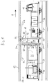
- FIG. 1 shows a tunnel 10 as a railway tunnel with a tunnel wall 12.
- a towing vehicle 16 which is coupled to a wagon 14.
- nozzle hood 18 At the rear end of the towing vehicle 16 there is a nozzle hood 18, and further are on the towing vehicle 16 Water tank 32 and a compressor 34 for the operation of the nozzle hood 18 provided.
- a suction hood 20 is arranged at the front end of the wagon 14, which comprises a suction funnel 22. Also located a dirt container 26 and one on the wagon 14 Fan 28 with an exhaust duct and a motor 30 for the Operation of the suction hood 20.
- the outer dimensions of the nozzle hood 18 are less than the inner cross section of the tunnel 10 in such a way that any existing and projecting from the tunnel wall 12 inwards Parts of the nozzle hood 18 while driving through the Tunnels are not touched.
- the nozzle hood 18 has one elastic hood closure 56, through which the outer dimensions the nozzle hood 18 can be enlarged, but the is always at a distance from the tunnel wall 12 and so on leaves a gap. This gap is important thus an air flow 52 through it into a suction chamber 24 can get through the space between the nozzle hood 18 and the suction hood 20 is formed.
- the mentioned from the Tunnel wall 12 outstanding parts are covered by the hood 56 not damaged because the hood end 56 is elastic is trained and can avoid these parts.
- the suction hood 20 has approximately the same outer dimensions like the nozzle hood 18 and is also with an elastic Hood cover 54 provided the same function how the elastic hood closure 56 of the nozzle hood meets.
- the elastic hood closure 54 also allows one Gap free, through which an air flow 52 into the suction chamber 24 can reach.
- the tunnel 10 or the corresponding tunnel cross section is through the nozzle hood 18 and the suction hood 20 mostly, but not because of the column mentioned completely sealed. However, the seal is sufficient enough that between the nozzle hood 18 and the Suction hood 20 can form the aforementioned suction chamber 24.
- FIG. 2 shows an example of a cross section of a tunnel 10, which is formed by a tunnel tube 36.
- Tunnel lighting 38 and various supply lines are such 40 as required railway facilities intended.
- These parts face the tunnel wall 12 outstanding parts and are allowed to drive with the towing vehicle 16 are not damaged. For this reason a clearance profile is shown in Fig. 2, which the Delimits the area of the tunnel cross-section that is absolutely free is to be kept in order to damage the railway equipment to avoid.
- FIG. 3 shows adjustable segments 48 of the nozzle hood 18 shown, together with an adjustable bulkhead 46. Sensor-controlled pneumatic cylinders are used for the adjustment 50 provided.
- the dashed line 44 indicates the vehicle body of the towing vehicle again.
- Fig. 4 the segments 48 and the bulkhead 46 in the extended Position.
- the pneumatic cylinder 50 By actuating the pneumatic cylinder 50 has the outer circumference of the nozzle hood 18 is enlarged.
- the individual adjustable segments 48 can if necessary overlap and in different parallel planes are located.
- blowing nozzles 58 which are provided on the nozzle hood 18 are and expediently on the adjustable Segments 48 are located.
- the blowing nozzles 58 are on the outer edge the adjustable segments 48 arranged so that they are in are close to the tunnel wall 12.
- FIGS A plurality of blowing nozzles 58 are shown in FIGS a common first ring line 60 and a second Ring line 62 fed; 7 is a third one Ring line 64 and a fourth ring line 66 shown.
- hose connections 70 are provided around connect to adjacent segments 48.
- each blowing nozzle 58 produces each blowing nozzle 58 a compressed air water mixture or a compressed air water jet 68, which is directed to the tunnel wall 12.
- a compressed air water jet 68 becomes the dirt from the tunnel wall 12 solved and transferred into a dusty atmosphere.
- the dusty atmosphere is an air-dirt-water mixture 72 (see FIG. 1), the water content is comparatively small.
- the suction funnel 22 is also the largest Part of the water used for cleaning is also collected. The bottom of the tunnel 10 is therefore subject to practical conditions no drenching.
- the different Ring lines 60 - 66 operated pulsating, so that from only a part of all of the blowing nozzles 58 involved is and the compressed air / water mixture 68 sprays.
- the blow nozzles in this way work pulsating that only a third of the blow nozzles 68 is in use at the same time.
Abstract
Description
- Fig. 1
- eine schematische Seitenansicht einer auf Schienenfahrzeugen angeordneten Vorrichtung in einem Tunnel,
- Fig. 2
- eine Querschnittansicht eines Tunnels ohne die erfindungsgemäße Vorrichtung,
- Fig. 3
- eine Querschnittansicht eines Tunnels mit einer erfindungsgemäßen Vorrichtung mit der Ansicht einer Düsenhaube mit verstellbaren Segmenten,
- Fig. 4
- eine Ansicht gemäß Fig. 3, wobei die verstellbaren Segmente der Düsenhaube ausgefahren sind,
- Fig. 5u.6
- jeweils eine Teildarstellung von Blasdüsen in einer Draufsicht auf die Düsenhaube, und
- Fig. 7
- einen Längsschnitt einer Teildarstellung von Blasdüsen.
Claims (10)
- Vorrichtung zur Reinigung von Tunnelwänden und/oder von Tunneldecken von staubhaltigen festsitzenden Ablagerungen und von Schmutz, gekennzeichnet durch folgende Merkmale:eine längs des Tunnels (10) in eine Fahrtrichtung (A) verfahrbare Düsenhaube (18), die sich im Abstand von der Tunnelwand (12) bzw. der Tunneldecke (15) erstreckt, und durch die der Tunnel (10) überwiegend abgedichtet wird,auf dem im Abstand von der Tunnelwand (12) bzw. der Tunneldecke verlaufenden Umfang der Düsenhaube (18) sind mit einem Injektor versehene Blasdüsen (58) verteilt angeordnet,aus den Blasdüsen (58) tritt ein auf die Tunnelwand (12) bzw. auf die Tunneldecke gerichtetes Druckluftwassergemisch (68) aus, welches den auf der Tunnelwand (12) bzw. auf der Tunneldecke befindlichen Schmutz und Ablagerungen löst und eine staubhaltige Atmosphäre erzeugt,eine in Fahrtrichtung (A) gesehen hinter der Düsenhaube (18) im Abstand davon in gleicher Fahrtrichtung verfahrbar angeordnete Saughaube (20) mit im wesentlichen gleichen äußeren Abmessungen und gleicher Form wie die Düsenhaube (18),durch die Saughaube (20) ist der Tunnel (10) überwiegend abgedichtet,die Saughaube (20) besitzt mindestens eine Sauganordnung (22) zum Absaugen der staubhaltigen Atmosphäre, die sich in dem Raum (24) zwischen der Düsenhaube (18) und der Saughaube (20) befindet.
- Vorrichtung nach Anspruch 1, dadurch gekennzeichnet , daß die Düsenhaube (18) verstellbare Segmente (48) umfaßt, an denen jeweils eine Vielzahl von Blasdüsen (58) angeordnet sind, und die radial in Richtung auf die Tunnelwand (12) sowie in entgegengesetzte Richtung verstellbar sind.
- Vorrichtung nach Anspruch 1 und/oder 2, dadurch gekennzeichnet , daß mehrere Blasdüsen (58) von einer gemeinsamen Ringleitung (60 - 66) gespeist sind.
- Vorrichtung nach Anspruch 3, dadurch gekennzeichnet , daß mehrere Ringleitungen (60 - 66) mit jeweils eigenen Blasdüsen (58) vorgesehen sind.
- Vorrichtung nach Anspruch 4, dadurch gekennzeichnet , daß die Ringleitungen (60 - 66) pulsierend betrieben sind, derart, daß von allen Blasdüsen (58) jeweils nur ein Teil gleichzeitig ein Druckluftwassergemisch (68) versprüht.
- Vorrichtung nach Anspruch 5, dadurch gekennzeichnet , daß die Ringleitungen (60 - 66) pulsierend betrieben sind, derart, daß von allen Blasdüsen (58) jeweils nur ein Drittel gleichzeitig ein Druckluftwassergemisch (68) versprüht.
- Vorrichtung nach einem der vorhergehenden Ansprüche 1 - 6, dadurch gekennzeichnet , daß die Größe bzw. die äußeren Abmessungen der Saughaube (20) veränderbar sind.
- Vorrichtung nach einem der vorhergehenden Ansprüche 1 - 7, dadurch gekennzeichnet , daß der äußere Rand sowohl der Düsenhaube (18) als auch der Saughaube (20) mit einem elastischen Haubenabschluß (54; 56) versehen sind.
- Vorrichtung nach einem der vorhergehenden Ansprüche 1 - 8, dadurch gekennzeichnet , daß die Düsenhaube (18) am hinteren Ende eines Zugfahrzeuges (16) und die Saughaube (20) am vorderen Ende eines mit dem Zugfahrzeug (16) gekoppelten Waggons (14) angeordnet sind.
- Vorrichtung nach Anspruch 9, dadurch gekennzeichnet , daß ein für den Betrieb der Düsenhaube (18) vorgesehener Wassertank (32) und ein Kompressor (34) auf dem Zugfahrzeug (16) und ein für den Betrieb der Saughaube (20) vorgesehener Ventilator (28) sowie ein Schmutzbehälter (26) auf dem Waggon (14) vorgesehen sind.
Applications Claiming Priority (2)
| Application Number | Priority Date | Filing Date | Title |
|---|---|---|---|
| DE19721414 | 1997-05-22 | ||
| DE19721414 | 1997-05-22 |
Publications (3)
| Publication Number | Publication Date |
|---|---|
| EP0879919A2 true EP0879919A2 (de) | 1998-11-25 |
| EP0879919A3 EP0879919A3 (de) | 1999-12-01 |
| EP0879919B1 EP0879919B1 (de) | 2003-08-27 |
Family
ID=7830177
Family Applications (1)
| Application Number | Title | Priority Date | Filing Date |
|---|---|---|---|
| EP98109347A Expired - Lifetime EP0879919B1 (de) | 1997-05-22 | 1998-05-22 | Vorrichtung zur Reinigung von Tunnelwänden und/oder Tunneldecken |
Country Status (4)
| Country | Link |
|---|---|
| EP (1) | EP0879919B1 (de) |
| AT (1) | ATE248258T1 (de) |
| DE (1) | DE59809374D1 (de) |
| ES (1) | ES2206790T3 (de) |
Cited By (3)
| Publication number | Priority date | Publication date | Assignee | Title |
|---|---|---|---|---|
| WO2010075828A1 (de) * | 2008-12-30 | 2010-07-08 | Bes' T Global Engineering Ltd. | Verfahren und vorrichtung zur reinigung des gleisoberbaus sowie von tunnelwänden |
| CN106836099A (zh) * | 2016-12-27 | 2017-06-13 | 苏州大方特种车股份有限公司 | 隧道清洁车 |
| CN109423971A (zh) * | 2017-08-24 | 2019-03-05 | 中铁华铁工程设计集团有限公司 | 平面射流式地铁隧道吹扫设备 |
Families Citing this family (1)
| Publication number | Priority date | Publication date | Assignee | Title |
|---|---|---|---|---|
| DE102019100301A1 (de) | 2019-01-08 | 2020-07-09 | Cft Gmbh Compact Filter Technic | Tunnelreinigungszug |
Citations (2)
| Publication number | Priority date | Publication date | Assignee | Title |
|---|---|---|---|---|
| DE1658405A1 (de) | 1966-04-12 | 1970-11-05 | Materiel De Voirie | Selbstfahrende Einrichtung zum Reinigen von Tunnelwaenden |
| DE2658420A1 (de) | 1976-01-14 | 1977-07-21 | Zellinger Gmbh | Tunnelwaschfahrzeug |
Family Cites Families (1)
| Publication number | Priority date | Publication date | Assignee | Title |
|---|---|---|---|---|
| GB186970A (de) * | 1900-01-01 |
-
1998
- 1998-05-22 AT AT98109347T patent/ATE248258T1/de not_active IP Right Cessation
- 1998-05-22 DE DE59809374T patent/DE59809374D1/de not_active Expired - Fee Related
- 1998-05-22 EP EP98109347A patent/EP0879919B1/de not_active Expired - Lifetime
- 1998-05-22 ES ES98109347T patent/ES2206790T3/es not_active Expired - Lifetime
Patent Citations (2)
| Publication number | Priority date | Publication date | Assignee | Title |
|---|---|---|---|---|
| DE1658405A1 (de) | 1966-04-12 | 1970-11-05 | Materiel De Voirie | Selbstfahrende Einrichtung zum Reinigen von Tunnelwaenden |
| DE2658420A1 (de) | 1976-01-14 | 1977-07-21 | Zellinger Gmbh | Tunnelwaschfahrzeug |
Cited By (5)
| Publication number | Priority date | Publication date | Assignee | Title |
|---|---|---|---|---|
| WO2010075828A1 (de) * | 2008-12-30 | 2010-07-08 | Bes' T Global Engineering Ltd. | Verfahren und vorrichtung zur reinigung des gleisoberbaus sowie von tunnelwänden |
| EP2305892A2 (de) * | 2008-12-30 | 2011-04-06 | BES't Global Engineering Ltd. | Verfahren und Vorrichtung zur Reinigung des Gleisoberbaus sowie von Tunnelwänden |
| EP2305892A3 (de) * | 2008-12-30 | 2012-10-31 | Rodinia Technologies Ltd. | Verfahren und Vorrichtung zur Reinigung des Gleisoberbaus sowie von Tunnelwänden |
| CN106836099A (zh) * | 2016-12-27 | 2017-06-13 | 苏州大方特种车股份有限公司 | 隧道清洁车 |
| CN109423971A (zh) * | 2017-08-24 | 2019-03-05 | 中铁华铁工程设计集团有限公司 | 平面射流式地铁隧道吹扫设备 |
Also Published As
| Publication number | Publication date |
|---|---|
| DE59809374D1 (de) | 2003-10-02 |
| EP0879919B1 (de) | 2003-08-27 |
| ATE248258T1 (de) | 2003-09-15 |
| ES2206790T3 (es) | 2004-05-16 |
| EP0879919A3 (de) | 1999-12-01 |
Similar Documents
| Publication | Publication Date | Title |
|---|---|---|
| EP0337048B1 (de) | Gleisfahrbare Maschine zum Reinigen eines Gleisoberbaues mit Saug-Einrichtung | |
| EP3418450B1 (de) | Tunnelreinigungsvorrichtung | |
| EP3365216B1 (de) | Pneumatische trittplattenreinigung | |
| DE1954950U (de) | Als fahrzeug ausgebildete vorrichtung zur reinigung von strassen od. dgl. | |
| EP0637531B1 (de) | Vorrichtung zum Reinigen eines Zweirades, insbesondere eines Fahrrades | |
| DE112017007818T5 (de) | Fluidstrahl emittierende maschine | |
| WO2010075828A1 (de) | Verfahren und vorrichtung zur reinigung des gleisoberbaus sowie von tunnelwänden | |
| DE4108673A1 (de) | Verfahren und vorrichtung zum reinigen eines schotterbetts | |
| EP0879919B1 (de) | Vorrichtung zur Reinigung von Tunnelwänden und/oder Tunneldecken | |
| DE2548078C3 (de) | Eine einer verfahrbaren Flämmvorrichtung zugeordnete Absaugung | |
| EP3420139B1 (de) | Entsandungseinrichtung | |
| EP0887470A1 (de) | Vorrichtung zur Reinigung der Rillen von Schienen | |
| EP0563081B1 (de) | Verfahren zum reinigen eines tropfenabscheiders und tropfenabscheider mit reinigungsvorrichtung | |
| DE2617635C2 (de) | Waschsauger, insbesondere als Fahrzeug oder fahrbare Vorrichtung ausgebildeter Waschsauger | |
| DE102006007962A1 (de) | Verfahren zur Reinigung einer Karosserie eines Kraftfahrzeugs und Karosseriereinigungsvorrichtung | |
| DE102020120183A1 (de) | Schienenfahrzeug mit Schienenräumer | |
| DE19522443A1 (de) | Verfahren und Vorrichtung zum Reinigen von Schienen durch ein Schienentriebfahrzeug | |
| DE19622236A1 (de) | Schienengebundenes Fahrzeug zum Reinigen eines Gleisoberbaus | |
| DE3927980C1 (en) | Appts. to remove lint from cleaning installation - has cleaning belt associated with suction nozzle with overflow shuttles | |
| DE102019100301A1 (de) | Tunnelreinigungszug | |
| DE202013103829U1 (de) | Trocknungseinrichtung und Fahrzeugbehandlungsanlage | |
| DE102019002217B4 (de) | Flächenreinigungsfahrzeug mit einer Saugvorrichtung zur Randabsaugung | |
| DE102019001845A1 (de) | Flächenreinigungsfahrzeug mit einer regelbaren Saugvorrichtung zur Reduzierung eines Strömungsquerschnittes | |
| AT2321U1 (de) | Strassenreinigungsmaschine | |
| WO2023131652A1 (de) | Konditioniervorrichtung zum reinigen und/oder trocknen eines aus schottersteinen gebildeten gleisbetts und konditionierverfahren mit dieser konditioniervorrichtung |
Legal Events
| Date | Code | Title | Description |
|---|---|---|---|
| PUAI | Public reference made under article 153(3) epc to a published international application that has entered the european phase |
Free format text: ORIGINAL CODE: 0009012 |
|
| AK | Designated contracting states |
Kind code of ref document: A2 Designated state(s): AT BE CH CY DE DK ES FI FR GB GR IE IT LI LU NL PT SE |
|
| AX | Request for extension of the european patent |
Free format text: AL;LT;LV;MK;RO;SI |
|
| RAP1 | Party data changed (applicant data changed or rights of an application transferred) |
Owner name: SCHOERLING-BROCK GMBH |
|
| PUAL | Search report despatched |
Free format text: ORIGINAL CODE: 0009013 |
|
| AK | Designated contracting states |
Kind code of ref document: A3 Designated state(s): AT BE CH CY DE DK ES FI FR GB GR IE IT LI LU MC NL PT SE |
|
| AX | Request for extension of the european patent |
Free format text: AL;LT;LV;MK;RO;SI |
|
| 17P | Request for examination filed |
Effective date: 20000425 |
|
| AKX | Designation fees paid |
Free format text: AT BE CH CY DE DK ES FI FR GB GR IE IT LI LU NL PT SE |
|
| 17Q | First examination report despatched |
Effective date: 20020327 |
|
| GRAH | Despatch of communication of intention to grant a patent |
Free format text: ORIGINAL CODE: EPIDOS IGRA |
|
| GRAH | Despatch of communication of intention to grant a patent |
Free format text: ORIGINAL CODE: EPIDOS IGRA |
|
| GRAA | (expected) grant |
Free format text: ORIGINAL CODE: 0009210 |
|
| RIN1 | Information on inventor provided before grant (corrected) |
Inventor name: BROCK, ALBERT |
|
| AK | Designated contracting states |
Designated state(s): AT BE CH CY DE DK ES FI FR GB GR IE IT LI LU NL PT SE |
|
| PG25 | Lapsed in a contracting state [announced via postgrant information from national office to epo] |
Ref country code: IE Free format text: LAPSE BECAUSE OF FAILURE TO SUBMIT A TRANSLATION OF THE DESCRIPTION OR TO PAY THE FEE WITHIN THE PRESCRIBED TIME-LIMIT Effective date: 20030827 Ref country code: FI Free format text: LAPSE BECAUSE OF FAILURE TO SUBMIT A TRANSLATION OF THE DESCRIPTION OR TO PAY THE FEE WITHIN THE PRESCRIBED TIME-LIMIT Effective date: 20030827 Ref country code: CY Free format text: LAPSE BECAUSE OF FAILURE TO SUBMIT A TRANSLATION OF THE DESCRIPTION OR TO PAY THE FEE WITHIN THE PRESCRIBED TIME-LIMIT Effective date: 20030827 |
|
| REG | Reference to a national code |
Ref country code: GB Ref legal event code: FG4D Free format text: NOT ENGLISH |
|
| REG | Reference to a national code |
Ref country code: CH Ref legal event code: EP |
|
| REG | Reference to a national code |
Ref country code: IE Ref legal event code: FG4D Free format text: GERMAN |
|
| REF | Corresponds to: |
Ref document number: 59809374 Country of ref document: DE Date of ref document: 20031002 Kind code of ref document: P |
|
| PG25 | Lapsed in a contracting state [announced via postgrant information from national office to epo] |
Ref country code: GR Free format text: LAPSE BECAUSE OF FAILURE TO SUBMIT A TRANSLATION OF THE DESCRIPTION OR TO PAY THE FEE WITHIN THE PRESCRIBED TIME-LIMIT Effective date: 20031127 Ref country code: DK Free format text: LAPSE BECAUSE OF FAILURE TO SUBMIT A TRANSLATION OF THE DESCRIPTION OR TO PAY THE FEE WITHIN THE PRESCRIBED TIME-LIMIT Effective date: 20031127 |
|
| GBT | Gb: translation of ep patent filed (gb section 77(6)(a)/1977) |
Effective date: 20031119 |
|
| REG | Reference to a national code |
Ref country code: SE Ref legal event code: TRGR |
|
| PG25 | Lapsed in a contracting state [announced via postgrant information from national office to epo] |
Ref country code: PT Free format text: LAPSE BECAUSE OF FAILURE TO SUBMIT A TRANSLATION OF THE DESCRIPTION OR TO PAY THE FEE WITHIN THE PRESCRIBED TIME-LIMIT Effective date: 20040127 |
|
| REG | Reference to a national code |
Ref country code: IE Ref legal event code: FD4D |
|
| REG | Reference to a national code |
Ref country code: ES Ref legal event code: FG2A Ref document number: 2206790 Country of ref document: ES Kind code of ref document: T3 |
|
| PG25 | Lapsed in a contracting state [announced via postgrant information from national office to epo] |
Ref country code: LU Free format text: LAPSE BECAUSE OF NON-PAYMENT OF DUE FEES Effective date: 20040522 |
|
| ET | Fr: translation filed | ||
| PLBE | No opposition filed within time limit |
Free format text: ORIGINAL CODE: 0009261 |
|
| STAA | Information on the status of an ep patent application or granted ep patent |
Free format text: STATUS: NO OPPOSITION FILED WITHIN TIME LIMIT |
|
| 26N | No opposition filed |
Effective date: 20040528 |
|
| PGFP | Annual fee paid to national office [announced via postgrant information from national office to epo] |
Ref country code: ES Payment date: 20080523 Year of fee payment: 11 Ref country code: CH Payment date: 20080523 Year of fee payment: 11 |
|
| PGFP | Annual fee paid to national office [announced via postgrant information from national office to epo] |
Ref country code: AT Payment date: 20080521 Year of fee payment: 11 |
|
| PGFP | Annual fee paid to national office [announced via postgrant information from national office to epo] |
Ref country code: BE Payment date: 20080527 Year of fee payment: 11 Ref country code: IT Payment date: 20080524 Year of fee payment: 11 |
|
| PGFP | Annual fee paid to national office [announced via postgrant information from national office to epo] |
Ref country code: SE Payment date: 20080523 Year of fee payment: 11 Ref country code: NL Payment date: 20080523 Year of fee payment: 11 |
|
| PGFP | Annual fee paid to national office [announced via postgrant information from national office to epo] |
Ref country code: GB Payment date: 20080522 Year of fee payment: 11 |
|
| BERE | Be: lapsed |
Owner name: *SCHORLING-BROCK G.M.B.H. Effective date: 20090531 |
|
| REG | Reference to a national code |
Ref country code: CH Ref legal event code: PL |
|
| GBPC | Gb: european patent ceased through non-payment of renewal fee |
Effective date: 20090522 |
|
| PG25 | Lapsed in a contracting state [announced via postgrant information from national office to epo] |
Ref country code: LI Free format text: LAPSE BECAUSE OF NON-PAYMENT OF DUE FEES Effective date: 20090531 Ref country code: CH Free format text: LAPSE BECAUSE OF NON-PAYMENT OF DUE FEES Effective date: 20090531 Ref country code: AT Free format text: LAPSE BECAUSE OF NON-PAYMENT OF DUE FEES Effective date: 20090522 |
|
| PGFP | Annual fee paid to national office [announced via postgrant information from national office to epo] |
Ref country code: DE Payment date: 20091111 Year of fee payment: 12 |
|
| NLV4 | Nl: lapsed or anulled due to non-payment of the annual fee |
Effective date: 20091201 |
|
| PG25 | Lapsed in a contracting state [announced via postgrant information from national office to epo] |
Ref country code: NL Free format text: LAPSE BECAUSE OF NON-PAYMENT OF DUE FEES Effective date: 20091201 |
|
| REG | Reference to a national code |
Ref country code: FR Ref legal event code: ST Effective date: 20100129 |
|
| PG25 | Lapsed in a contracting state [announced via postgrant information from national office to epo] |
Ref country code: FR Free format text: LAPSE BECAUSE OF NON-PAYMENT OF DUE FEES Effective date: 20090602 |
|
| PGFP | Annual fee paid to national office [announced via postgrant information from national office to epo] |
Ref country code: FR Payment date: 20080519 Year of fee payment: 11 |
|
| PG25 | Lapsed in a contracting state [announced via postgrant information from national office to epo] |
Ref country code: GB Free format text: LAPSE BECAUSE OF NON-PAYMENT OF DUE FEES Effective date: 20090522 |
|
| PG25 | Lapsed in a contracting state [announced via postgrant information from national office to epo] |
Ref country code: BE Free format text: LAPSE BECAUSE OF NON-PAYMENT OF DUE FEES Effective date: 20090531 |
|
| REG | Reference to a national code |
Ref country code: ES Ref legal event code: FD2A Effective date: 20090523 |
|
| PG25 | Lapsed in a contracting state [announced via postgrant information from national office to epo] |
Ref country code: ES Free format text: LAPSE BECAUSE OF NON-PAYMENT OF DUE FEES Effective date: 20090523 |
|
| PG25 | Lapsed in a contracting state [announced via postgrant information from national office to epo] |
Ref country code: IT Free format text: LAPSE BECAUSE OF NON-PAYMENT OF DUE FEES Effective date: 20090522 |
|
| PG25 | Lapsed in a contracting state [announced via postgrant information from national office to epo] |
Ref country code: DE Free format text: LAPSE BECAUSE OF NON-PAYMENT OF DUE FEES Effective date: 20101201 |
|
| PG25 | Lapsed in a contracting state [announced via postgrant information from national office to epo] |
Ref country code: SE Free format text: LAPSE BECAUSE OF NON-PAYMENT OF DUE FEES Effective date: 20090523 |