EP0879919A2 - Apparatus for cleaning tunnel walls and/or ceilings - Google Patents
Apparatus for cleaning tunnel walls and/or ceilings Download PDFInfo
- Publication number
- EP0879919A2 EP0879919A2 EP98109347A EP98109347A EP0879919A2 EP 0879919 A2 EP0879919 A2 EP 0879919A2 EP 98109347 A EP98109347 A EP 98109347A EP 98109347 A EP98109347 A EP 98109347A EP 0879919 A2 EP0879919 A2 EP 0879919A2
- Authority
- EP
- European Patent Office
- Prior art keywords
- tunnel
- hood
- nozzle
- suction
- suction hood
- Prior art date
- Legal status (The legal status is an assumption and is not a legal conclusion. Google has not performed a legal analysis and makes no representation as to the accuracy of the status listed.)
- Granted
Links
Images


Classifications
-
- E—FIXED CONSTRUCTIONS
- E01—CONSTRUCTION OF ROADS, RAILWAYS, OR BRIDGES
- E01H—STREET CLEANING; CLEANING OF PERMANENT WAYS; CLEANING BEACHES; DISPERSING OR PREVENTING FOG IN GENERAL CLEANING STREET OR RAILWAY FURNITURE OR TUNNEL WALLS
- E01H1/00—Removing undesirable matter from roads or like surfaces, with or without moistening of the surface
- E01H1/005—Mobile installations, particularly for upkeeping in situ road or railway furniture, for instance road barricades, traffic signs; Mobile installations particularly for upkeeping tunnel walls
Definitions
- Tunnel walls and / or tunnel ceilings are subject to the Vehicles passing through a tunnel of heavy pollution, so that cleaning is required at regular intervals is. If the tunnel walls are smooth with tiles or the like Materials are formed, as is the case with car tunnels is usual, cleaning with roller broom systems under Add water. A corresponding tunnel cleaning machine is by German interpretation 16 58 405 known.
- washing liquid does indeed work with the mechanical one Assistance by cleaning the brush Tunnel walls, nevertheless stick to the well-known tunnel washing vehicle serious disadvantages.
- the use of washing liquid and water leads to unwanted soaking the traffic area or the ground, and it must also be taken into account that in addition to the high water consumption with the Dirty water gets into the sewage system. Furthermore it is particularly disadvantageous when using water, that through the use of water there is a risk of cable fires with the existing electrical lines in the tunnel or also given with the existing electrical control boxes is.
- the invention has for its object a device to create tunnel walls and ceilings, which with simple means wet the tunnel floor as well as pollution of the sewage systems with dirty Water avoids, and which also the danger of cable fires and short circuits eliminated.
- the invention is based on the basic idea that Cleaning tunnel walls by adding water to one Compressed air flow to produce an aerosol that works with pressure is sprayed against the tunnel walls and loosens the dirt and in a dusty atmosphere in the form of an air-dirt-water mixture transferred. Compared to known solutions this significantly reduces water consumption because only relatively little water added to the compressed air flow needs to be.
- Several are used to generate the aerosol blow nozzles each arranged on the circumference of a nozzle hood an injector.
- A is used to extract the dust-containing atmosphere suction hood arranged at a distance from the nozzle hood is used.
- An important aspect of the invention is that a suction chamber is formed between the nozzle hood and the suction hood is, and this ensures that the dusty Atmosphere with the loosened dirt does not remain, but can be sucked into a dirt container.
- Both the nozzle hood and the suction hood extend not all the way to the tunnel wall, but end at a distance from the tunnel wall, so that the aforementioned from the Parts of the tunnel wall do not touch the two hoods be, but on the other hand with the water Compressed air flow for cleaning. Because only comparatively little water is used and also the generated dust-containing atmosphere is extracted, the Use of water no problems, for example cable fires or others possible through exposure to water Consequential damage is avoided.
- the sewage systems are not burdened at all by cleaning the tunnel walls, because the dusty atmosphere in a closed Dirt container is collected. For this reason, it is omitted advantageously also a wetting of the tunnel floor.
- the inventive device for performing the method includes the nozzle hood already mentioned, along the tunnel is movable and at a distance from the tunnel wall or extends from the tunnel ceiling. On the circumference of the nozzle hood are several distributed with an injector Blow nozzles arranged, which are directed to the tunnel wall.
- a compressed air / water mixture is directed towards the tunnel wall which forms an aerosol and which on the Debris and dirt and stuck deposits Dust dissolves and creates a dusty atmosphere.
- the tunnel is facing forward is largely sealed by the nozzle hood.
- Seen in the direction of travel behind the nozzle hood includes the invention Device also arranged to be movable Suction hood with essentially the same dimensions and same shape as the nozzle hood.
- the suction hood has at least a suction arrangement for extracting the dusty atmosphere, which is in the space between the nozzle hood and the suction hood is located. It is still an advantage that the tunnel through the suction hood largely in the direction of travel is sealed to the rear so that between the Nozzle hood on the one hand and the suction hood on the other Suction chamber is formed.
- the nozzle hood comprises adjustable segments, each with a variety of blowing nozzles are arranged, and the radially towards the tunnel wall and adjustable in the opposite direction are.
- the size or the outer Dimensions of the suction hood are changeable.
- the size or the outer Dimensions of the suction hood are changeable.
- Another expedient embodiment of the invention provides before that the outer edge of both the nozzle hood and the Suction hood is provided with an elastic hood end.
- This elastic hood closure extends further towards the tunnel wall as the nozzle hood and the Suction hood itself.
- the elastic hood ends definitely with those that protrude from the tunnel wall Parts and railway equipment in contact come.
- this is not annoying because of the elastic Design of the hood ends z. B. in the form of Rubber will not damage the railway equipment.
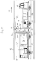
- FIG. 1 shows a tunnel 10 as a railway tunnel with a tunnel wall 12.
- a towing vehicle 16 which is coupled to a wagon 14.
- nozzle hood 18 At the rear end of the towing vehicle 16 there is a nozzle hood 18, and further are on the towing vehicle 16 Water tank 32 and a compressor 34 for the operation of the nozzle hood 18 provided.
- a suction hood 20 is arranged at the front end of the wagon 14, which comprises a suction funnel 22. Also located a dirt container 26 and one on the wagon 14 Fan 28 with an exhaust duct and a motor 30 for the Operation of the suction hood 20.
- the outer dimensions of the nozzle hood 18 are less than the inner cross section of the tunnel 10 in such a way that any existing and projecting from the tunnel wall 12 inwards Parts of the nozzle hood 18 while driving through the Tunnels are not touched.
- the nozzle hood 18 has one elastic hood closure 56, through which the outer dimensions the nozzle hood 18 can be enlarged, but the is always at a distance from the tunnel wall 12 and so on leaves a gap. This gap is important thus an air flow 52 through it into a suction chamber 24 can get through the space between the nozzle hood 18 and the suction hood 20 is formed.
- the mentioned from the Tunnel wall 12 outstanding parts are covered by the hood 56 not damaged because the hood end 56 is elastic is trained and can avoid these parts.
- the suction hood 20 has approximately the same outer dimensions like the nozzle hood 18 and is also with an elastic Hood cover 54 provided the same function how the elastic hood closure 56 of the nozzle hood meets.
- the elastic hood closure 54 also allows one Gap free, through which an air flow 52 into the suction chamber 24 can reach.
- the tunnel 10 or the corresponding tunnel cross section is through the nozzle hood 18 and the suction hood 20 mostly, but not because of the column mentioned completely sealed. However, the seal is sufficient enough that between the nozzle hood 18 and the Suction hood 20 can form the aforementioned suction chamber 24.
- FIG. 2 shows an example of a cross section of a tunnel 10, which is formed by a tunnel tube 36.
- Tunnel lighting 38 and various supply lines are such 40 as required railway facilities intended.
- These parts face the tunnel wall 12 outstanding parts and are allowed to drive with the towing vehicle 16 are not damaged. For this reason a clearance profile is shown in Fig. 2, which the Delimits the area of the tunnel cross-section that is absolutely free is to be kept in order to damage the railway equipment to avoid.
- FIG. 3 shows adjustable segments 48 of the nozzle hood 18 shown, together with an adjustable bulkhead 46. Sensor-controlled pneumatic cylinders are used for the adjustment 50 provided.
- the dashed line 44 indicates the vehicle body of the towing vehicle again.
- Fig. 4 the segments 48 and the bulkhead 46 in the extended Position.
- the pneumatic cylinder 50 By actuating the pneumatic cylinder 50 has the outer circumference of the nozzle hood 18 is enlarged.
- the individual adjustable segments 48 can if necessary overlap and in different parallel planes are located.
- blowing nozzles 58 which are provided on the nozzle hood 18 are and expediently on the adjustable Segments 48 are located.
- the blowing nozzles 58 are on the outer edge the adjustable segments 48 arranged so that they are in are close to the tunnel wall 12.
- FIGS A plurality of blowing nozzles 58 are shown in FIGS a common first ring line 60 and a second Ring line 62 fed; 7 is a third one Ring line 64 and a fourth ring line 66 shown.
- hose connections 70 are provided around connect to adjacent segments 48.
- each blowing nozzle 58 produces each blowing nozzle 58 a compressed air water mixture or a compressed air water jet 68, which is directed to the tunnel wall 12.
- a compressed air water jet 68 becomes the dirt from the tunnel wall 12 solved and transferred into a dusty atmosphere.
- the dusty atmosphere is an air-dirt-water mixture 72 (see FIG. 1), the water content is comparatively small.
- the suction funnel 22 is also the largest Part of the water used for cleaning is also collected. The bottom of the tunnel 10 is therefore subject to practical conditions no drenching.
- the different Ring lines 60 - 66 operated pulsating, so that from only a part of all of the blowing nozzles 58 involved is and the compressed air / water mixture 68 sprays.
- the blow nozzles in this way work pulsating that only a third of the blow nozzles 68 is in use at the same time.
Abstract
Description
Tunnelwände und/oder Tunneldecken unterliegen wegen der den
Tunnel durchfahrenden Fahrzeuge einer starken Verschmutzung,
so daß in regelmäßigen Abständen eine Reinigung erforderlich
ist. Sofern die Tunnelwände glatt mit Kacheln oder dergleichen
Materialien ausgebildet sind, wie dies bei Auto-Tunneln
üblich ist, kann die Reinigung mit Walzenbesensystemen unter
Zugabe von Wasser erfolgen. Eine entsprechende Tunnelreinigungsmaschine
ist durch die deutsche Auslegeschrift 16 58 405
bekannt.Tunnel walls and / or tunnel ceilings are subject to the
Vehicles passing through a tunnel of heavy pollution,
so that cleaning is required at regular intervals
is. If the tunnel walls are smooth with tiles or the like
Materials are formed, as is the case with car tunnels
is usual, cleaning with roller broom systems under
Add water. A corresponding tunnel cleaning machine
is by
Schwieriger gestaltet sich die Reinigung, wenn in dem Tunnel von der Tunnelwand vorspringende Teile, z. B. Verkehrszeichen, Beleuchtungskörper, Belüftungseinrichtungen, Signalanlagen, Oberleitungen, elektrische Versorgungsleitungen und andere Einrichtungen vorhanden sind. Derartige Tunnel sind überwiegend bei Eisenbahnen oder bei U-Bahnen anzutreffen.Cleaning is more difficult when in the tunnel parts projecting from the tunnel wall, e.g. B. traffic signs, Lighting fixtures, ventilation devices, signal systems, Overhead lines, electrical supply lines and other facilities are available. Such tunnels are mainly found on railways or subways.
Durch die deutsche Patentschrift DE 26 58 420 C2 ist für diesen
Zweck ein Tunnelwaschfahrzeug bekannt, welches mit einer
Bürste bzw. einem Walzenbesen unter Zugabe einer für die Reinigung
erforderlichen Waschflüssigkeit arbeitet, wobei gegebenenfalls
auch noch ein Nachspülen mit Spritzdüsen vorgesehen
wird, die der Bürste nachgeordnet sind. Das bekannte Tunnelwaschfahrzeug
ermöglicht es, den richtigen Arbeitsabstand
der Achse der Bürste bzw. der Achse des Walzenbesens von der
Tunnelwand einzuhalten, so daß bei vorspringenden Teilen der
Tunnelwand diesen Hindernissen ausgewichen werden kann, ohne
daß Beschädigungen dieser vorspringenden Teile auftreten.Through the
Der Einsatz von Waschflüssigkeit bewirkt zwar mit der mechanischen Unterstützung durch die Bürste eine Reinigung der Tunnelwände, gleichwohl haften dem bekannten Tunnelwaschfahrzeug gravierende Nachteile an. Die Verwendung von Waschflüssigkeit und Wasser führt zu einer unerwünschten Durchnässung der Verkehrsfläche bzw. des Bodens, und ferner ist zu berücksichtigen, daß neben dem hohen Wasserverbrauch das mit dem Schmutz behaftete Wasser in die Abwasseranlagen gelangt. Außerdem ist es bei Verwendung von Wasser besonders nachteilig, daß durch den Einsatz von Wasser die Gefahr von Kabelbränden bei den im Tunnel vorhandenen elektrischen Leitungen oder auch bei den vorhandenen elektrischen Schaltkästen gegeben ist.The use of washing liquid does indeed work with the mechanical one Assistance by cleaning the brush Tunnel walls, nevertheless stick to the well-known tunnel washing vehicle serious disadvantages. The use of washing liquid and water leads to unwanted soaking the traffic area or the ground, and it must also be taken into account that in addition to the high water consumption with the Dirty water gets into the sewage system. Furthermore it is particularly disadvantageous when using water, that through the use of water there is a risk of cable fires with the existing electrical lines in the tunnel or also given with the existing electrical control boxes is.
Der Erfindung liegt die Aufgabe zugrunde, eine Vorrichtung zur Reinigung von Tunnelwänden und Tunneldecken zu schaffen, welche mit einfachen Mittel eine Durchnässung des Tunnelbodens sowie eine Belastung der Abwasseranlagen mit schmutzigem Wasser vermeidet, und welche auch die Gefahr von Kabelbränden und Kurzschlüssen beseitigt.The invention has for its object a device to create tunnel walls and ceilings, which with simple means wet the tunnel floor as well as pollution of the sewage systems with dirty Water avoids, and which also the danger of cable fires and short circuits eliminated.
Die Lösung dieser Aufgabe erfolgt durch die Merkmale des Patentanspruchs 1.This object is achieved by the features of the patent claim 1.
Die Erfindung beruht auf dem grundlegenden Gedanken, bei der Reinigung von Tunnelwänden durch die Zugabe von Wasser in einen Druckluftstrom ein Aerosol zu erzeugen, welches mit Druck gegen die Tunnelwände gespritzt wird und den Schmutz löst und in eine staubhaltige Atmosphäre in Form eines Luft-SchmutzWassergemisches überführt. Im Vergleich zu bekannten Lösungen wird der Wasserverbrauch dadurch erheblich reduziert, weil dem Druckluftstrom nur vergleichsweise wenig Wasser zugegeben zu werden braucht. Zur Erzeugung des Aerosols dienen mehrere auf dem Umfang einer Düsenhaube angeordnete Blasdüsen mit jeweils einem Injektor.The invention is based on the basic idea that Cleaning tunnel walls by adding water to one Compressed air flow to produce an aerosol that works with pressure is sprayed against the tunnel walls and loosens the dirt and in a dusty atmosphere in the form of an air-dirt-water mixture transferred. Compared to known solutions this significantly reduces water consumption because only relatively little water added to the compressed air flow needs to be. Several are used to generate the aerosol blow nozzles each arranged on the circumference of a nozzle hood an injector.
Zum Absaugen der erzeugten staubhaltigen Atmosphäre wird eine im Abstand zur Düsenhaube angeordnete Saughaube verwendet. Ein wichtiger Gesichtspunkt der Erfindung besteht darin, daß zwischen der Düsenhaube und der Saughaube eine Saugkammer gebildet wird, und dadurch ist gewährleistet, daß die staubhaltige Atmosphäre mit dem gelösten Schmutz nicht zurückbleibt, sondern in einen Schmutzbehälter abgesaugt werden kann.A is used to extract the dust-containing atmosphere suction hood arranged at a distance from the nozzle hood is used. An important aspect of the invention is that a suction chamber is formed between the nozzle hood and the suction hood is, and this ensures that the dusty Atmosphere with the loosened dirt does not remain, but can be sucked into a dirt container.
Sowohl die Düsenhaube als auch die Saughaube erstrecken sich nicht ganz bis an die Tunnelwand, sondern enden im Abstand von der Tunnelwand, so daß die eingangs erwähnten von der Tunnelwand vorstehenden Teile nicht von den beiden Hauben berührt werden, andererseits aber mit dem mit Wasser versehenen Druckluftstrom für die Reinigung beaufschlagt werden. Da nur vergleichsweise wenig Wasser verwendet wird und außerdem die erzeugte staubhaltige Atmosphäre abgesaugt wird, bereitet der Einsatz von Wasser keine Probleme, so daß beispielsweise Kabelbrände oder andere durch eine Einwirkung von Wasser mögliche Folgeschäden vermieden sind. Die Abwasseranlagen werden durch die Reinigung der Tunnelwände überhaupt nicht belastet, weil die staubhaltige Atmosphäre in einen geschlossenen Schmutzbehälter aufgefangen wird. Aus diesem Grunde unterbleibt in vorteilhafter Weise auch eine Durchnässung des Tunnelbodens.Both the nozzle hood and the suction hood extend not all the way to the tunnel wall, but end at a distance from the tunnel wall, so that the aforementioned from the Parts of the tunnel wall do not touch the two hoods be, but on the other hand with the water Compressed air flow for cleaning. Because only comparatively little water is used and also the generated dust-containing atmosphere is extracted, the Use of water no problems, for example cable fires or others possible through exposure to water Consequential damage is avoided. The sewage systems are not burdened at all by cleaning the tunnel walls, because the dusty atmosphere in a closed Dirt container is collected. For this reason, it is omitted advantageously also a wetting of the tunnel floor.
Die erfindungsgemäße Vorrichtung zur Durchführung des Verfahrens umfaßt die schon erwähnte Düsenhaube, die längs des Tunnels verfahrbar ist und sich im Abstand von der Tunnelwand bzw. von der Tunneldecke erstreckt. Auf dem Umfang der Düsenhaube sind verteilt mehrere mit einem Injektor versehene Blasdüsen angeordnet, die auf die Tunnelwand gerichtet sind.The inventive device for performing the method includes the nozzle hood already mentioned, along the tunnel is movable and at a distance from the tunnel wall or extends from the tunnel ceiling. On the circumference of the nozzle hood are several distributed with an injector Blow nozzles arranged, which are directed to the tunnel wall.
Aus den im Sicherheitsabstand von der Tunnelwand angeordneten Düsen tritt ein auf die Tunnelwand gerichtetes Druckluftwassergemisch aus, welches ein Aerosol bildet und die auf der Tunnelwand festsitzenden Ablagerungen und den Schmutz und Staub löst und eine staubhaltige Atmosphäre erzeugt. Dabei ist es von Vorteil, daß der Tunnel in Fahrtrichtung nach vorne durch die Düsenhaube überwiegend abgedichtet ist.From those arranged at a safe distance from the tunnel wall A compressed air / water mixture is directed towards the tunnel wall which forms an aerosol and which on the Debris and dirt and stuck deposits Dust dissolves and creates a dusty atmosphere. Here it is advantageous that the tunnel is facing forward is largely sealed by the nozzle hood.
In Fahrtrichtung gesehen hinter der Düsenhaube umfaßt die erfindungsgemäße Vorrichtung die ebenfalls verfahrbar angeordnete Saughaube mit im wesentlichen gleichen Abmessungen und gleicher Form wie die Düsenhaube. Die Saughaube besitzt mindestens eine Sauganordnung zum Absaugen der staubhaltigen Atmosphäre, die sich in dem Raum zwischen der Düsenhaube und der Saughaube befindet. Dabei ist es weiterhin von Vorteil, daß der Tunnel durch die Saughaube weitestgehend in Fahrtrichtung nach hinten abgedichtet wird, so daß zwischen der Düsenhaube einerseits und der Saughaube andererseits eine Saugkammer gebildet wird.Seen in the direction of travel behind the nozzle hood includes the invention Device also arranged to be movable Suction hood with essentially the same dimensions and same shape as the nozzle hood. The suction hood has at least a suction arrangement for extracting the dusty atmosphere, which is in the space between the nozzle hood and the suction hood is located. It is still an advantage that the tunnel through the suction hood largely in the direction of travel is sealed to the rear so that between the Nozzle hood on the one hand and the suction hood on the other Suction chamber is formed.
In zweckmäßiger Ausgestaltung der Erfindung umfaßt die Düsenhaube verstellbare Segmente, an denen jeweils eine Vielzahl von Blasdüsen angeordnet sind, und die radial in Richtung auf die Tunnelwand sowie in entgegengesetzte Richtung verstellbar sind. In an expedient embodiment of the invention, the nozzle hood comprises adjustable segments, each with a variety of blowing nozzles are arranged, and the radially towards the tunnel wall and adjustable in the opposite direction are.
Durch die mittels pneumatischer Zylinder verstellbaren Segmente läßt sich der Umfang und die äußere Kontur der Düsenhaube verändern, nämlich vergrößern oder verkleinern. Dadurch ist es möglich, die Größe der Düsenhaube an die Größe des jeweiligen Tunnels anzupassen.Thanks to the segments adjustable by means of pneumatic cylinders the circumference and the outer contour of the nozzle hood change, namely enlarge or reduce. Thereby it is possible to resize the nozzle hood to the size of each Adapt tunnels.
Entsprechend ist in einer anderen vorteilhaften Ausgestaltung der Erfindung vorgesehen, daß auch die Größe bzw. die äußeren Abmessungen der Saughaube veränderbar sind. Zu diesem Zweck können ebenfalls verstellbare Segmente oder auch verstellbare Schottwände vorgesehen sein.This is corresponding in another advantageous embodiment the invention provided that the size or the outer Dimensions of the suction hood are changeable. To this end can also be adjustable segments or also adjustable Bulkheads may be provided.
Eine weitere zweckmäßige Ausgestaltung der Erfindung sieht vor, daß der äußere Rand sowohl der Düsenhaube als auch der Saughaube mit einem elastischen Haubenabschluß versehen ist. Dieser elastische Haubenabschluß erstreckt sich jeweils weiter in Richtung auf die Tunnelwand als die Düsenhaube und die Saughaube selbst. Bei Bewegung der erfindungsgemäßen Vorrichtung in Fahrtrichtung können daher die elastischen Haubenabschlüsse durchaus mit den von der Tunnelwand hervorspringenden Teilen und bahntechnischen Einrichtungen in Berührung kommen. Dies ist jedoch nicht störend, denn wegen der elastischen Ausgestaltung der Haubenabschlüsse z. B. in Form von Gummi werden die bahntechnischen Einrichtungen nicht beschädigt. Andererseits läßt sich durch die elastischen Haubenabschlüsse eine noch bessere wenn auch nicht vollständige Abdichtung des Tunnels durch die Düsenhaube und durch die Saughaube erreichen, wodurch die Wirksamkeit der zwischen der Düsenhaube und der Saughaube befindlichen Saugkammer erhöht wird.Another expedient embodiment of the invention provides before that the outer edge of both the nozzle hood and the Suction hood is provided with an elastic hood end. This elastic hood closure extends further towards the tunnel wall as the nozzle hood and the Suction hood itself. When moving the device according to the invention in the direction of travel, therefore, the elastic hood ends definitely with those that protrude from the tunnel wall Parts and railway equipment in contact come. However, this is not annoying because of the elastic Design of the hood ends z. B. in the form of Rubber will not damage the railway equipment. On the other hand, the elastic hood ends an even better if not complete seal of the tunnel through the nozzle hood and through the suction hood achieve, reducing the effectiveness of between the nozzle hood and the suction hood located suction chamber increased becomes.
Weitere zweckmäßige Ausgestaltungen und vorteilhafte Weiterbildungen der Erfindung sind in den Unteransprüchen angegeben.Further expedient refinements and advantageous developments the invention are specified in the subclaims.
Anhand des in der Zeichnung dargestellten Ausführungsbeispiels wird die Erfindung nachfolgend näher erläutert. Es zeigen:
- Fig. 1
- eine schematische Seitenansicht einer auf Schienenfahrzeugen angeordneten Vorrichtung in einem Tunnel,
- Fig. 2
- eine Querschnittansicht eines Tunnels ohne die erfindungsgemäße Vorrichtung,
- Fig. 3
- eine Querschnittansicht eines Tunnels mit einer erfindungsgemäßen Vorrichtung mit der Ansicht einer Düsenhaube mit verstellbaren Segmenten,
- Fig. 4
- eine Ansicht gemäß Fig. 3, wobei die verstellbaren Segmente der Düsenhaube ausgefahren sind,
- Fig. 5u.6
- jeweils eine Teildarstellung von Blasdüsen in einer Draufsicht auf die Düsenhaube, und
- Fig. 7
- einen Längsschnitt einer Teildarstellung von Blasdüsen.
- Fig. 1
- 2 shows a schematic side view of a device arranged on rail vehicles in a tunnel,
- Fig. 2
- 2 shows a cross-sectional view of a tunnel without the device according to the invention,
- Fig. 3
- 2 shows a cross-sectional view of a tunnel with a device according to the invention with the view of a nozzle hood with adjustable segments,
- Fig. 4
- 3, the adjustable segments of the nozzle hood being extended,
- Fig. 5u.6
- each a partial representation of blowing nozzles in a plan view of the nozzle hood, and
- Fig. 7
- a longitudinal section of a partial view of blow nozzles.
Die Darstellung in Fig. 1 zeigt einen Tunnel 10 als Eisenbahntunnel
mit einer Tunnelwand 12. In dem Tunnel 10 fährt in
der durch den Pfeil A angedeuteten Fahrtrichtung ein Zugfahrzeug
16, welches mit einem Waggon 14 gekoppelt ist.The illustration in FIG. 1 shows a
Am hinteren Ende des Zugfahrzeuges 16 befindet sich eine Düsenhaube
18, und ferner sind auf dem Zugfahrzeug 16 noch ein
Wassertank 32 sowie ein Kompressor 34 für den Betrieb der Düsenhaube
18 vorgesehen.At the rear end of the towing
Am vorderen Ende des Waggons 14 ist eine Saughaube 20 angeordnet,
die einen Saugtrichter 22 umfaßt. Außerdem befinden
sich auf dem Waggon 14 noch ein Schmutzbehälter 26 sowie ein
Ventilator 28 mit einem Abluftkanal und ein Motor 30 für den
Betrieb der Saughaube 20.A
Die äußeren Abmessungen der Düsenhaube 18 sind geringer als
der innere Querschnitt des Tunnels 10, und zwar derart, daß
eventuell vorhandene und von der Tunnelwand 12 nach innen ragende
Teile von der Düsenhaube 18 während der Fahrt durch den
Tunnel nicht berührt werden. Die Düsenhaube 18 besitzt einen
elastischen Haubenabschluß 56, durch welchen die äußeren Abmessungen
der Düsenhaube 18 vergrößert werden, der sich jedoch
stets im Abstand von der Tunnelwand 12 befindet und so-mit
einen Spalt frei läßt. Dieser Spalt ist von Bedeutung,
damit ein Luftstrom 52 durch ihn hindurch in eine Saugkammer
24 gelangen kann, die durch den Raum zwischen der Düsenhaube
18 und der Saughaube 20 gebildet wird. Die erwähnten von der
Tunnelwand 12 hervorragenden Teile werden durch den Haubenabschluß
56 nicht beschädigt, weil der Haubenabschluß 56 elastisch
ausgebildet ist und diesen Teilen ausweichen kann.The outer dimensions of the
Die Saughaube 20 besitzt etwa die gleichen äußeren Abmessungen
wie die Düsenhaube 18 und ist ebenfalls mit einem elastischen
Haubenabschluß 54 versehen, der die gleiche Funktion
wie der elastische Haubenabschluß 56 der Düsenhaube erfüllt.
Insbesondere läßt auch der elastische Haubenabschluß 54 einen
Spalt frei, durch den ein Luftstrom 52 in die Saugkammer 24
gelangen kann. Der Tunnel 10 bzw. der entsprechende Tunnelquerschnitt
wird also durch die Düsenhaube 18 und die Saughaube
20 überwiegend, aber wegen der erwähnten Spalte nicht
vollständig abgedichtet. Die Abdichtung ist jedoch hinreichend
genug, daß sich zwischen der Düsenhaube 18 und der
Saughaube 20 die erwähnte Saugkammer 24 ausbilden kann. The
Fig. 2 zeigt ein Beispiel eines Querschnittes eines Tunnels
10, der durch eine Tunnelröhre 36 gebildet wird. In üblicher
Weise sind eine Tunnelbeleuchtung 38 sowie verschiedene Versorgungsleitungen
40 als erforderliche bahntechnische Einrichtungen
vorgesehen. Diese Teile stellen von der Tunnelwand
12 hervorragende Teile dar und dürfen während der Fahrt mit
dem Zugfahrzeug 16 nicht beschädigt werden. Aus diesem Grunde
ist in Fig. 2 ein Lichtraumprofil dargestellt, welches den
Bereich des Tunnelquerschnitts abgrenzt, der unbedingt frei
zu halten ist, um Beschädigungen der bahntechnischen Einrichtungen
zu vermeiden.2 shows an example of a cross section of a
In Fig. 3 sind verstellbare Segmente 48 der Düsenhaube 18
dargestellt, zusammen mit einer verstellbaren Schottwand 46.
Für die Verstellung sind sensorgesteuerte Pneumatikzylinder
50 vorgesehen. Die gestrichelte Linie 44 gibt den Fahrzeugaufbau
des Zugfahrzeuges wieder.3 shows
Zur Verdeutlichung der Möglichkeit des Verstellens zeigt Fig.
4 die Segmente 48 sowie die Schottwand 46 in ausgefahrener
Position. Durch Betätigung der Pneumatikzylinder 50 hat sich
dabei der äußere Umfang der Düsenhaube 18 vergrößert. Die
einzelnen verstellbaren Segmente 48 können sich gegebenenfalls
überlappen und in unterschiedlichen Parallelen Ebenen
befinden. Entsprechendes gilt auch für die Schottwand 46, von
der mehrere vorgesehen werden können.To illustrate the possibility of adjustment, Fig.
4 the
Fig. 5 - 7 zeigen Blasdüsen 58, die an der Düsenhaube 18 vorgesehen
sind und sich zweckmäßigerweise an den verstellbaren
Segmenten 48 befinden. Die Blasdüsen 58 sind am äußeren Rand
der verstellbaren Segmente 48 angeordnet, so daß sie sich im
geringen Abstand zur Tunnelwand 12 befinden.5-7 show blowing nozzles 58 which are provided on the
Mehrere Blasdüsen 58 werden gemäß Fig. 5 und 6 jeweils von
einer gemeinsamen ersten Ringleitung 60 und einer zweiten
Ringleitung 62 gespeist; in Fig. 7 sind noch eine dritte
Ringleitung 64 und eine vierte Ringleitung 66 dargestellt. Um
eine Verbindung zu benachbarten Segmenten 48 herzustellen,
sind Schlauchverbindungen 70 vorgesehen.A plurality of blowing
Mit Hilfe des in dem Wassertank 32 (vgl. Fig. 1) befindlichen
Wassers sowie mit Hilfe des Kompressors 34 erzeugt jede Blasdüse
58 ein Druckluftwassergemisch bzw. einen Druckluftwasserstrahl
68, der auf die Tunnelwand 12 gerichtet ist. Durch
den Druckluftwasserstrahl 68 wird der Schmutz von der Tunnelwand
12 gelöst und in eine staubhaltige Atmosphäre überführt.With the help of the one in the water tank 32 (see FIG. 1)
Water as well as with the help of the
Durch den Betrieb des Ventilators 28 (vgl. Fig. 1) sowie
durch den Saugtrichter 22 der Saughaube 20 bildet sich zwischen
der Saughaube 20 und der Düsenhaube 18 die Saugkammer
24 aus, wodurch die in Fig. 1 gezeigten Luftströme 52 in die
Saugkammer 24 fließen. Die erwähnte schmutzhaltige Atmosphäre
wird somit durch den Saugtrichter 22 in den Schmutzbehälter
26 abgesaugt. Solche Schmutzbehälter sind für sich gesehen
bei Straßenreinigungsfahrzeugen bekannt. Der Staub wird in
dem Schmutzbehälter 26 niedergeschlagen und kann zu einem
späteren Zeitpunkt außerhalb des Tunnels 10 entleert werden.Through the operation of the fan 28 (see FIG. 1) and
through the
Bei der staubhaltigen Atmosphäre handelt es sich um ein Luft-Schmutz-Wasser-Gemisch
72 (vgl. Fig. 1), wobei der Wasseranteil
vergleichsweise gering ist. Außerdem wird durch den
Saugtrichter 22 neben dem gelösten Schmutz auch der größte
Teil des für die Reinigung verwendeten Wasseranteils mit aufgefangen.
Der Boden des Tunnels 10 unterliegt damit praktisch
keiner Durchnässung. The dusty atmosphere is an air-dirt-water mixture
72 (see FIG. 1), the water content
is comparatively small. In addition, the
In addition to the loosened dirt, the
In einer vorteilhaften Arbeitsweise werden die unterschiedlichen
Ringleitungen 60 - 66 pulsierend betrieben, so daß von
allen beteiligten Blasdüsen 58 jeweils nur ein Teil in Betrieb
ist und das Druckluftwassergemisch 68 versprüht. Als
zweckmäßig hat es sich erwiesen, wenn die Blasdüsen derart
pulsierend arbeiten, daß immer nur ein Drittel der Blasdüsen
68 gleichzeitig im Einsatz ist.In an advantageous way of working, the different
Ring lines 60 - 66 operated pulsating, so that from
only a part of all of the blowing
Claims (10)
Applications Claiming Priority (2)
| Application Number | Priority Date | Filing Date | Title |
|---|---|---|---|
| DE19721414 | 1997-05-22 | ||
| DE19721414 | 1997-05-22 |
Publications (3)
| Publication Number | Publication Date |
|---|---|
| EP0879919A2 true EP0879919A2 (en) | 1998-11-25 |
| EP0879919A3 EP0879919A3 (en) | 1999-12-01 |
| EP0879919B1 EP0879919B1 (en) | 2003-08-27 |
Family
ID=7830177
Family Applications (1)
| Application Number | Title | Priority Date | Filing Date |
|---|---|---|---|
| EP98109347A Expired - Lifetime EP0879919B1 (en) | 1997-05-22 | 1998-05-22 | Apparatus for cleaning tunnel walls and/or ceilings |
Country Status (4)
| Country | Link |
|---|---|
| EP (1) | EP0879919B1 (en) |
| AT (1) | ATE248258T1 (en) |
| DE (1) | DE59809374D1 (en) |
| ES (1) | ES2206790T3 (en) |
Cited By (3)
| Publication number | Priority date | Publication date | Assignee | Title |
|---|---|---|---|---|
| WO2010075828A1 (en) * | 2008-12-30 | 2010-07-08 | Bes' T Global Engineering Ltd. | Method and apparatus for cleaning the superstructure and tunnel walls |
| CN106836099A (en) * | 2016-12-27 | 2017-06-13 | 苏州大方特种车股份有限公司 | Tunnel cleaning vehicle |
| CN109423971A (en) * | 2017-08-24 | 2019-03-05 | 中铁华铁工程设计集团有限公司 | Plane jet formula subway tunnel purger |
Families Citing this family (1)
| Publication number | Priority date | Publication date | Assignee | Title |
|---|---|---|---|---|
| DE102019100301A1 (en) | 2019-01-08 | 2020-07-09 | Cft Gmbh Compact Filter Technic | Tunnel cleaning train |
Citations (2)
| Publication number | Priority date | Publication date | Assignee | Title |
|---|---|---|---|---|
| DE1658405A1 (en) | 1966-04-12 | 1970-11-05 | Materiel De Voirie | Self-propelled device for cleaning tunnel walls |
| DE2658420A1 (en) | 1976-01-14 | 1977-07-21 | Zellinger Gmbh | TUNNEL WASHING VEHICLE |
Family Cites Families (1)
| Publication number | Priority date | Publication date | Assignee | Title |
|---|---|---|---|---|
| GB186970A (en) * | 1900-01-01 |
-
1998
- 1998-05-22 EP EP98109347A patent/EP0879919B1/en not_active Expired - Lifetime
- 1998-05-22 AT AT98109347T patent/ATE248258T1/en not_active IP Right Cessation
- 1998-05-22 DE DE59809374T patent/DE59809374D1/en not_active Expired - Fee Related
- 1998-05-22 ES ES98109347T patent/ES2206790T3/en not_active Expired - Lifetime
Patent Citations (2)
| Publication number | Priority date | Publication date | Assignee | Title |
|---|---|---|---|---|
| DE1658405A1 (en) | 1966-04-12 | 1970-11-05 | Materiel De Voirie | Self-propelled device for cleaning tunnel walls |
| DE2658420A1 (en) | 1976-01-14 | 1977-07-21 | Zellinger Gmbh | TUNNEL WASHING VEHICLE |
Cited By (5)
| Publication number | Priority date | Publication date | Assignee | Title |
|---|---|---|---|---|
| WO2010075828A1 (en) * | 2008-12-30 | 2010-07-08 | Bes' T Global Engineering Ltd. | Method and apparatus for cleaning the superstructure and tunnel walls |
| EP2305892A2 (en) * | 2008-12-30 | 2011-04-06 | BES't Global Engineering Ltd. | Process and device for cleaning track bed and tunnel walls |
| EP2305892A3 (en) * | 2008-12-30 | 2012-10-31 | Rodinia Technologies Ltd. | Process and device for cleaning track bed and tunnel walls |
| CN106836099A (en) * | 2016-12-27 | 2017-06-13 | 苏州大方特种车股份有限公司 | Tunnel cleaning vehicle |
| CN109423971A (en) * | 2017-08-24 | 2019-03-05 | 中铁华铁工程设计集团有限公司 | Plane jet formula subway tunnel purger |
Also Published As
| Publication number | Publication date |
|---|---|
| ES2206790T3 (en) | 2004-05-16 |
| EP0879919B1 (en) | 2003-08-27 |
| DE59809374D1 (en) | 2003-10-02 |
| ATE248258T1 (en) | 2003-09-15 |
| EP0879919A3 (en) | 1999-12-01 |
Similar Documents
| Publication | Publication Date | Title |
|---|---|---|
| EP0337048B1 (en) | Railway machine for vacuum cleaning a track superstructure | |
| EP3365216B1 (en) | Pneumatic footplate cleaning | |
| EP3418450B1 (en) | Tunnel cleaning device | |
| DE1954950U (en) | DEVICE TRAINED AS A VEHICLE FOR CLEANING ROADS OD. DGL. | |
| EP0637531B1 (en) | Apparatus for cleaning a two-wheeled vehicle, especially a bicycle | |
| DE112017007818T5 (en) | FLUID EMISSION MACHINE | |
| WO2010075828A1 (en) | Method and apparatus for cleaning the superstructure and tunnel walls | |
| DE4108673A1 (en) | Process for continuous cleaning of railway ballast - involves using hood equipped with compressed air and high pressure water jets, attached to constantly moving vehicle | |
| EP0879919B1 (en) | Apparatus for cleaning tunnel walls and/or ceilings | |
| DE2548078C3 (en) | A suction device assigned to a movable scarfing device | |
| EP3420139B1 (en) | Sand removal device | |
| EP0887470A1 (en) | Device for the cleaning of the grooves of rails | |
| EP0563081B1 (en) | Process for cleaning a drop separator and drop separator with cleaning device | |
| DE2617635C2 (en) | Vacuum cleaner, in particular vacuum cleaner designed as a vehicle or mobile device | |
| DE102006007962A1 (en) | Method for cleaning car body prior to painting, comprises use of pressure guided through movable arms | |
| DE102020120183A1 (en) | Rail vehicle with rail clearer | |
| DE19522443A1 (en) | Rail cleaning method using rail vehicle | |
| DE19622236A1 (en) | Rail vehicle for cleaning surface of rail track | |
| DE3927980C1 (en) | Appts. to remove lint from cleaning installation - has cleaning belt associated with suction nozzle with overflow shuttles | |
| DE102019100301A1 (en) | Tunnel cleaning train | |
| DE202013103829U1 (en) | Drying device and vehicle treatment system | |
| DE102019002217B4 (en) | Surface cleaning vehicle with a suction device for edge suction | |
| DE102019001845A1 (en) | Surface cleaning vehicle with an adjustable suction device to reduce a flow cross-section | |
| WO2023131652A1 (en) | Conditioning apparatus for cleaning and/or drying a track bed formed from ballast stones, and conditioning method using said conditioning apparatus | |
| DE10111350A1 (en) | Cleaning method for dirty or contaminated roadways, etc. uses vehicle with cleaning appliance to remove solids, apply wet cleaning material, and suck-off residue |
Legal Events
| Date | Code | Title | Description |
|---|---|---|---|
| PUAI | Public reference made under article 153(3) epc to a published international application that has entered the european phase |
Free format text: ORIGINAL CODE: 0009012 |
|
| AK | Designated contracting states |
Kind code of ref document: A2 Designated state(s): AT BE CH CY DE DK ES FI FR GB GR IE IT LI LU NL PT SE |
|
| AX | Request for extension of the european patent |
Free format text: AL;LT;LV;MK;RO;SI |
|
| RAP1 | Party data changed (applicant data changed or rights of an application transferred) |
Owner name: SCHOERLING-BROCK GMBH |
|
| PUAL | Search report despatched |
Free format text: ORIGINAL CODE: 0009013 |
|
| AK | Designated contracting states |
Kind code of ref document: A3 Designated state(s): AT BE CH CY DE DK ES FI FR GB GR IE IT LI LU MC NL PT SE |
|
| AX | Request for extension of the european patent |
Free format text: AL;LT;LV;MK;RO;SI |
|
| 17P | Request for examination filed |
Effective date: 20000425 |
|
| AKX | Designation fees paid |
Free format text: AT BE CH CY DE DK ES FI FR GB GR IE IT LI LU NL PT SE |
|
| 17Q | First examination report despatched |
Effective date: 20020327 |
|
| GRAH | Despatch of communication of intention to grant a patent |
Free format text: ORIGINAL CODE: EPIDOS IGRA |
|
| GRAH | Despatch of communication of intention to grant a patent |
Free format text: ORIGINAL CODE: EPIDOS IGRA |
|
| GRAA | (expected) grant |
Free format text: ORIGINAL CODE: 0009210 |
|
| RIN1 | Information on inventor provided before grant (corrected) |
Inventor name: BROCK, ALBERT |
|
| AK | Designated contracting states |
Designated state(s): AT BE CH CY DE DK ES FI FR GB GR IE IT LI LU NL PT SE |
|
| PG25 | Lapsed in a contracting state [announced via postgrant information from national office to epo] |
Ref country code: IE Free format text: LAPSE BECAUSE OF FAILURE TO SUBMIT A TRANSLATION OF THE DESCRIPTION OR TO PAY THE FEE WITHIN THE PRESCRIBED TIME-LIMIT Effective date: 20030827 Ref country code: FI Free format text: LAPSE BECAUSE OF FAILURE TO SUBMIT A TRANSLATION OF THE DESCRIPTION OR TO PAY THE FEE WITHIN THE PRESCRIBED TIME-LIMIT Effective date: 20030827 Ref country code: CY Free format text: LAPSE BECAUSE OF FAILURE TO SUBMIT A TRANSLATION OF THE DESCRIPTION OR TO PAY THE FEE WITHIN THE PRESCRIBED TIME-LIMIT Effective date: 20030827 |
|
| REG | Reference to a national code |
Ref country code: GB Ref legal event code: FG4D Free format text: NOT ENGLISH |
|
| REG | Reference to a national code |
Ref country code: CH Ref legal event code: EP |
|
| REG | Reference to a national code |
Ref country code: IE Ref legal event code: FG4D Free format text: GERMAN |
|
| REF | Corresponds to: |
Ref document number: 59809374 Country of ref document: DE Date of ref document: 20031002 Kind code of ref document: P |
|
| PG25 | Lapsed in a contracting state [announced via postgrant information from national office to epo] |
Ref country code: GR Free format text: LAPSE BECAUSE OF FAILURE TO SUBMIT A TRANSLATION OF THE DESCRIPTION OR TO PAY THE FEE WITHIN THE PRESCRIBED TIME-LIMIT Effective date: 20031127 Ref country code: DK Free format text: LAPSE BECAUSE OF FAILURE TO SUBMIT A TRANSLATION OF THE DESCRIPTION OR TO PAY THE FEE WITHIN THE PRESCRIBED TIME-LIMIT Effective date: 20031127 |
|
| GBT | Gb: translation of ep patent filed (gb section 77(6)(a)/1977) |
Effective date: 20031119 |
|
| REG | Reference to a national code |
Ref country code: SE Ref legal event code: TRGR |
|
| PG25 | Lapsed in a contracting state [announced via postgrant information from national office to epo] |
Ref country code: PT Free format text: LAPSE BECAUSE OF FAILURE TO SUBMIT A TRANSLATION OF THE DESCRIPTION OR TO PAY THE FEE WITHIN THE PRESCRIBED TIME-LIMIT Effective date: 20040127 |
|
| REG | Reference to a national code |
Ref country code: IE Ref legal event code: FD4D |
|
| REG | Reference to a national code |
Ref country code: ES Ref legal event code: FG2A Ref document number: 2206790 Country of ref document: ES Kind code of ref document: T3 |
|
| PG25 | Lapsed in a contracting state [announced via postgrant information from national office to epo] |
Ref country code: LU Free format text: LAPSE BECAUSE OF NON-PAYMENT OF DUE FEES Effective date: 20040522 |
|
| ET | Fr: translation filed | ||
| PLBE | No opposition filed within time limit |
Free format text: ORIGINAL CODE: 0009261 |
|
| STAA | Information on the status of an ep patent application or granted ep patent |
Free format text: STATUS: NO OPPOSITION FILED WITHIN TIME LIMIT |
|
| 26N | No opposition filed |
Effective date: 20040528 |
|
| PGFP | Annual fee paid to national office [announced via postgrant information from national office to epo] |
Ref country code: ES Payment date: 20080523 Year of fee payment: 11 Ref country code: CH Payment date: 20080523 Year of fee payment: 11 |
|
| PGFP | Annual fee paid to national office [announced via postgrant information from national office to epo] |
Ref country code: AT Payment date: 20080521 Year of fee payment: 11 |
|
| PGFP | Annual fee paid to national office [announced via postgrant information from national office to epo] |
Ref country code: BE Payment date: 20080527 Year of fee payment: 11 Ref country code: IT Payment date: 20080524 Year of fee payment: 11 |
|
| PGFP | Annual fee paid to national office [announced via postgrant information from national office to epo] |
Ref country code: SE Payment date: 20080523 Year of fee payment: 11 Ref country code: NL Payment date: 20080523 Year of fee payment: 11 |
|
| PGFP | Annual fee paid to national office [announced via postgrant information from national office to epo] |
Ref country code: GB Payment date: 20080522 Year of fee payment: 11 |
|
| BERE | Be: lapsed |
Owner name: *SCHORLING-BROCK G.M.B.H. Effective date: 20090531 |
|
| REG | Reference to a national code |
Ref country code: CH Ref legal event code: PL |
|
| GBPC | Gb: european patent ceased through non-payment of renewal fee |
Effective date: 20090522 |
|
| PG25 | Lapsed in a contracting state [announced via postgrant information from national office to epo] |
Ref country code: LI Free format text: LAPSE BECAUSE OF NON-PAYMENT OF DUE FEES Effective date: 20090531 Ref country code: CH Free format text: LAPSE BECAUSE OF NON-PAYMENT OF DUE FEES Effective date: 20090531 Ref country code: AT Free format text: LAPSE BECAUSE OF NON-PAYMENT OF DUE FEES Effective date: 20090522 |
|
| PGFP | Annual fee paid to national office [announced via postgrant information from national office to epo] |
Ref country code: DE Payment date: 20091111 Year of fee payment: 12 |
|
| NLV4 | Nl: lapsed or anulled due to non-payment of the annual fee |
Effective date: 20091201 |
|
| PG25 | Lapsed in a contracting state [announced via postgrant information from national office to epo] |
Ref country code: NL Free format text: LAPSE BECAUSE OF NON-PAYMENT OF DUE FEES Effective date: 20091201 |
|
| REG | Reference to a national code |
Ref country code: FR Ref legal event code: ST Effective date: 20100129 |
|
| PG25 | Lapsed in a contracting state [announced via postgrant information from national office to epo] |
Ref country code: FR Free format text: LAPSE BECAUSE OF NON-PAYMENT OF DUE FEES Effective date: 20090602 |
|
| PGFP | Annual fee paid to national office [announced via postgrant information from national office to epo] |
Ref country code: FR Payment date: 20080519 Year of fee payment: 11 |
|
| PG25 | Lapsed in a contracting state [announced via postgrant information from national office to epo] |
Ref country code: GB Free format text: LAPSE BECAUSE OF NON-PAYMENT OF DUE FEES Effective date: 20090522 |
|
| PG25 | Lapsed in a contracting state [announced via postgrant information from national office to epo] |
Ref country code: BE Free format text: LAPSE BECAUSE OF NON-PAYMENT OF DUE FEES Effective date: 20090531 |
|
| REG | Reference to a national code |
Ref country code: ES Ref legal event code: FD2A Effective date: 20090523 |
|
| PG25 | Lapsed in a contracting state [announced via postgrant information from national office to epo] |
Ref country code: ES Free format text: LAPSE BECAUSE OF NON-PAYMENT OF DUE FEES Effective date: 20090523 |
|
| PG25 | Lapsed in a contracting state [announced via postgrant information from national office to epo] |
Ref country code: IT Free format text: LAPSE BECAUSE OF NON-PAYMENT OF DUE FEES Effective date: 20090522 |
|
| PG25 | Lapsed in a contracting state [announced via postgrant information from national office to epo] |
Ref country code: DE Free format text: LAPSE BECAUSE OF NON-PAYMENT OF DUE FEES Effective date: 20101201 |
|
| PG25 | Lapsed in a contracting state [announced via postgrant information from national office to epo] |
Ref country code: SE Free format text: LAPSE BECAUSE OF NON-PAYMENT OF DUE FEES Effective date: 20090523 |