EP3420139B1 - Entsandungseinrichtung - Google Patents
Entsandungseinrichtung Download PDFInfo
- Publication number
- EP3420139B1 EP3420139B1 EP17719528.6A EP17719528A EP3420139B1 EP 3420139 B1 EP3420139 B1 EP 3420139B1 EP 17719528 A EP17719528 A EP 17719528A EP 3420139 B1 EP3420139 B1 EP 3420139B1
- Authority
- EP
- European Patent Office
- Prior art keywords
- air
- rail vehicle
- sand
- baffle
- air flow
- Prior art date
- Legal status (The legal status is an assumption and is not a legal conclusion. Google has not performed a legal analysis and makes no representation as to the accuracy of the status listed.)
- Active
Links
Images

Classifications
-
- E—FIXED CONSTRUCTIONS
- E01—CONSTRUCTION OF ROADS, RAILWAYS, OR BRIDGES
- E01H—STREET CLEANING; CLEANING OF PERMANENT WAYS; CLEANING BEACHES; DISPERSING OR PREVENTING FOG IN GENERAL CLEANING STREET OR RAILWAY FURNITURE OR TUNNEL WALLS
- E01H8/00—Removing undesirable matter from the permanent way of railways; Removing undesirable matter from tramway rails
- E01H8/10—Removing undesirable matter from rails, flange grooves, or the like railway parts, e.g. removing ice from contact rails, removing mud from flange grooves
- E01H8/105—Pneumatically or hydraulically loosening, removing or dislodging undesirable matter, e.g. removing by blowing, flushing, suction; Application of melting liquids; Loosening or removing by means of heat, e.g. cleaning by plasma torches, drying by burners
-
- E—FIXED CONSTRUCTIONS
- E01—CONSTRUCTION OF ROADS, RAILWAYS, OR BRIDGES
- E01H—STREET CLEANING; CLEANING OF PERMANENT WAYS; CLEANING BEACHES; DISPERSING OR PREVENTING FOG IN GENERAL CLEANING STREET OR RAILWAY FURNITURE OR TUNNEL WALLS
- E01H8/00—Removing undesirable matter from the permanent way of railways; Removing undesirable matter from tramway rails
- E01H8/10—Removing undesirable matter from rails, flange grooves, or the like railway parts, e.g. removing ice from contact rails, removing mud from flange grooves
-
- B—PERFORMING OPERATIONS; TRANSPORTING
- B61—RAILWAYS
- B61F—RAIL VEHICLE SUSPENSIONS, e.g. UNDERFRAMES, BOGIES OR ARRANGEMENTS OF WHEEL AXLES; RAIL VEHICLES FOR USE ON TRACKS OF DIFFERENT WIDTH; PREVENTING DERAILING OF RAIL VEHICLES; WHEEL GUARDS, OBSTRUCTION REMOVERS OR THE LIKE FOR RAIL VEHICLES
- B61F19/00—Wheel guards; Bumpers; Obstruction removers or the like
Definitions
- the invention relates to a sanding device for a rail vehicle
- sand clearing machines are used which are arranged on motor vehicles and which remove the sand, for example by means of a sand cutter. These machines can also be arranged on the front of a rail vehicle that is traveling slowly along the route.
- the known sand clearing methods have a disadvantage, however, since they are unable to remove small sand deposits on the rail head. However, these small sand deposits, which do not represent a restriction for driving safety, cause massively increased wear on the rail vehicle wheels.
- the invention is therefore based on the object of specifying a sanding device for a rail vehicle which is maintenance-free and wear-free and which does not require any connections to electrical or pneumatic systems of the rail vehicle.
- a sanding device for a rail vehicle which has at least one air guiding device with fastening means for arranging the air guiding device the rail vehicle, wherein the at least one air guiding device is designed such that the air flow caused by the movement of the rail vehicle is directed to a position directly in front of the wheels of an axle of the rail vehicle leading in the direction of travel.
- sand removal device has no moving parts or brushes and also does not require any connections to electrical or pneumatic systems of the rail vehicle.
- a desanding device according to the invention can be retrofitted to existing vehicles.
- the invention provides that the air flow directed directly in front of the wheels of an axle of the rail vehicle leading in the direction of travel comprises a horizontal speed component normal to the direction of movement of the rail vehicle. This is ensured by guiding the air flow in a corresponding direction through the air guiding device.
- the angle of the air flow in relation to the track is to be chosen so that the sand leaves the track surface before the wheel touches the point in question.
- the air guiding device can be designed in several ways, with the air guiding device being designed as a tube in accordance with a first variant not claimed is.
- This pipe extends from the front of the rail vehicle to a position immediately in front of the leading wheel.
- the end of the pipe facing the wheel can be equipped with a nozzle that narrows the pipe cross-section Track are easy to specify.
- the air guiding device can be particularly advantageous to design the air guiding device as a tube with a cross-section that decreases in the direction of movement of the air flow.
- the amount of air passed through the air guiding device per unit of time can be increased and the blow-out pressure and thus the cleaning effect can be increased.
- the invention also provides for the air guide device to be designed as an air guide plate.
- an air baffle is to be arranged immediately in front of the leading wheel, which includes appropriate fastening means for fastening to the car body of the rail vehicle.
- this air baffle consists of a sheet angled to the longitudinal axis of the rail vehicle, which specifically directs the air flow in front of the leading wheel so that sand adhering to the rail head is carried along by this directed air flow and is no longer ground by the wheel.
- the air guide plate can be designed in a simple design as a sheet-like component, with recesses (bores) being able to be made in the air guide plate for optimal adaptation of the air flow. These holes change the pressure and flow conditions, so that an exact adaptation to a specific rail vehicle is possible Consideration of the most frequently driven speed is possible.
- the air baffle against which the flow occurs has an overpressure and a negative pressure side, which result from the arrangement in a moving air mass. Both the overpressure arising from the flow (from the side of the air baffle that is exposed to the flow) and the negative pressure on the side not exposed to the flow can be used.
- the second is advantageous in practical embodiments of the invention, since it allows the air baffle to be arranged closer to the vehicle's longitudinal axis and the installation space for the air baffle must never protrude from the clearance profile of the vehicle. Similar to the wing of an aircraft, the air baffle can also be equipped with a flow-favorable profile, which allows the air flow to be directed particularly precisely, but increases the construction costs for an air baffle.
- Another embodiment of the invention provides for fittings on the underframe of a rail vehicle to be equipped with aerodynamic properties which direct an air flow directly in front of the wheels of an axle of the rail vehicle leading in the direction of travel. This can be done, for example, by means of appropriately shaped underfloor containers or similar devices.
- an air guiding device is to be provided for each leading wheel of a rail vehicle.
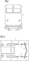
- Fig.1 shows by way of example and schematically the end face of a rail vehicle with a sanding device.
- a view of the end face of a rail vehicle 1 is shown, which has a rail clearer 5 below the car body.
- Two air inlets 3 are arranged in this rail clearer 5, each opening into a tubular air duct 2 and through which the air flow caused by the movement of the rail vehicle 1 is partially guided into the air ducts 2.
- the air flow guided in this way is guided through the tubular air ducts 2 in front of the wheels 4.
- a lane clearer 5 is particularly suitable for connecting an air inlet 3.
- a Air inlet 3 can also be arranged at a different position on the end face of a rail vehicle 1.
- Fig. 2 shows an example and schematically the underside of a rail vehicle with a sanding device. It is the underside of the rail vehicle 1 Fig.1 shown. In this view, the structure and function of the desanding device can be seen more clearly.
- the air flow 6 through the tubular air ducts 2 emerges at the end of the air ducts 2, in front of the respectively assigned wheel 4. This exiting air has a higher pressure than the surrounding still air, which removes the sand adhering to the tracks.
- the exact design of the openings of the air ducts 2 or optional nozzles at the end of the air ducts 2 are not shown in this schematic diagram.
- Fig. 3 shows an example and schematically the underside of a rail vehicle with a sanding device by means of a tubular air duct with a narrowing cross section. It is the embodiment from Fig. 2 shown, wherein the tubular air duct 2 has a curved course with a narrowing cross section.
- FIG. 4 shows an example and schematically a rail vehicle with a desanding device from an air baffle in a side view.
- a side view of a rail vehicle 1 is shown in the front area, which is similar to that in FIGS Figs. 1 to 3
- the embodiment shown comprises a web clearer 5.
- a desanding device in the form of an air baffle 7 is arranged between the lane scraper 5 and the leading wheel 4.
- the air baffle 7 is by means of a fastening 8 releasably attached to the car body of the rail vehicle 1.
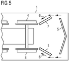
- Fig. 5 shows an example and schematically the underside of a rail vehicle with a desanding device made of an air baffle. It is the underside of the rail vehicle 1 Fig. 4 shown.
- the arrangement of the air guide plates 7 angled to the longitudinal axis of the rail vehicle 1 can be seen, which leads to an air flow 6 oriented transversely to the direction of travel directly in front of the wheels 4.
- the air baffles 7 are angled in such a way that the sending air flow 6 is caused by the negative pressure arising on the air baffle 7.
Landscapes
- Engineering & Computer Science (AREA)
- Architecture (AREA)
- Civil Engineering (AREA)
- Structural Engineering (AREA)
- Mechanical Engineering (AREA)
- Physics & Mathematics (AREA)
- Plasma & Fusion (AREA)
- Cleaning Of Streets, Tracks, Or Beaches (AREA)
- Cooling, Air Intake And Gas Exhaust, And Fuel Tank Arrangements In Propulsion Units (AREA)
Description
- Die Erfindung betrifft eine Entsandungseinrichtung für ein Schienenfahrzeug
- Ablagerungen von Sand auf Gleisen können für den Bahnbetrieb hinderlich sein. Insbesondere in Wüstengebieten können Gleise mit Sand verweht sein, was eine aufwendige Entfernung des Sandes erforderlich macht, da zu große Sandmengen auch zu Entgleisungen führen können. Dazu werden Sandräummaschinen eingesetzt, die an Kraftfahrzeugen angeordnet sind und welche den Sand beispielsweise mittels einer Sandfrässchleuder entfernen. Diese Maschinen können auch an der Stirnseite eines Schienenfahrzeugs angeordnet sein, welches die Strecke langsam befährt. Die bekannten Sandräumverfahren weisen jedoch einen Nachteil auf, da sie kleine Sandablagerungen am Schienenkopf nicht zu entfernen vermögen. Diese kleinen Sandablagerungen, welche für die Fahrsicherheit keine Einschränkung darstellen rufen jedoch einen massiv erhöhten Verschleiß an den Schienenfahrzeugrädern hervor. So ist das typische Intervall zwischen zwei Reprofilierungen (Nachbearbeitung des Radprofils) von 150.000km bei Fahrten in Wüstengebieten auf ca. 30.000km reduziert. Besonders nachteilig ist, dass diese minimalen Sandablagerungen durch Wind kontinuierlich neu geschaffen werden und eine Reinigungsfahrt zur Entfernung dieser minimalen Sandablagerungen mit einer Sandräummaschine sowohl unwirtschaftlich als auch erfolglos wäre. Es liegt nahe, daher die Schienenfahrzeuge selbst mit einer Einrichtung zur Entfernung geringer Sandablagerungen von den Gleisen auszustatten. Dadurch kann das Problem des kontinuierlich neu auf die Gleise eingebrachten Sandes gelöst werden, da eben das Schienenfahrzeug selbst diese Ablagerungen unmittelbar und während der Fahrt entfernt. Dazu können beispielsweise Bürsten eingesetzt werden, welche vor der führenden Achse angeordnet sind. Eine weitere Möglichkeit der Sandentfernung besteht durch das Ausblasen von im Fahrzeug erzeugter Druckluft. Alle diese Verfahren bedingen große Änderungen an dem Fahrzeug und rufen sowohl einen erhöhten Wartungsaufwand als auch einen erhöhten Energieverbrauch hervor.
US 2016/060833 A1 beschreibt ein Schienenfahrzeug nach dem Oberbegriff des Anspruchs 1. - Der Erfindung liegt daher die Aufgabe zugrunde, eine Entsandungseinrichtung für ein Schienenfahrzeug anzugeben, welche wartungs- und verschleißfrei ist und welche keinerlei Anschlüsse zu elektrischen oder pneumatischen Systemen des Schienenfahrzeugs erfordert.
- Die Aufgabe wird durch eine Entsandungseinrichtung mit den Merkmalen des Anspruchs 1 gelöst. Vorteilhafte Ausgestaltungen sind Gegenstand untergeordneter Ansprüche.
- Dem Grundgedanken der Erfindung nach wird eine Entsandungseinrichtung für ein Schienenfahrzeug aufgebaut, welche mindestens eine Luftleiteinrichtung mit Befestigungsmitteln zur Anordnung der Luftleiteinrichtung an dem Schienenfahrzeug umfasst, wobei die mindestens eine Luftleiteinrichtung so ausgebildet ist, dass die durch die Bewegung des Schienenfahrzeugs hervorgerufene Luftströmung an eine Position unmittelbar vor die Räder einer in Fahrtrichtung führenden Achse des Schienenfahrzeugs geleitet wird.
- Dadurch ist der Vorteil erzielbar, den am Schienenkopf anhaftenden Sand entfernen zu können und ein Zermahlen dieses Sandes durch die Räder des Schienenfahrzeugs verhindern zu können. Solcherart wird der Verschleiß der Räder verringert. Ein weiterer wesentlicher Vorteil der Erfindung liegt darin, dass die Entsandungseinrichtung keinerlei bewegte Teile oder Bürsten aufweist und auch keinerlei Anschlüsse zu elektrischen oder pneumatischen Systemen des Schienenfahrzeugs erfordert. Weiters kann eine erfindungsgemäße Entsandungseinrichtung bei bestehenden Fahrzeugen nachgerüstet werden.
- Die Erfindung sieht vor, dass die unmittelbar vor die Räder einer in Fahrtrichtung führenden Achse des Schienenfahrzeugs geleitete Luftströmung eine horizontale Geschwindigkeitskomponente normal zur Bewegungsrichtung des Schienenfahrzeugs umfasst. Dies wird durch eine Führung des Luftstroms in eine entsprechende Richtung durch die Luftleiteinrichtung gewährleistet. Dabei ist der Winkel der Luftströmung in Bezug auf das Gleis so zu wählen, dass der Sand die Gleisoberfläche verläßt bevor das Rad die betreffende Stelle berührt.
- Die Luftleiteinrichtung kann auf mehrere Arten ausgebildet sein, wobei entsprechend einer ersten nicht beanspruchten Variante die Luftleiteinrichtung als Rohr ausgebildet ist. Dieses Rohr erstreckt sich von der Stirnseite des Schienenfahrzeugs bis zu einer Position unmittelbar vor dem führenden Rad. Das dem Rad zugewandten Ende des Rohres kann mit einer den Rohrquerschnitt verengenden Düse ausgestattet sein, wodurch die Ausströmungseigenschaften, insb. der Auftreffpunkt und Auftreffwinkel der Luftströmung auf das Gleis gut vorgebbar sind.
- Dabei kann es besonders vorteilhaft sein, die Luftleiteinrichtung als Rohr mit in Bewegungsrichtung der Luftströmung verkleinerndem Querschnitt auszuführen.
- Solcherart kann die pro Zeiteinheit durch die Luftleiteinrichtung geführte Luftmenge gesteigert werden und der Ausblasdruck und somit die Reinigungswirkung erhöht werden.
- Ferner sieht die Erfindung vor, die Luftleiteinrichtung als Luftleitblech auszuführen. Dazu ist unmittelbar vor dem führenden Rad ein Luftleitblech anzuordnen, welches entsprechende Befestigungsmittel für die Befestigung an dem Wagenkasten des Schienenfahrzeugs umfasst. Dieses Luftleitblech besteht im einfachsten Fall aus einem zur Längsachse des Schienenfahrzeugs gewinkelten Blech, welches die Luftströmung vor dem führenden Rad gezielt lenkt, sodass am Schienenkopf haftender Sand von dieser gelenkten Luftströmung mitgenommen wird und nicht mehr durch das Rad zermahlen wird.
- Das Luftleitblech kann in einfacher Ausführung als blechförmiger Bauteil ausgeführt werden, wobei zur optimalen Anpassung der Luftströmung Ausnehmungen (Bohrungen) in das Luftleitblech eingebracht werden können. Diese Bohrungen verändern die Druck- und Strömungsverhältnisse, sodass eine exakte Anpassung an ein konkretes Schienenfahrzeug unter Berücksichtigung der häufigst gefahrenen Geschwindigkeit möglich ist.
- Das angeströmte Luftleitblech weist dabei eine Überdruck- und eine Unterdruckseite auf, welche sich aus der Anordnung in einer bewegten Luftmasse ergibt. Es können sowohl der aus der Strömung entstehende Überdruck (von der angeströmten Seite des Luftleitblechs) zur Entsandung eingesetzt werden als auch der Unterdruck an der nichtangeströmten Seite. Zweiteres ist in praktischen Ausführungen der Erfindung vorteilhaft, da dadurch das Luftbleitblech näher der Fahrzeuglängsachse angeordnet werden kann und der Bauraum für das Luftleitblech keinesfalls aus dem Lichtraumprofil des Fahrzeugs ragen darf. Das Luftleitblech kann auch, ähnlich wie die Tragfläche eines Flugzeugs mit einem strömungsgünstigen Profil ausgestattet sein, was eine besonders exakte Leitung der Luftströmung erlaubt, den Bauaufwand für ein Luftleitblech jedoch erhöht.
- Eine weitere Ausführungsform der Erfindung sieht vor, Einbauten am Untergestell eines Schienenfahrzeugs mit aerodynamischen Eigenschaften auszustatten, welche eine Luftströmung unmittelbar vor die Räder einer in Fahrtrichtung führenden Achse des Schienenfahrzeugs leitet. Dies kann beispielsweise durch entsprechend geformte Unterflurcontainer oder ähnliche Einrichtungen erfolgen.
- Es sind typischerweise je führendem Rad eines Schienenfahrzeugs eine Luftleiteinrichtung vorzusehen. Bei längeren Fahrzeugen, bzw. Zugzusammenstellungen kann es vorteilhaft sein, mehrere Entsandungseinrichtungen je Zugzusammenstellung vorzusehen.
- Es zeigen beispielhaft:
-
Fig.1 Schienenfahrzeug mit Entsandungseinrichtung mittels rohrförmiger Luftführung, Stirnseite (nicht beansprucht). -
Fig.2 Schienenfahrzeug mit Entsandungseinrichtung mittels rohrförmiger Luftführung, Unterseite (nicht beansprucht) -
Fig.3 Schienenfahrzeug mit Entsandungseinrichtung mittels rohrförmiger Luftführung mit verengendem Querschnitt, Unterseite (nicht beansprucht). -
Fig.4 Schienenfahrzeug mit Entsandungseinrichtung mittels Luftleitblech, Seitenansicht. -
Fig.5 Schienenfahrzeug mit Entsandungseinrichtung mittels Luftleitblech, Unterseite. -
Fig.1 zeigt beispielhaft und schematisch die Stirnseite eines Schienenfahrzeugs mit einer Entsandungseinrichtung. Es ist eine Ansicht auf die Stirnseite eines Schienenfahrzeugs 1 dargestellt, welches unterhalb des Wagenkastens einen Bahnräumer 5 aufweist. In diesem Bahnräumer 5 sind zwei Lufteinlässe 3 angeordnet, welche in je eine rohrförmige Luftführung 2 münden und durch welche die durch die Bewegung des Schienenfahrzeugs 1 hervorgerufene Luftströmung teilweise in die Luftführungen 2 geleitet wird. Die solcherart geleitete Luftströmung wird durch die rohrförmigen Luftführungen 2 vor die Räder 4 geleitet. Ein Bahnräumer 5 ist besonders gut für die Anbindung eines Lufteinlasses 3 geeignet. Für Fahrzeuge ohne Bahnräumer 5 oder wenn eine Anordnung am Bahnräumer 5 nicht gewünscht ist, kann ein Lufteinlass 3 auch an anderer Position an der Stirnseite eines Schienenfahrzeugs 1 angeordnet werden. -
Fig.2 zeigt beispielhaft und schematisch die Unterseite eines Schienenfahrzeugs mit einer Entsandungseinrichtung. Es ist die Unterseite des Schienenfahrzeugs 1 ausFig.1 dargestellt. In dieser Ansicht sind der Aufbau und die Funktion der Entsandungseinrichtung deutlicher erkennbar. Die Luftströmung 6 durch die rohrförmigen Luftführungen 2 tritt am Ende der Luftführungen 2, vor dem jeweils zugeordneten Rad 4 aus. Diese austretende Luft weist einen höheren Druck als die umgebende ruhende Luft auf, wodurch der auf den Gleisen haftende Sand entfernt wird. Die exakte Ausführung der Öffnungen der Luftführungen 2 oder optionale Düsen am Ende der Luftführungen 2 sind in dieser Prinzipskizze nicht dargestellt. -
Fig.3 zeigt beispielhaft und schematisch die Unterseite eines Schienenfahrzeugs mit Entsandungseinrichtung mittels rohrförmiger Luftführung mit verengendem Querschnitt. Es ist das Ausführungsbeispiel ausFig. 2 dargestellt, wobei die rohrförmige Luftführung 2 einen gebogenen Verlauf mit verengendem Querschnitt aufweist. -
Fig.4 zeigt beispielhaft und schematisch ein Schienenfahrzeug mit einer Entsandungseinrichtung aus einem Luftleitblech in einer Seitenansicht. Es ist eine Seitenansicht auf ein Schienenfahrzeug 1 im Stirnbereich dargestellt, welches ähnlich wie bei dem in denFig. 1 bis 3 gezeigten Ausführungsbeispiel einen Bahnräumer 5 umfasst. Zwischen dem Bahnräumer 5 und dem führenden Rad 4 ist eine Entsandungseinrichtung in Form eines Luftleitblechs 7 angeordnet. Das Luftleitblech 7 ist mittels einer Befestigung 8 an dem Wagenkasten des Schienenfahrzeugs 1 lösbar befestigt. -
Fig.5 zeigt beispielhaft und schematisch die Unterseite eines Schienenfahrzeugs mit einer Entsandungseinrichtung aus einem Luftleitblech. Es ist die Unterseite des Schienenfahrzeugs 1 ausFig. 4 dargestellt. Dabei ist die zur Längsachse des Schienenfahrzeugs 1 gewinkelte Anordnung der Luftleitbleche 7 erkennbar, welche zu einer quer zur Fahrtrichtung orientierten Luftströmung 6 unmittelbar vor den Rädern 4 führt. In gezeigtem Ausführungsbeispiel sind die Luftleitbleche 7 so gewinkelt, dass die entsandende Luftströmung 6 durch den am Luftleitblech 7 entstehenden Unterdruck hervorgerufen wird. -
- 1
- Schienenfahrzeug
- 2
- Rohrförmige Luftführung
- 3
- Lufteinlaß
- 4
- Rad
- 5
- Bahnräumer
- 6
- Luftströmung
- 7
- Luftleitblech
- 8
- Befestigung
Claims (2)
- Schienenfahrzeug (1), umfassend eine Entsandungseinrichtung mit mindestens einer Luftleiteinrichtung (2, 7) zur Bewirkung einer Luftströmung, welche Befestigungsmittel (8) zur Anordnung der Luftleiteinrichtung an dem Schienenfahrzeug (1) umfasst, wobei die Luftleiteinrichtung (7) als Luftleitblech ausgeführt ist, dadurch gekennzeichnet, dass die mindestens eine Luftleiteinrichtung (2, 7) so ausgebildet ist, dass die durch die Bewegung des Schienenfahrzeugs (1) hervorgerufene Luftströmung (6) an eine Position unmittelbar vor die Räder (4) einer in Fahrtrichtung führenden Achse des Schienenfahrzeugs (1) geleitet wird, und wobei die bewirkte Luftströmung (6) eine horizontale Geschwindigkeitskomponente normal zur Bewegungsrichtung des Schienenfahrzeugs (1) aufweist, wobei das Luftleitblech zur Längsachse des Schienenfahrzeugs (1) gewinkelt angeordnet ist.
- Schienenfahrzeug (1) nach Anspruch 1,
dadurch gekennzeichnet, dass das Luftleitblech (7) mit Ausnehmungen ausgestattet ist.
Applications Claiming Priority (2)
| Application Number | Priority Date | Filing Date | Title |
|---|---|---|---|
| ATA50357/2016A AT518603B1 (de) | 2016-04-22 | 2016-04-22 | Entsandungseinrichtung |
| PCT/EP2017/059110 WO2017182428A1 (de) | 2016-04-22 | 2017-04-18 | Entsandungseinrichtung |
Publications (2)
| Publication Number | Publication Date |
|---|---|
| EP3420139A1 EP3420139A1 (de) | 2019-01-02 |
| EP3420139B1 true EP3420139B1 (de) | 2020-10-07 |
Family
ID=58632955
Family Applications (1)
| Application Number | Title | Priority Date | Filing Date |
|---|---|---|---|
| EP17719528.6A Active EP3420139B1 (de) | 2016-04-22 | 2017-04-18 | Entsandungseinrichtung |
Country Status (4)
| Country | Link |
|---|---|
| EP (1) | EP3420139B1 (de) |
| AT (1) | AT518603B1 (de) |
| ES (1) | ES2835077T3 (de) |
| WO (1) | WO2017182428A1 (de) |
Families Citing this family (3)
| Publication number | Priority date | Publication date | Assignee | Title |
|---|---|---|---|---|
| US10167600B2 (en) * | 2013-10-01 | 2019-01-01 | Volvo Truck Corporation | Particle removing arrangement for an electric vehicle |
| CN108867535B (zh) * | 2018-06-11 | 2019-12-03 | 诸暨东白电农农业开发有限公司 | 一种用于沙漠路段铁轨的清沙装置 |
| CN109837861B (zh) * | 2019-03-21 | 2020-11-10 | 石家庄铁道大学 | 斗轮式轨道除沙车 |
Family Cites Families (5)
| Publication number | Priority date | Publication date | Assignee | Title |
|---|---|---|---|---|
| US521544A (en) * | 1894-06-19 | Snow-cleaning attachment for locomotive-engines | ||
| US2374312A (en) * | 1944-02-25 | 1945-04-24 | Tackett Elijah | Railroad track cleaner |
| JPS5024494B2 (de) * | 1972-06-15 | 1975-08-15 | ||
| US10167600B2 (en) * | 2013-10-01 | 2019-01-01 | Volvo Truck Corporation | Particle removing arrangement for an electric vehicle |
| US9631332B2 (en) * | 2014-08-28 | 2017-04-25 | Electro-Motive Diesel, Inc. | Movable sand plow for locomotive |
-
2016
- 2016-04-22 AT ATA50357/2016A patent/AT518603B1/de not_active IP Right Cessation
-
2017
- 2017-04-18 EP EP17719528.6A patent/EP3420139B1/de active Active
- 2017-04-18 ES ES17719528T patent/ES2835077T3/es active Active
- 2017-04-18 WO PCT/EP2017/059110 patent/WO2017182428A1/de not_active Ceased
Non-Patent Citations (1)
| Title |
|---|
| None * |
Also Published As
| Publication number | Publication date |
|---|---|
| AT518603A1 (de) | 2017-11-15 |
| ES2835077T3 (es) | 2021-06-21 |
| AT518603B1 (de) | 2018-02-15 |
| EP3420139A1 (de) | 2019-01-02 |
| WO2017182428A1 (de) | 2017-10-26 |
Similar Documents
| Publication | Publication Date | Title |
|---|---|---|
| EP3365216B1 (de) | Pneumatische trittplattenreinigung | |
| EP3371028B1 (de) | Schienenfahrzeug mit einem verkleideten drehgestell | |
| EP3420139B1 (de) | Entsandungseinrichtung | |
| DE19728265C2 (de) | Vorrichtung zur Belüftung eines Aggregates an einem Fahrzeug | |
| DE102017101850A1 (de) | Installationsanordnung und Verfahren zur automatisierten Reinigung von Lamellenwärmetauschern | |
| DE3245410A1 (de) | Spoileranordnung | |
| DE102016103265A1 (de) | Trittvorrichtung für ein Fahrzeug und Verfahren zum Betrieb dafür | |
| EP2692585A1 (de) | Kameraaußengehäuse für den Einsatz in der Verkehrstechnik | |
| DE102019100301A1 (de) | Tunnelreinigungszug | |
| EP3386831B1 (de) | Eisenbahn-triebfahrzeug mit dachübergangselement | |
| DE102020120183A1 (de) | Schienenfahrzeug mit Schienenräumer | |
| EP0202483B1 (de) | Bauelement für Übergangsschutzeinrichtungen für gelenkig miteinander zu kuppelnde Fahrzeuge, insbesondere Schienenfahrzeuge | |
| DE692776C (de) | Selbsttaetiger Foerderwagenumlauf | |
| DE19742102C1 (de) | Vorlaufsperre für schienengebundene Fahrzeuge | |
| EP3284866B1 (de) | Räumfahrzeug mit einer koppelbaren kehrblasanordnung | |
| EP0879919A2 (de) | Vorrichtung zur Reinigung von Tunnelwänden und/oder Tunneldecken | |
| DE2640629A1 (de) | Schneepflug | |
| EP2599682B1 (de) | Schutzeinrichtung für eine Komponente an einer Unterseite eines Schienenfahrzeugs | |
| DE2942809A1 (de) | Sandungsvorrichtung fuer fahrzeuge | |
| EP1659049B1 (de) | Bug für einen Personenkraftwagen | |
| DE158C (de) | Radflantschen-Benetzer | |
| DE325643C (de) | Fuehrungseinrichtung fuer Eisenbahnwagen an Ablaufbergen | |
| AT502533A1 (de) | Verfahren und vorrichtung zum abbremsen von flugzeugen | |
| EP3247607B1 (de) | Aerodynamisches hilfsmittel für ein schienenfahrzeug | |
| DE102021214556A1 (de) | Schienenfahrzeug |
Legal Events
| Date | Code | Title | Description |
|---|---|---|---|
| STAA | Information on the status of an ep patent application or granted ep patent |
Free format text: STATUS: UNKNOWN |
|
| STAA | Information on the status of an ep patent application or granted ep patent |
Free format text: STATUS: THE INTERNATIONAL PUBLICATION HAS BEEN MADE |
|
| PUAI | Public reference made under article 153(3) epc to a published international application that has entered the european phase |
Free format text: ORIGINAL CODE: 0009012 |
|
| STAA | Information on the status of an ep patent application or granted ep patent |
Free format text: STATUS: REQUEST FOR EXAMINATION WAS MADE |
|
| 17P | Request for examination filed |
Effective date: 20180927 |
|
| AK | Designated contracting states |
Kind code of ref document: A1 Designated state(s): AL AT BE BG CH CY CZ DE DK EE ES FI FR GB GR HR HU IE IS IT LI LT LU LV MC MK MT NL NO PL PT RO RS SE SI SK SM TR |
|
| AX | Request for extension of the european patent |
Extension state: BA ME |
|
| RAP1 | Party data changed (applicant data changed or rights of an application transferred) |
Owner name: SIEMENS MOBILITY GMBH |
|
| DAV | Request for validation of the european patent (deleted) | ||
| DAX | Request for extension of the european patent (deleted) | ||
| STAA | Information on the status of an ep patent application or granted ep patent |
Free format text: STATUS: EXAMINATION IS IN PROGRESS |
|
| 17Q | First examination report despatched |
Effective date: 20190925 |
|
| RAP1 | Party data changed (applicant data changed or rights of an application transferred) |
Owner name: SIEMENS MOBILITY AUSTRIA GMBH |
|
| GRAP | Despatch of communication of intention to grant a patent |
Free format text: ORIGINAL CODE: EPIDOSNIGR1 |
|
| STAA | Information on the status of an ep patent application or granted ep patent |
Free format text: STATUS: GRANT OF PATENT IS INTENDED |
|
| INTG | Intention to grant announced |
Effective date: 20200605 |
|
| GRAS | Grant fee paid |
Free format text: ORIGINAL CODE: EPIDOSNIGR3 |
|
| GRAA | (expected) grant |
Free format text: ORIGINAL CODE: 0009210 |
|
| STAA | Information on the status of an ep patent application or granted ep patent |
Free format text: STATUS: THE PATENT HAS BEEN GRANTED |
|
| AK | Designated contracting states |
Kind code of ref document: B1 Designated state(s): AL AT BE BG CH CY CZ DE DK EE ES FI FR GB GR HR HU IE IS IT LI LT LU LV MC MK MT NL NO PL PT RO RS SE SI SK SM TR |
|
| REG | Reference to a national code |
Ref country code: GB Ref legal event code: FG4D Free format text: NOT ENGLISH |
|
| REG | Reference to a national code |
Ref country code: CH Ref legal event code: EP Ref country code: AT Ref legal event code: REF Ref document number: 1321278 Country of ref document: AT Kind code of ref document: T Effective date: 20201015 |
|
| REG | Reference to a national code |
Ref country code: DE Ref legal event code: R096 Ref document number: 502017007612 Country of ref document: DE |
|
| REG | Reference to a national code |
Ref country code: IE Ref legal event code: FG4D Free format text: LANGUAGE OF EP DOCUMENT: GERMAN |
|
| REG | Reference to a national code |
Ref country code: CH Ref legal event code: NV Representative=s name: SIEMENS SCHWEIZ AG, CH |
|
| REG | Reference to a national code |
Ref country code: NL Ref legal event code: MP Effective date: 20201007 |
|
| PG25 | Lapsed in a contracting state [announced via postgrant information from national office to epo] |
Ref country code: NO Free format text: LAPSE BECAUSE OF FAILURE TO SUBMIT A TRANSLATION OF THE DESCRIPTION OR TO PAY THE FEE WITHIN THE PRESCRIBED TIME-LIMIT Effective date: 20210107 Ref country code: PT Free format text: LAPSE BECAUSE OF FAILURE TO SUBMIT A TRANSLATION OF THE DESCRIPTION OR TO PAY THE FEE WITHIN THE PRESCRIBED TIME-LIMIT Effective date: 20210208 Ref country code: RS Free format text: LAPSE BECAUSE OF FAILURE TO SUBMIT A TRANSLATION OF THE DESCRIPTION OR TO PAY THE FEE WITHIN THE PRESCRIBED TIME-LIMIT Effective date: 20201007 Ref country code: FI Free format text: LAPSE BECAUSE OF FAILURE TO SUBMIT A TRANSLATION OF THE DESCRIPTION OR TO PAY THE FEE WITHIN THE PRESCRIBED TIME-LIMIT Effective date: 20201007 Ref country code: GR Free format text: LAPSE BECAUSE OF FAILURE TO SUBMIT A TRANSLATION OF THE DESCRIPTION OR TO PAY THE FEE WITHIN THE PRESCRIBED TIME-LIMIT Effective date: 20210108 |
|
| REG | Reference to a national code |
Ref country code: LT Ref legal event code: MG4D |
|
| PG25 | Lapsed in a contracting state [announced via postgrant information from national office to epo] |
Ref country code: SE Free format text: LAPSE BECAUSE OF FAILURE TO SUBMIT A TRANSLATION OF THE DESCRIPTION OR TO PAY THE FEE WITHIN THE PRESCRIBED TIME-LIMIT Effective date: 20201007 Ref country code: IS Free format text: LAPSE BECAUSE OF FAILURE TO SUBMIT A TRANSLATION OF THE DESCRIPTION OR TO PAY THE FEE WITHIN THE PRESCRIBED TIME-LIMIT Effective date: 20210207 Ref country code: PL Free format text: LAPSE BECAUSE OF FAILURE TO SUBMIT A TRANSLATION OF THE DESCRIPTION OR TO PAY THE FEE WITHIN THE PRESCRIBED TIME-LIMIT Effective date: 20201007 Ref country code: LV Free format text: LAPSE BECAUSE OF FAILURE TO SUBMIT A TRANSLATION OF THE DESCRIPTION OR TO PAY THE FEE WITHIN THE PRESCRIBED TIME-LIMIT Effective date: 20201007 Ref country code: BG Free format text: LAPSE BECAUSE OF FAILURE TO SUBMIT A TRANSLATION OF THE DESCRIPTION OR TO PAY THE FEE WITHIN THE PRESCRIBED TIME-LIMIT Effective date: 20210107 |
|
| REG | Reference to a national code |
Ref country code: ES Ref legal event code: FG2A Ref document number: 2835077 Country of ref document: ES Kind code of ref document: T3 Effective date: 20210621 |
|
| PG25 | Lapsed in a contracting state [announced via postgrant information from national office to epo] |
Ref country code: NL Free format text: LAPSE BECAUSE OF FAILURE TO SUBMIT A TRANSLATION OF THE DESCRIPTION OR TO PAY THE FEE WITHIN THE PRESCRIBED TIME-LIMIT Effective date: 20201007 Ref country code: HR Free format text: LAPSE BECAUSE OF FAILURE TO SUBMIT A TRANSLATION OF THE DESCRIPTION OR TO PAY THE FEE WITHIN THE PRESCRIBED TIME-LIMIT Effective date: 20201007 |
|
| REG | Reference to a national code |
Ref country code: DE Ref legal event code: R097 Ref document number: 502017007612 Country of ref document: DE |
|
| PG25 | Lapsed in a contracting state [announced via postgrant information from national office to epo] |
Ref country code: SM Free format text: LAPSE BECAUSE OF FAILURE TO SUBMIT A TRANSLATION OF THE DESCRIPTION OR TO PAY THE FEE WITHIN THE PRESCRIBED TIME-LIMIT Effective date: 20201007 Ref country code: LT Free format text: LAPSE BECAUSE OF FAILURE TO SUBMIT A TRANSLATION OF THE DESCRIPTION OR TO PAY THE FEE WITHIN THE PRESCRIBED TIME-LIMIT Effective date: 20201007 Ref country code: EE Free format text: LAPSE BECAUSE OF FAILURE TO SUBMIT A TRANSLATION OF THE DESCRIPTION OR TO PAY THE FEE WITHIN THE PRESCRIBED TIME-LIMIT Effective date: 20201007 Ref country code: CZ Free format text: LAPSE BECAUSE OF FAILURE TO SUBMIT A TRANSLATION OF THE DESCRIPTION OR TO PAY THE FEE WITHIN THE PRESCRIBED TIME-LIMIT Effective date: 20201007 Ref country code: SK Free format text: LAPSE BECAUSE OF FAILURE TO SUBMIT A TRANSLATION OF THE DESCRIPTION OR TO PAY THE FEE WITHIN THE PRESCRIBED TIME-LIMIT Effective date: 20201007 Ref country code: RO Free format text: LAPSE BECAUSE OF FAILURE TO SUBMIT A TRANSLATION OF THE DESCRIPTION OR TO PAY THE FEE WITHIN THE PRESCRIBED TIME-LIMIT Effective date: 20201007 |
|
| PLBE | No opposition filed within time limit |
Free format text: ORIGINAL CODE: 0009261 |
|
| STAA | Information on the status of an ep patent application or granted ep patent |
Free format text: STATUS: NO OPPOSITION FILED WITHIN TIME LIMIT |
|
| PG25 | Lapsed in a contracting state [announced via postgrant information from national office to epo] |
Ref country code: DK Free format text: LAPSE BECAUSE OF FAILURE TO SUBMIT A TRANSLATION OF THE DESCRIPTION OR TO PAY THE FEE WITHIN THE PRESCRIBED TIME-LIMIT Effective date: 20201007 |
|
| 26N | No opposition filed |
Effective date: 20210708 |
|
| PG25 | Lapsed in a contracting state [announced via postgrant information from national office to epo] |
Ref country code: IT Free format text: LAPSE BECAUSE OF FAILURE TO SUBMIT A TRANSLATION OF THE DESCRIPTION OR TO PAY THE FEE WITHIN THE PRESCRIBED TIME-LIMIT Effective date: 20201007 Ref country code: AL Free format text: LAPSE BECAUSE OF FAILURE TO SUBMIT A TRANSLATION OF THE DESCRIPTION OR TO PAY THE FEE WITHIN THE PRESCRIBED TIME-LIMIT Effective date: 20201007 |
|
| PG25 | Lapsed in a contracting state [announced via postgrant information from national office to epo] |
Ref country code: SI Free format text: LAPSE BECAUSE OF FAILURE TO SUBMIT A TRANSLATION OF THE DESCRIPTION OR TO PAY THE FEE WITHIN THE PRESCRIBED TIME-LIMIT Effective date: 20201007 Ref country code: MC Free format text: LAPSE BECAUSE OF FAILURE TO SUBMIT A TRANSLATION OF THE DESCRIPTION OR TO PAY THE FEE WITHIN THE PRESCRIBED TIME-LIMIT Effective date: 20201007 |
|
| GBPC | Gb: european patent ceased through non-payment of renewal fee |
Effective date: 20210418 |
|
| PG25 | Lapsed in a contracting state [announced via postgrant information from national office to epo] |
Ref country code: LU Free format text: LAPSE BECAUSE OF NON-PAYMENT OF DUE FEES Effective date: 20210418 |
|
| REG | Reference to a national code |
Ref country code: BE Ref legal event code: MM Effective date: 20210430 |
|
| PG25 | Lapsed in a contracting state [announced via postgrant information from national office to epo] |
Ref country code: GB Free format text: LAPSE BECAUSE OF NON-PAYMENT OF DUE FEES Effective date: 20210418 |
|
| PG25 | Lapsed in a contracting state [announced via postgrant information from national office to epo] |
Ref country code: IE Free format text: LAPSE BECAUSE OF NON-PAYMENT OF DUE FEES Effective date: 20210418 |
|
| PG25 | Lapsed in a contracting state [announced via postgrant information from national office to epo] |
Ref country code: IS Free format text: LAPSE BECAUSE OF FAILURE TO SUBMIT A TRANSLATION OF THE DESCRIPTION OR TO PAY THE FEE WITHIN THE PRESCRIBED TIME-LIMIT Effective date: 20210207 |
|
| PG25 | Lapsed in a contracting state [announced via postgrant information from national office to epo] |
Ref country code: BE Free format text: LAPSE BECAUSE OF NON-PAYMENT OF DUE FEES Effective date: 20210430 |
|
| PG25 | Lapsed in a contracting state [announced via postgrant information from national office to epo] |
Ref country code: CY Free format text: LAPSE BECAUSE OF FAILURE TO SUBMIT A TRANSLATION OF THE DESCRIPTION OR TO PAY THE FEE WITHIN THE PRESCRIBED TIME-LIMIT Effective date: 20201007 |
|
| PG25 | Lapsed in a contracting state [announced via postgrant information from national office to epo] |
Ref country code: HU Free format text: LAPSE BECAUSE OF FAILURE TO SUBMIT A TRANSLATION OF THE DESCRIPTION OR TO PAY THE FEE WITHIN THE PRESCRIBED TIME-LIMIT; INVALID AB INITIO Effective date: 20170418 |
|
| PG25 | Lapsed in a contracting state [announced via postgrant information from national office to epo] |
Ref country code: MK Free format text: LAPSE BECAUSE OF FAILURE TO SUBMIT A TRANSLATION OF THE DESCRIPTION OR TO PAY THE FEE WITHIN THE PRESCRIBED TIME-LIMIT Effective date: 20201007 |
|
| PG25 | Lapsed in a contracting state [announced via postgrant information from national office to epo] |
Ref country code: MT Free format text: LAPSE BECAUSE OF FAILURE TO SUBMIT A TRANSLATION OF THE DESCRIPTION OR TO PAY THE FEE WITHIN THE PRESCRIBED TIME-LIMIT Effective date: 20201007 |
|
| PGFP | Annual fee paid to national office [announced via postgrant information from national office to epo] |
Ref country code: DE Payment date: 20250620 Year of fee payment: 9 |
|
| PGFP | Annual fee paid to national office [announced via postgrant information from national office to epo] |
Ref country code: FR Payment date: 20250411 Year of fee payment: 9 |
|
| PGFP | Annual fee paid to national office [announced via postgrant information from national office to epo] |
Ref country code: AT Payment date: 20250307 Year of fee payment: 9 |
|
| PGFP | Annual fee paid to national office [announced via postgrant information from national office to epo] |
Ref country code: ES Payment date: 20250721 Year of fee payment: 9 |
|
| PGFP | Annual fee paid to national office [announced via postgrant information from national office to epo] |
Ref country code: CH Payment date: 20250709 Year of fee payment: 9 |
|
| PG25 | Lapsed in a contracting state [announced via postgrant information from national office to epo] |
Ref country code: TR Free format text: LAPSE BECAUSE OF FAILURE TO SUBMIT A TRANSLATION OF THE DESCRIPTION OR TO PAY THE FEE WITHIN THE PRESCRIBED TIME-LIMIT Effective date: 20201007 |