EP0879008B1 - A toilet cover assembly - Google Patents
A toilet cover assembly Download PDFInfo
- Publication number
- EP0879008B1 EP0879008B1 EP97904348A EP97904348A EP0879008B1 EP 0879008 B1 EP0879008 B1 EP 0879008B1 EP 97904348 A EP97904348 A EP 97904348A EP 97904348 A EP97904348 A EP 97904348A EP 0879008 B1 EP0879008 B1 EP 0879008B1
- Authority
- EP
- European Patent Office
- Prior art keywords
- seat
- bracket
- cover
- hinge
- pin
- Prior art date
- Legal status (The legal status is an assumption and is not a legal conclusion. Google has not performed a legal analysis and makes no representation as to the accuracy of the status listed.)
- Expired - Lifetime
Links
Images


Classifications
-
- A—HUMAN NECESSITIES
- A47—FURNITURE; DOMESTIC ARTICLES OR APPLIANCES; COFFEE MILLS; SPICE MILLS; SUCTION CLEANERS IN GENERAL
- A47K—SANITARY EQUIPMENT NOT OTHERWISE PROVIDED FOR; TOILET ACCESSORIES
- A47K13/00—Seats or covers for all kinds of closets
- A47K13/12—Hinges
Definitions
- the invention relates to a toilet cover assembly
- a toilet cover assembly comprising a seat and a cover, each being pivotally connected with a bracket about a common axis by means of two interspaced hinges, said bracket comprising a single bracket member or two separate bracket members and being provided with fastening means for fastening the bracket to a toilet bowl said seat and said cover being pivotally interconnected by means of two interspaced hinges of the pin/bearing type, each comprising a hinge member fixedly secured to the seat and a hinge member fixedly secured to the cover, one of the hinge members provided with a protruding pin and the other hinge member provided with a bearing for receiving the pin, said toilet cover assembly further provided with means for releasably connecting the cover and the seat with the bracket, the connecting means being adapted to releasably connect the bracket with an immediately adjacent seat hinge member and an immediately adjacent cover hinge member respectively
- DE-C2-31 19 622 discloses a toilet cover assembly of the above type, in which the seat and the cover each is provided with two interspaced hinge bearings, the hinge bearings of the cover being slightly more interspaced than the hinge bearings of the seat.
- the bracket is provided with two hinge pins each displaceable between a position in which they engage each of the adjacent bearings and a position in which they disengage said bearings.
- the seat and the cover is not hingedly interconnected, when they are detached from the bracket.
- the hinge bearings of the seat and cover are to be accurately aligned with each other and with the two hinge pins, and at the same time the two hinge pins are to be moved into the engagement position with the hinge bear-ings. This is not a simple task for a single person.
- the object of the invention is to provide a toilet cover assembly of the above type facilitating the release and in particular the fastening of the seat and the cover to the bracket.
- the toilet cover assembly according to the invention is characterised in that said seat hinge members and cover hinge members are arranged such on the seat and the cover respectively that the hinge pins can be brought into and out of engagement with the hinge bearings by axial displacement of the seat relative to the cover when the seat and the cover are detached from the bracket.
- the seat and cover are easily attached to and detached from the bracket.
- the assembly of the seat and the cover can then be connected with the bracket without difficulty, the correct mutual position of the seat and the cover as stated ensured by the hinge connection.
- these are also hingedly interconnected as an assembly and when detached from the bracket the seat and cover can be separated by displacing them axially relative to each other such that the pins and bearings of the hinges are brought out of engagement with one another.
- the seat and the cover can advantageously be cleaned individually prior to being re-interconnected and attached to the bracket as an assembly.
- the toilet cover assembly is further advantageous in connection with embodiments comprising a damper for damping the movement of the seat and the cover from the raised position to the lowered position in that the damper advantageously may be easily arranged in the bracket or in the adjacent hinge member of the seat and the cover respectively.
- the seat from the cover are readily separated from each other and quickly interconnected as well as attached to and detached from the bracket.
- the seat and the cover can each comprise a hinge member provided with a pin and a hinge member provided with a bearing.
- the hinge pin members of the seat and the cover as well as the hinge bearing members thereof can be identically shaped so as to facilitate the production thereof.
- the hinge member of the seat as well as of the cover arranged immediately adjacent the bracket can be a hinge pin member, whereby the hinge pins extend outwardly in the direction away from the bracket and thus provide a large interspace between the hinge points.
- the hinge arrangement such that the hinge member of both the seat and the cover arranged immediately adjacent the bracket is a hinge bearing member.
- the connecting means for releasably connecting the seat and the cover with the bracket can comprise a pin arranged axially displaceably between the hinge member immediately adjacent the bracket of the seat and the cover, respectively and the bracket, said pin adapted for a displacement between an engagement position and a release position.
- the displaceable pin can be arranged axially displaceable relative to the hinge member of the seat and of the cover, respectively immediately adjacent the bracket and adapted for a displacement between an engagement position in which it engages a corresponding axial recess in the bracket and a release position in which it disengages said recess.
- each of the displaceable pins can advantageously be springloaded towards its engagement position.
- an activation means can be provided connected to each of the displaceable pins and adapted when activated in axial direction to advance the displaceable pin from the engagement position to the release position.
- the bracket can comprise a housing accommodating at least one shaft arranged pivotable about the hinge axis and provided with a damper means and shaft end portions facing the adjacent hinge members, the connecting means being adapted to releasably connect each of the shaft end portions with the adjacent hinge members.
- each of hinge members immediately adjacent the bracket can comprise a housing accommodating a shaft arranged pivotable about the hinge members and provided with a damping arrangement and a shaft end portion facing the bracket, whereby the connecting means are adapted to releasably connect the shaft end portions with the bracket.
- the damper means can comprise a vane arranged pivotally in a part-cylindrical cavity formed in the bracket housing and filled with a highly viscous fluid.
- the part-cylindrical cavity is formed in the said hinge members.
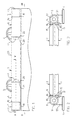
- the shown toilet cover assembly comprises a seat 1 and a cover 2 hingedly interconnected and pivotally connected with a bracket 3 provided with a housing 23 having two legs 54,55 with bases 4,5 by means of which the bracket 3 can be fastened to a toilet bowl in a known manner.
- the seat 1 and the cover 2 are hingedly interconnected by means of two interspaced hinges, each comprising a hinge member 6 provided with a pin and a hinge member 7 provided with a bearing.
- the hinge pin members 6 each comprises a cylindrical body 8 having an axially projecting pin 9, and a leg 10 extending substantially tangentially from the body 8 and ending in a mounting base 11.
- the hinge bearing members 7 each comprises a bearing 12 provided with a cylindrical cavity 13 adapted to receive the pin 9 of the hinge pin member 6 and a leg 14 extending substantially tangentially from the bearing and ending in a mounting base 15.
- the hinge pin members are identical as are the hinge bearing members.
- a hinge bearing member 7 is mounted on the rear edge 16 of the seat at one end and a hinge pin member 6 is mounted at the other end co-axially thereto, the pin 9 facing outwards.
- the mounting base 15 of the hinge bearing member 7 and the mounting base 11 of the hinge pin member are both countersunk in the rear edge 16 of the seat 1.
- a hinge pin member 6 with the pin 9 facing outwards is mounted at one end in the rear edge 17 of the cover 2 and a hinge bearing member 7 is mounted at the other end co-axially therewith.
- the mounting base 11 of the hinge pin member 6 and the mounting base 15 of the hinge bearing member 7 are both countersunk in the rear edge 17 of the cover.
- the hinge members 6,7 of the hinges are mounted such on the seat 1 and the cover 2 respectively that the pins 9 of the hinge pin members 6 can be brought into and out of engagement with the cavities 13 of the hinge bearing members 7 by an axial displacement of the cover 2 relative to the seat 1 when the seat 1 and the cover 2 are detached from the bracket 3.
- the hinge members are arranged such that when the pins 9 are in engagement with the bearings 12, a shoulder 18 between the body of the hinge pin members and the pin 9 essentially abuts an inwardly facing edge face 19 of the bearings 12.
- the distance between the inwardly facing end faces 20 of the body 8 of the hinge pin members 6 corresponds substantially to the distance between the end faces 21, 22 of the housing 23 facing away from each other.
- a shaft 25 is pivotally arranged in the interior of the housing 23 and prevented from axial displacement due to the abutment between an inner end face 27 thereof and the central wall 24 and the abutment between a shoulder 28 thereof and an inwardly extending projection 29 of the housing.
- An axial recess 31 having a cross-section not presenting rotation symmetry is provided in the outer end face 30 of the shaft, said face being substantially in the same plane as the end face 21 of the bracket housing 23.
- the shaft 25 is further provided with a radially annular projection 33 having an annular groove 34 accommodating a sealing ring 35 sealingly abutting the inner surface 36 of the bracket housing 23.
- a closed compartment is thus formed between the radial projection 33 and the central wall 34 and filled with a highly viscous fluid so as to form a damper.
- the damper further comprises a rib 37 extending radially inwards from the housing and substantially to the shaft 25, and a vane 38 extending radially outwards from the shaft and substantially to the inner surface 36 of the housing.
- the damper is provided with a one-way valve member (not shown) allowing for a flow of fluid between the two chambers formed by the vane 38 and the rib 37 when the shaft rotates in one direction and essentially preventing said flow of fluid when the shaft rotates in the opposite direction.
- a one-way valve member (not shown) allowing for a flow of fluid between the two chambers formed by the vane 38 and the rib 37 when the shaft rotates in one direction and essentially preventing said flow of fluid when the shaft rotates in the opposite direction.
- each of the hinge pin members 6 immediately adjacent the bracket 3 has a hollow interior.
- a substantially cup-shaped body 40 provided with a projecting pin 41 and having a cross section not presenting rotation symmetry is displaceably arranged in the interior of the hinge pin member 6 at the end thereof immediately adjacent the bracket 3.
- the body 40 is preloaded to adopt the engagement position with the recess 31 in the shaft 25 shown in Figs. 5 and 6 by means of a compression spring 42.
- a stop face 43 of the cup-shaped body 40 abuts an inner stop face 44 of the body 8 of the hinge pin member 6.
- the body 40 is prevented from rotating by an outer rib 45 on the cylindrical wall 46 of the body received in a corresponding groove 47 in the body 8 of the hinge pin member 6.
- the pin 41 of the body 40 can be moved from the engagement position shown in Figs. 5 and 6 to a release position in which it no longer extends beyond the inwardly facing end face 20 of the hinge pin member 6, whereby the hinge pin members 6 and the hinge bearing members 7 connected therewith and thus the seat and the cover can be detached from the bracket 3.
- the hinge pin member 6 is provided with an activation mechanism comprising an activation body 48 displaceably arranged in the interior of the hinge pin member 6 and an activation button 49 extending beyond the outer end face 50 of the pin 9 of the hinge pin member 6.
- the activation body 48 is provided with a rack 51 meshing with a gear wheel 52 pivotally arranged in the interior of the hinge pin member 6.
- the gear wheel 52 further engages a second rack 53 connected with the cup-shaped body 40 provided with the pin 41.
- the rack 51 rotates the gear wheel 52 which in turn displaces the second rack 53 in opposite direction of the rack 51 and thus advances the cup-shaped body 40 provided with the pin 41 toward the release position.
- the force of the compression spring causes the activation button 49 - when released - to revert to its initial position shown in Figs. 5 and 6 in which the pin 42 is in the engagement position.
- the bracket can thus comprise two separate bracket members, each of which being mounted on the toilet bowl.
- the separate bracket members can as the illustrated and described bracket 3 be arranged between the hinge members of the seat and the cover. They can, however, also be arranged at the outside of said members.
- one of the bracket members can be arranged between the hinge members and the second bracket member is arranged at the outside thereof.
Landscapes
- Health & Medical Sciences (AREA)
- Public Health (AREA)
- Toilet Supplies (AREA)
- Bidet-Like Cleaning Device And Other Flush Toilet Accessories (AREA)
Applications Claiming Priority (3)
| Application Number | Priority Date | Filing Date | Title |
|---|---|---|---|
| DK15396 | 1996-02-14 | ||
| DK015396A DK172266B1 (da) | 1996-02-14 | 1996-02-14 | Toiletafdækning |
| PCT/DK1997/000069 WO1997029674A1 (en) | 1996-02-14 | 1997-02-14 | A toilet cover assembly |
Publications (2)
| Publication Number | Publication Date |
|---|---|
| EP0879008A1 EP0879008A1 (en) | 1998-11-25 |
| EP0879008B1 true EP0879008B1 (en) | 2002-01-09 |
Family
ID=8090363
Family Applications (1)
| Application Number | Title | Priority Date | Filing Date |
|---|---|---|---|
| EP97904348A Expired - Lifetime EP0879008B1 (en) | 1996-02-14 | 1997-02-14 | A toilet cover assembly |
Country Status (7)
| Country | Link |
|---|---|
| US (1) | US6026520A (ja) |
| EP (1) | EP0879008B1 (ja) |
| JP (1) | JP2000504604A (ja) |
| AT (1) | ATE211630T1 (ja) |
| DE (1) | DE69709540T2 (ja) |
| DK (1) | DK172266B1 (ja) |
| WO (1) | WO1997029674A1 (ja) |
Families Citing this family (9)
| Publication number | Priority date | Publication date | Assignee | Title |
|---|---|---|---|---|
| DE10313394B4 (de) * | 2003-03-25 | 2005-02-24 | Pagette Sanitär Produktions- und Vertriebsgesellschaft mbH | Dämpfungseinrichtung |
| CN201759477U (zh) * | 2010-08-09 | 2011-03-16 | 彭东 | 拆装便捷的座便器盖板连接机构 |
| US8763168B2 (en) * | 2011-01-05 | 2014-07-01 | Zhongshan Meitu Plastic Ind. Co., Ltd. | Hinge assembly for toilet seat |
| CN106031604B (zh) * | 2015-03-10 | 2019-04-02 | 厦门优胜卫厨科技有限公司 | 一种马桶盖以及拆卸和安装马桶盖的上盖组件的方法 |
| WO2016146051A1 (zh) * | 2015-03-17 | 2016-09-22 | 厦门优胜卫厨科技有限公司 | 一种马桶盖以及拆卸和安装马桶盖的上盖组件的方法 |
| US10285546B2 (en) | 2017-02-13 | 2019-05-14 | Topseat International, Inc. | System and method for removably mounting toilet seat to toilet bowl |
| US20200029787A1 (en) * | 2017-03-28 | 2020-01-30 | Pionmedek Medical Technologies Co., Ltd. | Monitoring Apparatus, Monitoring Bougie, and Monitoring System |
| US10912431B2 (en) | 2018-07-10 | 2021-02-09 | Kohler Co. | Hinge assembly for toilet |
| US11564538B2 (en) | 2019-10-21 | 2023-01-31 | Bemis Manufacturing Company | Hinge post for toilet seat |
Family Cites Families (10)
| Publication number | Priority date | Publication date | Assignee | Title |
|---|---|---|---|---|
| US2431263A (en) * | 1945-01-18 | 1947-11-18 | Eric H Lundgren | Retaining means for toilet seat covers |
| US3032777A (en) * | 1960-02-08 | 1962-05-08 | American Radiator & Standard | Seat and cover structure |
| US3261029A (en) * | 1963-09-17 | 1966-07-19 | Beneke Corp | Toilet seat and cover assembly |
| US3590401A (en) * | 1970-02-10 | 1971-07-06 | Beatrice Foods Co | Toilet seat and hinge assembly |
| US4197596A (en) * | 1978-10-06 | 1980-04-15 | Giuseppe Fantetti | Cover for toilet bowls |
| DE3119622C2 (de) * | 1981-04-30 | 1984-11-08 | Roman Dietsche KG, 7868 Todtnau | WC-Sitz |
| US4680816A (en) * | 1984-09-19 | 1987-07-21 | Colombani Louie V | Multiple-ring toilet seat assembly and mounting means |
| NL9000961A (nl) * | 1990-04-23 | 1991-11-18 | Kleto Holland Bv | Bevestigingsmechanisme voor een toiletzitting. |
| US5255396A (en) * | 1991-07-26 | 1993-10-26 | Matsushita Electric Industrial Co., Ltd. | Sanitary cleaning device including a rotation deceleration device |
| US5279000A (en) * | 1992-11-12 | 1994-01-18 | Mercier William H | Automatic toilet seat lowering hinge assembly |
-
1996
- 1996-02-14 DK DK015396A patent/DK172266B1/da not_active IP Right Cessation
-
1997
- 1997-02-14 JP JP9528911A patent/JP2000504604A/ja active Pending
- 1997-02-14 US US09/101,323 patent/US6026520A/en not_active Expired - Lifetime
- 1997-02-14 EP EP97904348A patent/EP0879008B1/en not_active Expired - Lifetime
- 1997-02-14 AT AT97904348T patent/ATE211630T1/de active
- 1997-02-14 DE DE69709540T patent/DE69709540T2/de not_active Expired - Lifetime
- 1997-02-14 WO PCT/DK1997/000069 patent/WO1997029674A1/en active IP Right Grant
Also Published As
| Publication number | Publication date |
|---|---|
| DK172266B1 (da) | 1998-02-16 |
| WO1997029674A1 (en) | 1997-08-21 |
| EP0879008A1 (en) | 1998-11-25 |
| US6026520A (en) | 2000-02-22 |
| JP2000504604A (ja) | 2000-04-18 |
| DE69709540D1 (de) | 2002-02-14 |
| ATE211630T1 (de) | 2002-01-15 |
| DE69709540T2 (de) | 2002-08-01 |
| DK15396A (da) | 1997-08-15 |
Similar Documents
| Publication | Publication Date | Title |
|---|---|---|
| EP0879008B1 (en) | A toilet cover assembly | |
| ES2258998T3 (es) | Articulacion de asiento de wc. | |
| US4542558A (en) | Unhingeable door hinge joint having a hinge pin with a nonrotatable portion and a relatively rotatable portion | |
| JP3633697B2 (ja) | 自動ロック式の差動装置 | |
| RU2313638C2 (ru) | Узел соединительного пальца для сборок коронка зуба - держатель | |
| US7441309B2 (en) | Hinge structure of a case | |
| ES2442565T3 (es) | Bisagra o articulación para muebles con equipamiento | |
| JP4546063B2 (ja) | 超音波溶接されたヒンジ式ダンパ | |
| CA2475193C (en) | Damped armrest | |
| US3736701A (en) | Revolving door | |
| US3971099A (en) | Hinge assembly stop attachment | |
| GB2338037A (en) | Side shaft journal for a differential drive with an adapted jont component of a CV-jointed shaft | |
| JPH0349443B2 (ja) | ||
| JP4249808B2 (ja) | ロータリーダンパ及びそれを用いたリクライニング部材 | |
| KR930006509B1 (ko) | 회전밸브 조립체 및 그의 조립방법 | |
| JPS6164978A (ja) | 自動車ドアのための分離可能なドアヒンジ | |
| WO1997029673A1 (en) | A toilet cover assembly with damper | |
| US6561912B1 (en) | Drive shaft | |
| JP3431788B2 (ja) | 便座および便蓋のダンパユニット | |
| EP2152995B1 (en) | Hinge for automotive vehicle doors | |
| CN208755840U (zh) | 一种旋控快拆铰链及具有该铰链的马桶盖板 | |
| CN209863625U (zh) | 一种盖板快速拆装装置 | |
| WO1999063874A1 (en) | Toilet cover assembly with mechanical damper | |
| US6450552B1 (en) | Sanitary fixture, more particularly a wash-stand fixture | |
| MXPA98006520A (es) | Fijador de puerta constructivamente con una bisagra de puerta enganchable. |
Legal Events
| Date | Code | Title | Description |
|---|---|---|---|
| PUAI | Public reference made under article 153(3) epc to a published international application that has entered the european phase |
Free format text: ORIGINAL CODE: 0009012 |
|
| 17P | Request for examination filed |
Effective date: 19980701 |
|
| AK | Designated contracting states |
Kind code of ref document: A1 Designated state(s): AT BE DE GB IT NL |
|
| 17Q | First examination report despatched |
Effective date: 19991124 |
|
| GRAG | Despatch of communication of intention to grant |
Free format text: ORIGINAL CODE: EPIDOS AGRA |
|
| GRAG | Despatch of communication of intention to grant |
Free format text: ORIGINAL CODE: EPIDOS AGRA |
|
| GRAH | Despatch of communication of intention to grant a patent |
Free format text: ORIGINAL CODE: EPIDOS IGRA |
|
| GRAH | Despatch of communication of intention to grant a patent |
Free format text: ORIGINAL CODE: EPIDOS IGRA |
|
| GRAA | (expected) grant |
Free format text: ORIGINAL CODE: 0009210 |
|
| REG | Reference to a national code |
Ref country code: GB Ref legal event code: IF02 |
|
| AK | Designated contracting states |
Kind code of ref document: B1 Designated state(s): AT BE DE GB IT NL |
|
| REF | Corresponds to: |
Ref document number: 211630 Country of ref document: AT Date of ref document: 20020115 Kind code of ref document: T |
|
| REF | Corresponds to: |
Ref document number: 69709540 Country of ref document: DE Date of ref document: 20020214 |
|
| PLBE | No opposition filed within time limit |
Free format text: ORIGINAL CODE: 0009261 |
|
| STAA | Information on the status of an ep patent application or granted ep patent |
Free format text: STATUS: NO OPPOSITION FILED WITHIN TIME LIMIT |
|
| 26N | No opposition filed | ||
| PGFP | Annual fee paid to national office [announced via postgrant information from national office to epo] |
Ref country code: BE Payment date: 20060222 Year of fee payment: 10 |
|
| BERE | Be: lapsed |
Owner name: *PRESSALIT A/S Effective date: 20070228 |
|
| PG25 | Lapsed in a contracting state [announced via postgrant information from national office to epo] |
Ref country code: BE Free format text: LAPSE BECAUSE OF NON-PAYMENT OF DUE FEES Effective date: 20070228 |
|
| PGFP | Annual fee paid to national office [announced via postgrant information from national office to epo] |
Ref country code: DE Payment date: 20120222 Year of fee payment: 16 |
|
| PGFP | Annual fee paid to national office [announced via postgrant information from national office to epo] |
Ref country code: GB Payment date: 20120222 Year of fee payment: 16 Ref country code: IT Payment date: 20120227 Year of fee payment: 16 |
|
| PGFP | Annual fee paid to national office [announced via postgrant information from national office to epo] |
Ref country code: NL Payment date: 20120222 Year of fee payment: 16 |
|
| PGFP | Annual fee paid to national office [announced via postgrant information from national office to epo] |
Ref country code: AT Payment date: 20120221 Year of fee payment: 16 |
|
| REG | Reference to a national code |
Ref country code: NL Ref legal event code: V1 Effective date: 20130901 |
|
| REG | Reference to a national code |
Ref country code: AT Ref legal event code: MM01 Ref document number: 211630 Country of ref document: AT Kind code of ref document: T Effective date: 20130228 |
|
| GBPC | Gb: european patent ceased through non-payment of renewal fee |
Effective date: 20130214 |
|
| PG25 | Lapsed in a contracting state [announced via postgrant information from national office to epo] |
Ref country code: AT Free format text: LAPSE BECAUSE OF NON-PAYMENT OF DUE FEES Effective date: 20130228 Ref country code: NL Free format text: LAPSE BECAUSE OF NON-PAYMENT OF DUE FEES Effective date: 20130901 |
|
| REG | Reference to a national code |
Ref country code: DE Ref legal event code: R119 Ref document number: 69709540 Country of ref document: DE Effective date: 20130903 |
|
| PG25 | Lapsed in a contracting state [announced via postgrant information from national office to epo] |
Ref country code: IT Free format text: LAPSE BECAUSE OF NON-PAYMENT OF DUE FEES Effective date: 20130214 |
|
| PG25 | Lapsed in a contracting state [announced via postgrant information from national office to epo] |
Ref country code: DE Free format text: LAPSE BECAUSE OF NON-PAYMENT OF DUE FEES Effective date: 20130903 Ref country code: GB Free format text: LAPSE BECAUSE OF NON-PAYMENT OF DUE FEES Effective date: 20130214 |