EP0877463A2 - Canned pump - Google Patents
Canned pump Download PDFInfo
- Publication number
- EP0877463A2 EP0877463A2 EP98111587A EP98111587A EP0877463A2 EP 0877463 A2 EP0877463 A2 EP 0877463A2 EP 98111587 A EP98111587 A EP 98111587A EP 98111587 A EP98111587 A EP 98111587A EP 0877463 A2 EP0877463 A2 EP 0877463A2
- Authority
- EP
- European Patent Office
- Prior art keywords
- stator
- pump
- motor
- impeller
- canned
- Prior art date
- Legal status (The legal status is an assumption and is not a legal conclusion. Google has not performed a legal analysis and makes no representation as to the accuracy of the status listed.)
- Granted
Links
Images
Classifications
-
- F—MECHANICAL ENGINEERING; LIGHTING; HEATING; WEAPONS; BLASTING
- F04—POSITIVE - DISPLACEMENT MACHINES FOR LIQUIDS; PUMPS FOR LIQUIDS OR ELASTIC FLUIDS
- F04D—NON-POSITIVE-DISPLACEMENT PUMPS
- F04D13/00—Pumping installations or systems
- F04D13/02—Units comprising pumps and their driving means
-
- H—ELECTRICITY
- H02—GENERATION; CONVERSION OR DISTRIBUTION OF ELECTRIC POWER
- H02K—DYNAMO-ELECTRIC MACHINES
- H02K5/00—Casings; Enclosures; Supports
- H02K5/04—Casings or enclosures characterised by the shape, form or construction thereof
- H02K5/12—Casings or enclosures characterised by the shape, form or construction thereof specially adapted for operating in liquid or gas
- H02K5/128—Casings or enclosures characterised by the shape, form or construction thereof specially adapted for operating in liquid or gas using air-gap sleeves or air-gap discs
-
- F—MECHANICAL ENGINEERING; LIGHTING; HEATING; WEAPONS; BLASTING
- F04—POSITIVE - DISPLACEMENT MACHINES FOR LIQUIDS; PUMPS FOR LIQUIDS OR ELASTIC FLUIDS
- F04D—NON-POSITIVE-DISPLACEMENT PUMPS
- F04D13/00—Pumping installations or systems
- F04D13/02—Units comprising pumps and their driving means
- F04D13/06—Units comprising pumps and their driving means the pump being electrically driven
- F04D13/0606—Canned motor pumps
- F04D13/0626—Details of the can
-
- F—MECHANICAL ENGINEERING; LIGHTING; HEATING; WEAPONS; BLASTING
- F04—POSITIVE - DISPLACEMENT MACHINES FOR LIQUIDS; PUMPS FOR LIQUIDS OR ELASTIC FLUIDS
- F04D—NON-POSITIVE-DISPLACEMENT PUMPS
- F04D13/00—Pumping installations or systems
- F04D13/02—Units comprising pumps and their driving means
- F04D13/06—Units comprising pumps and their driving means the pump being electrically driven
- F04D13/0606—Canned motor pumps
- F04D13/064—Details of the magnetic circuit
-
- F—MECHANICAL ENGINEERING; LIGHTING; HEATING; WEAPONS; BLASTING
- F04—POSITIVE - DISPLACEMENT MACHINES FOR LIQUIDS; PUMPS FOR LIQUIDS OR ELASTIC FLUIDS
- F04D—NON-POSITIVE-DISPLACEMENT PUMPS
- F04D13/00—Pumping installations or systems
- F04D13/02—Units comprising pumps and their driving means
- F04D13/06—Units comprising pumps and their driving means the pump being electrically driven
- F04D13/0666—Units comprising pumps and their driving means the pump being electrically driven the motor being of the plane gap type
-
- F—MECHANICAL ENGINEERING; LIGHTING; HEATING; WEAPONS; BLASTING
- F04—POSITIVE - DISPLACEMENT MACHINES FOR LIQUIDS; PUMPS FOR LIQUIDS OR ELASTIC FLUIDS
- F04D—NON-POSITIVE-DISPLACEMENT PUMPS
- F04D15/00—Control, e.g. regulation, of pumps, pumping installations or systems
- F04D15/0088—Testing machines
-
- F—MECHANICAL ENGINEERING; LIGHTING; HEATING; WEAPONS; BLASTING
- F04—POSITIVE - DISPLACEMENT MACHINES FOR LIQUIDS; PUMPS FOR LIQUIDS OR ELASTIC FLUIDS
- F04D—NON-POSITIVE-DISPLACEMENT PUMPS
- F04D15/00—Control, e.g. regulation, of pumps, pumping installations or systems
- F04D15/02—Stopping of pumps, or operating valves, on occurrence of unwanted conditions
- F04D15/0245—Stopping of pumps, or operating valves, on occurrence of unwanted conditions responsive to a condition of the pump
- F04D15/0263—Stopping of pumps, or operating valves, on occurrence of unwanted conditions responsive to a condition of the pump the condition being temperature, ingress of humidity or leakage
-
- H—ELECTRICITY
- H02—GENERATION; CONVERSION OR DISTRIBUTION OF ELECTRIC POWER
- H02K—DYNAMO-ELECTRIC MACHINES
- H02K11/00—Structural association of dynamo-electric machines with electric components or with devices for shielding, monitoring or protection
-
- H—ELECTRICITY
- H02—GENERATION; CONVERSION OR DISTRIBUTION OF ELECTRIC POWER
- H02K—DYNAMO-ELECTRIC MACHINES
- H02K11/00—Structural association of dynamo-electric machines with electric components or with devices for shielding, monitoring or protection
- H02K11/30—Structural association with control circuits or drive circuits
- H02K11/33—Drive circuits, e.g. power electronics
-
- H—ELECTRICITY
- H02—GENERATION; CONVERSION OR DISTRIBUTION OF ELECTRIC POWER
- H02K—DYNAMO-ELECTRIC MACHINES
- H02K3/00—Details of windings
- H02K3/46—Fastening of windings on the stator or rotor structure
- H02K3/47—Air-gap windings, i.e. iron-free windings
-
- H—ELECTRICITY
- H02—GENERATION; CONVERSION OR DISTRIBUTION OF ELECTRIC POWER
- H02K—DYNAMO-ELECTRIC MACHINES
- H02K5/00—Casings; Enclosures; Supports
- H02K5/04—Casings or enclosures characterised by the shape, form or construction thereof
- H02K5/12—Casings or enclosures characterised by the shape, form or construction thereof specially adapted for operating in liquid or gas
- H02K5/128—Casings or enclosures characterised by the shape, form or construction thereof specially adapted for operating in liquid or gas using air-gap sleeves or air-gap discs
- H02K5/1282—Casings or enclosures characterised by the shape, form or construction thereof specially adapted for operating in liquid or gas using air-gap sleeves or air-gap discs the partition wall in the air-gap being non cylindrical
Definitions
- the invention relates to a canned pump with a Pump driving motor where between the rotor or Impeller and the stand in particular a can Can is arranged.
- Canned tube pumps are used almost exclusively with asynchronous machines operated in three-phase or alternating current, because Asynchronous machines have reached a high level of production readiness have and because of their compact design and their Show reliability. In small and medium Performance range is the efficiency of However, asynchronous machines are insufficient. Just as disadvantageous is disproportionate for small asynchronous machines great expenditure of electronics for the stepless regulation of the motor.
- canned motors have the advantage that the electric drive side hermetically by means of the Canned tube or can from the rotating parts and the medium is separated.
- From DE 16 38 272 is a pump with a canned motor known, the trained as a pump rotor by the Conveying liquid around the rotor in the can and whose motor winding on the outside of the can is arranged.
- the canned motor is a brushless DC motor, its permanent magnets are attached directly to the pump rotor and the semiconductor elements controlling the drive field the outside of the can are arranged.
- the Stator winding in this canned motor consists of individual turns, which are assembled one after the other placed individually on the can or individually be inserted into the grooves in the stator core.
- the disadvantage here is that the manufacturing costs for Winding the stator windings is relatively high and at Winding up the stator winding by the production personnel Mistakes can be made.
- the object of the invention is therefore such Canned motor to further develop that the Manufacturing effort reduced and functional reliability is increased.
- stator winding with a single or multi-layer film integrated electrically conductive windings is or a printed circuit board (multilayer) on the canned or Containment shell is attached or fastened or the Stator winding is a baked enamel that is baked in particular with the can.
- the manufacturing effort is significantly reduced because only the prefabricated film around the containment shell or the can must be placed. Because of the engagement various prefabricated foils or printed circuit boards the canned motor can be used for a wide variety of tasks be dimensioned in its performance.
- Embodiments are advantageously characterized by this from that the air gap between the stator and rotor advantageously only from the thickness of the can or Can depends on.
- the can or the can has thus advantageously a double function. On the one hand it takes on the task of winding carriers with good heat dissipation and on the other hand it serves to separate the electric drive side of the rotor.
- the one used for the stator winding or multilayer film can advantageously by means of a Etching process are produced.
- the Turns made in one step whereby errors in the manufacture of the windings Reduce minimum.
- Such films are also relative inexpensive to manufacture. You stand out due to their flat dimensions and their long service life out.
- the stator winding is advantageously due to the cylindrical outside of the can or can on.
- Such an engine is usually called Radial flux motor called. It is also advantageous it when the can or the can one against his molded open side facing the pump impeller, has a radially outwardly directed collar (end shield), the stator winding on the pump impeller opposite side of the collar of the containment shell or Canned is present.
- Such an engine will also Axial flow motor called.
- the radial flux motor is on the side of the rotor facing the can or Conveyor wheel arranged evenly around the rotor axis Permanent magnets are attached.
- the Permenant magnets serve at the same time to generate the Drive torque and for the transmission of Broadcast signals.
- the Permanent magnets are segment-shaped, the Permanent magnets attached to a support element or are molded, the carrier element being shaped or is held non-positively by the rotor.
- the support element is preferably a slid onto the rotor sleeve-shaped plastic part, which with its outer A sheet metal package with a positive or non-positive surface holds, the permanent magnets in or on the Plastic part facing away from the laminated core inlaid or fastened.
- the radial flux motor is preferably an asynchronous motor or an electronically commutated motor that Axial flow motor is an electrically commutated motor.
- the permanent magnets are advantageously flat trained to be lighter, lower Manufacturing costs as well as a more compact or smaller one Construction of the pump is achieved.
- the efficiency of a such electronically commutated brushless motor without control electronics is advantageously significantly higher than comparable asynchronous machines.
- the permanent magnets are arranged on the rotor, it is advantageous that the stator winding on the cylindrical outside of the can or can is present.
- Such an electronically commutated motor is also known as a radial flux motor.
- the permanent magnets are arranged on the impeller, so it is advantageous that the can or Canister one on its side facing the pump impeller open side molded radial outward Has collar (end shield), with the stator winding on the side of the collar of the Can or the can.
- Such one also as an electronically commutated axial flux motor designated engine has one opposite Radial flow motor even more compact design.
- a Another advantage of the axial flow motor over that Radial flow motor is that by the higher Flow velocities at the impeller compared to the Flow velocities in the containment shell, the magnetic ones Deposits on the permanent magnets are smaller, whereby the torque transmission between stator and Rotor are less affected.
- the film has at least one has additional sensor winding or that the Stator winding with an additional film at least has a sensor winding or that in the Stator film winding sensors or that at least one film at least one inductive capacitive or ohmic sensor.
- the can or Can from a soft magnetic material or Is plastic. This will be an effective one Air gap reduction is achieved, which increases efficiency the engine is also improved.
- the canned pump is used to pump a medium used in which the pressure or Temperature stress a reduction in the can or the containment shell thickness, it is advantageously the Stator winding and / or sensor winding in the rotor or side of the cannula facing away from the impeller or Insert, pour or enclose containment can. This allows additional Achieve manufacturing cost savings. That also carries Pour the stator foil windings into the outer wall of the advantageously made of plastic can or containment shell for overall stability of the can or can with.
- stator core package On the side facing away from the can or the can the stator winding is advantageously a Stator core package, the stator core package is in particular cylindrical or pot-shaped.
- the Stand sheet metal package is with its inner surface and / or bottom inside in contact with the can, which ensures good heat transfer between Stand sheet metal package and can or can is.
- the stator core package also bears advantageously to the stability of the stator construction.
- the stator core is located with its cylindrical Inside the radial flux motor or with it Front side of the axial motor on the stator windings.
- the stator core is preferably made of one coated soft magnetic or sintered material.
- the stator core can also be a toroidal core, with a metallic disc as a magnetic yoke serves.
- the engine electronics in addition is arranged or connects to the stator, especially on the side facing away from the pump impeller of the stator, the stator laminated core as a heat sink and at the same time as electrical shielding for the Electronics.
- the engine electronics is preferably as attachable module designed so that depending on the later Field of application and power rating of the engine appropriate electronics module can be selected.
- Plug contacts preferably in are arranged in the axial direction.
- the containment shell and / or the stator core and / or the stator winding likewise contacts (plug or socket) arranged.
- the engine electronics or the electronics module can also be part of the Form the motor housing. This integration allows further reduce the assembly effort.
- the containment can leaves itself advantageously by a flat, in particular replace disk-shaped separating body, being at his the stator winding facing away from the pump impeller is present. By replacing the can with the the pump is flat in its dimensions smaller and more compact, and there is no need for complicated manufacturing containment can.
- the Measurement signals are supplied to an electronic evaluation system determines the volume flow of the medium.
- the measured current in each Stator windings for determining the volume flow can be used by means of the evaluation electronics.
- the evaluation electronics can also be advantageous and cost-effective heat quantity control of the pump make.
- a canned pump of this type can be used Assemble cheaper, faster and easier. It is advantageous if the parts of the Canned tube pump in the axial, especially from an axial Direction to be joined together. This is done in one first process step the impeller in a holding device clamped and in a second process step the shaft with the rotor associated with the radial flux motor in the Impeller inserted and in a third process step the gap pot with the pre-assembled winding is pushed on and in a fourth process step the stator inference or the stator laminated core is pushed onto the containment shell and in a fifth process step the electronics module and the housing over the containment shell with stator winding pushed, creating the drive side of the canned pump is closed. With such an assembly method the assembly methods known to date are eliminated necessary radial joining processes, whereby the Placement machines essential in their construction simplified and therefore cheaper to manufacture.
- Stator winding provides that the film winding around the cylindrical outer surface or on the collar of the Can or can placed or on this is pushed on and by means of a screw, adhesive, Welded, clamped or riveted connection attached to this becomes.
- the stator windings can be individually on the cylindrical outer surface or on the collar of the Can or can is wound or placed on and in position by means of a clamping or gluing device being held. It is also advantageous if the Stator windings individually or in combination on the cylindrical outer surface or the collar of the The can is wound up, placed on or in it be etched and then with a substance are cast, which becomes hard after the casting process and holds the windings in position on the containment can. Using these methods, the stator winding can be fast, easy and inexpensive at the containment can or on whose cylindrical outer surface or Assemble the disc-shaped collar.
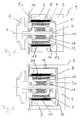
- Fig. 1 shows a canned pump 1 with an electronic commutated motor, the rotor 2 of which in a containment shell 5 rests, the one facing away from the can bottom
- An impeller 6 is attached to the end of the rotor 2.
- On the cylindrical outer surface of the can 5 is on the outside a film stand winding 4.
- the Foil stand winding 4 is radially outwards through a Stator core 3 held.
- the stator winding 4 has sensor windings, not shown, the Detect the positioning of the rotor in the containment can.
- the Stator windings 4 and the sensor windings are included the motor electronics 9 in electrical connection.
- the Motor electronics 9 takes over the electronic control of the windings in such a way that the magnetic Stator flow direction, caused by a Live winding with the magnetic Rotor flow direction, a certain angle in particular includes an average angle of 90 degrees. They don't sensor windings shown in the stator winding 4 integrated or placed on it serve as Position transmitter. The information from the rotor position sensor becomes the orderly advance of the Winding currents from one strand to the following from the motor electronics 9 used. In addition, the Information of the sensors 16, which on the Pump impeller 6 facing away from the can collar 5a are arranged to advance or control the Stator windings 4 are used.
- the engine electronics 9 is designed as a module, in particular as a cup-shaped one Module, the inner wall of the pot bottom on the The outer side of the containment shell is in contact, making a good one Heat transfer to the medium can be achieved. In addition, between the contact surfaces 13 Motor electronics 9 and the can bottom 5 a Thermal paste can be introduced.
- the engine electronics 9 also has a contact surface 14 with the stator core 3rd
- the rotor 2 is held by two bearings 10, wherein between the bearings 10 on the rotor 2 a sleeve-shaped Carrier element 11 is, which for reasons of weight is preferably made of plastic.
- the carrier element 11 holds a laminated core 12 which holds the permanent magnets 8 wearing.
- the permanent magnets 8 are either in axially extending grooves or are shape or non-positively attached to the laminated core 12.
- the electronically commutated shown in Fig. 2 Radial flux motor differs from that in FIG. 1 Motor shown in that the electronics 9 in the Motor housing is integrated, the motor housing 9 and the stator core 3 is cup-shaped.
- the Pot-shaped housing 9 includes with his cylindrical part of the stator core 3 and closes flush with the can collar 5a.
- the engine case with integrated electronics 9 lies with its Inside of the pot base and with its cylindrical Inside 14 on the outside of the pot Stand sheet metal package 3.
- the pot bottom 3a of the Stator laminated core 3 lies between the can bottom and the motor housing 9 and forms the Heat transfer resistance between engine electronics 9 and Containment shell 5.
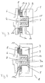
- Fig. 3 is an electronically commutated Axial flow motor shown for a canned pump 1, the stator winding on the pump impeller 6 facing side of the can collar 5a.
- the Stator winding 4 is facing away from the collar 5a Side held by the annular stator core 3.
- the module designed Motor electronics 9 with their contact surface 14.
- the rotor 2 is held by a bearing 10, the bearing 10 is in particular a plain bearing.
- the permanent magnets 8 are on the can collar 5a facing side of the pump impeller 6 arranged or poured.
- the permanent magnets 8 are approximately in radial region of the stator winding.
- the Motor electronics 9 is like the radial flux motor on the Outer wall of the containment can 5.
- the permanent magnets 8 are with their radially outward pointing end in the detection area of the sensor elements 16, the rotor position or the position of the Impeller arranged permanent magnets 8 or determine.
- the sensor elements 16 are coaxial around the Stator winding 4 are arranged and are electrically connected to the Motor electronics in connection.
- FIG. 4 Axial flux motor differs from that in FIG. 3 engine shown in that as in Fig. 2nd illustrated radial flux motor the stator core 3 as well as the motor housing with integrated motor electronics 9 is cup-shaped, again the stator winding 4 between the can collar 5a and the end face 15a of the stator core 3 lies.
- the inside of the pot Stator core 3 is completely on the Outer shell 5 on.
- the pot-shaped Stator core 3 is in turn in the pot-shaped Motor housing 9 a. Between the contact surfaces 14 of the Motor electronics 9 and the stator core 3 can be thermal paste, not shown.
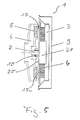
- Figure 5 describes a pump with an electronic commutated axial flux motor, in which the containment shell 5 is replaced by a flat separating body 20.
- the flat separator 20 is essentially a flat one Washer, on which the one pointing to the pump impeller 6 Side that encompasses the shaft 2 of the impeller 6 10 is attached centrally and on its other flat Side the stator winding 4 is applied, the annular stator winding 4 around a cylindrical part 21 can be arranged.
- Stator core 3 On the flat separator 20 facing end of the stator winding 4 is Stator core 3, which is for the magnetic Backflow of the stator winding 4 is used.
- the stator winding 4, the stator core 3 and additional Sensor elements 16 lie in the pot-shaped housing 9, which seals with the edge of the flat separating body 20 completes, so that the electrical or electronic Parts of the drive side protected against external influences are.
- the motor housing 9 also takes the required Motor electronics (control electronics and / or Control electronics).
Landscapes
- Engineering & Computer Science (AREA)
- Mechanical Engineering (AREA)
- General Engineering & Computer Science (AREA)
- Power Engineering (AREA)
- Microelectronics & Electronic Packaging (AREA)
- Structures Of Non-Positive Displacement Pumps (AREA)
- Windings For Motors And Generators (AREA)
- Insulation, Fastening Of Motor, Generator Windings (AREA)
- Reciprocating Pumps (AREA)
- Details And Applications Of Rotary Liquid Pumps (AREA)
Abstract
Description
Die Erfindung betrifft eine Spaltrohrpumpe mit einem die Pumpe antreibenden Motor, bei dem zwischen dem Rotor oder Laufrad und dem Ständer ein Spaltrohr insbesondere ein Spalttopf angeordnet ist.The invention relates to a canned pump with a Pump driving motor where between the rotor or Impeller and the stand in particular a can Can is arranged.
Spaltrohrpumpen werden fast ausschließlich mit Asynchronmaschinen in Drehstrom oder Wechselstrom betrieben, da Asynchronmaschinen eine hohe Fertigungsreife erreicht haben und sich durch ihre kompakte Bauweise und ihre Zuverlässigkeit ausweisen. Im kleinen und mittleren Leistungsbereich ist der Wirkungsgrad von Asynchronmaschinen jedoch ungenügend. Ebenso nachteilig ist der bei kleinen Asynchronmaschinen unverhältnismäßig große Aufwand an Elektronik für die stufenlose Regelung des Motors. Spaltrohrmotoren haben jedoch den Vorteil, daß die elektrische Antriebsseite hermetisch mittels des Spaltrohres bzw. Spalttopfes von den rotierenden Teilen sowie dem Fördermedium getrennt ist.Canned tube pumps are used almost exclusively with asynchronous machines operated in three-phase or alternating current, because Asynchronous machines have reached a high level of production readiness have and because of their compact design and their Show reliability. In small and medium Performance range is the efficiency of However, asynchronous machines are insufficient. Just as disadvantageous is disproportionate for small asynchronous machines great expenditure of electronics for the stepless regulation of the motor. However, canned motors have the advantage that the electric drive side hermetically by means of the Canned tube or can from the rotating parts and the medium is separated.
Aus der DE 16 38 272 ist eine Pumpe mit Spaltrohrmotor bekannt, dessen als Pumpenrotor ausgebildeter von der Förderflüssigkeit umspülter Rotor im Spaltrohr und dessen Motorwicklung auf der Außenseite des Spalt rohres angeordnet ist. Der Spaltrohrmotor ist ein kollektorloser Gleichstrommotor, dessen Permanentmagnete unmittelbar auf dem Pumpenrotor befestigt sind und dessen das Antriebsfeld steuernde Halbleiterelemente auf der Außenseite des Spaltrohres angeordnet sind. Die Ständerwicklung bei diesem Spaltrohrmotor besteht aus einzelnen Windungen, die bei der Montage nacheinander einzeln auf den Spalttopf aufgelegt werden oder einzeln in die Nuten des Ständerblechpakets eingelegt werden. Nachteilig ist hierbei, daß der Fertigungsaufwand zum Wickeln der Ständerwicklungen relativ hoch ist und beim Aufwickeln der Ständerwicklung vom Fertigungspersonal Fehler begangen werden können.From DE 16 38 272 is a pump with a canned motor known, the trained as a pump rotor by the Conveying liquid around the rotor in the can and whose motor winding on the outside of the can is arranged. The canned motor is a brushless DC motor, its permanent magnets are attached directly to the pump rotor and the semiconductor elements controlling the drive field the outside of the can are arranged. The Stator winding in this canned motor consists of individual turns, which are assembled one after the other placed individually on the can or individually be inserted into the grooves in the stator core. The disadvantage here is that the manufacturing costs for Winding the stator windings is relatively high and at Winding up the stator winding by the production personnel Mistakes can be made.
Aufgabe der Erfindung ist es daher, einen derartigen Spaltrohrmotor dahingehend weiter zu entwickeln, daß der Fertigungsaufwand verringert und die Funktionssicherheit erhöht wird.The object of the invention is therefore such Canned motor to further develop that the Manufacturing effort reduced and functional reliability is increased.
Erfindungsgemäß wird diese Aufgabe dadurch gelöst, daß die Ständerwicklung eine ein- oder mehrlagige Folie mit integrierten elektrisch leitenden Wicklungen ist oder eine Leiterplatine (Multilayer), die am Spaltrohr oder Spalttopf anliegt oder befestigt ist oder die Ständerwicklung eine Backlackwicklung ist, die insbesondere mit dem Spalttopf verbacken ist. Durch die vorteilsmäßige Verwendung einer ein- oder mehrlagigen Folie mit integrierten elektrischen leitenden Wicklungen verringert sich der Fertigungsaufwand erheblich, da lediglich die vorgefertigte Folie um den Spalttopf bzw. das Spaltrohr gelegt werden muß. Durch den Einsatz verschiedener vorgefertigter Folien oder Leiterplatinen kann der Spaltrohrmotor für unterschiedlichste Aufgaben in seiner Leistung dimensioniert werden. According to the invention this object is achieved in that the stator winding with a single or multi-layer film integrated electrically conductive windings is or a printed circuit board (multilayer) on the canned or Containment shell is attached or fastened or the Stator winding is a baked enamel that is baked in particular with the can. Through the advantageous use of a single or multi-layer Foil with integrated electrically conductive windings the manufacturing effort is significantly reduced because only the prefabricated film around the containment shell or the can must be placed. Because of the engagement various prefabricated foils or printed circuit boards the canned motor can be used for a wide variety of tasks be dimensioned in its performance.
Mittels einer Backlackwicklung läßt sich eine sehr enge Bewicklung des Spalttopfes erzielen, wobei insbesondere durch das Verbacken bzw. Einschmelzen der backlackwicklung mit dem Spalttopf eine besonders stabile Konstruktion erzielt wird. Die Wicklungen können hierdurch durch die auftretenden Feldkräfte nicht gegeneinander verschoben werden. Dadurch erniedrigen sich die bei herkömmlichen Wicklungen auftretenden Wicklungsgeräusche. Die oben aufgeführten Ausführungsformen zeichnen sich vorteilsmäßig dadurch aus, daß der Luftspalt zwischen Ständer und Rotor vorteilsmäßig nur von der Dicke des Spaltrohres bzw. Spalttopfes abhängt. Das Spaltrohr bzw. der Spalttopf hat somit vorteilsmäßig eine doppelte Funktion. Einerseits übernimmt es die Aufgabe als Wicklungsträger mit guter wärmeabfuhr und andererseits dient es zur Trennung der elektrischen Antriebsseite von dem Rotor.By means of a baked enamel coating a very tight Achieve winding of the containment shell, in particular by baking or melting the baking varnish with the can a particularly stable Construction is achieved. The windings can this does not result from the occurring field forces be moved against each other. This will lower you those that occur with conventional windings Winding noise. The ones listed above Embodiments are advantageously characterized by this from that the air gap between the stator and rotor advantageously only from the thickness of the can or Can depends on. The can or the can has thus advantageously a double function. On the one hand it takes on the task of winding carriers with good heat dissipation and on the other hand it serves to separate the electric drive side of the rotor.
Die für die Ständerwicklung eingesetzte ein- oder mehrlagige Folie kann vorteilsmäßig mittels eines Ätzverfahrens hergestellt werden. Hierbei werden die Windungen in einem Arbeitsschritt hergestellt, wodurch sich Fehler bei der Herstellung der Wicklungen auf ein Minimum reduzieren. Auch sind derartige Folien relativ kostengünstig herzustellen. Sie zeichnen sich besonders durch ihre flachen Abmessungen und ihre hohe Lebensdauer aus.The one used for the stator winding or multilayer film can advantageously by means of a Etching process are produced. Here, the Turns made in one step, whereby errors in the manufacture of the windings Reduce minimum. Such films are also relative inexpensive to manufacture. You stand out due to their flat dimensions and their long service life out.
Die Ständerwicklung liegt dabei vorteilsmäßig an der zylindrischen Außenseite des Spaltrohres bzw. Spalttopfes an. Ein derartiger Motor wird üblicherweise als Radialflußmotor bezeichnet. Ebenfalls vorteilsmäßig ist es, wenn das Spaltrohr oder der Spalttopf einen an seiner dem Pumpenlaufrad zugewandten offenen Seite angeformten, radial nach außen gerichteten Kragen (Lagerschild) hat, wobei die Ständerwicklung an der dem Pumpenlaufrad abgewandten Seite des Kragens des Spalttopfes oder Spaltrohres anliegt. Ein derartiger Motor wird auch Axialflußmotor genannt.The stator winding is advantageously due to the cylindrical outside of the can or can on. Such an engine is usually called Radial flux motor called. It is also advantageous it when the can or the can one against his molded open side facing the pump impeller, has a radially outwardly directed collar (end shield), the stator winding on the pump impeller opposite side of the collar of the containment shell or Canned is present. Such an engine will also Axial flow motor called.
Zudem ist es vorteilsmäßig, wenn beim Radialflußmotor an der dem Spaltrohr zugewandten Seite des Rotors oder des Förderrades gleichmäßig um die Rotorachse angeordnet Permanentmagnete befestigt sind. Die Permenantmagnete dienen dabei gleichzeitig zur Erzeugung des Antriebsdrehmomentes sowie zur Übertragung von Sendesignalen. Auch ist es vorteilsmäßig, wenn die Permanentmagnete segmentförmig sind, wobei die Permanentmagnete an einem Trägerelement befestigt oder eingeformt sind, wobei das Trägerelement form- oder kraftschlüssig vom Rotor gehalten ist. Das Trägerelement ist dabei vorzugsmäßig ein auf den Rotor aufgeschobenes hülsenförmiges Kunststoffteil, welches mit seiner äußeren Mantelfläche form- oder kraftschlüssig ein Blechpaket hält, wobei die Permanentmagnete in oder an der dem Kunststoffteil abgewandten Seite des Blechpaketes einliegen bzw. befestigt sind. Beim Radialflußmotor sind die Permanentmagnete am Rotor befestigt, so daß sich sich ihre Längsausdehnung vorzugsmäßig parallel zur Rotorachse erstreckt. Sind die Permanentmagnete am Laufrad angeordnet, so übernimmt das Laufrad die Rotorfunktion. Die Permanentmagnete liegen dann koaxial zur Laufradachse und haben die Form von flachen Ringausschnitten bzw. Ringsektoren.It is also advantageous if the radial flux motor is on the side of the rotor facing the can or Conveyor wheel arranged evenly around the rotor axis Permanent magnets are attached. The Permenant magnets serve at the same time to generate the Drive torque and for the transmission of Broadcast signals. It is also advantageous if the Permanent magnets are segment-shaped, the Permanent magnets attached to a support element or are molded, the carrier element being shaped or is held non-positively by the rotor. The support element is preferably a slid onto the rotor sleeve-shaped plastic part, which with its outer A sheet metal package with a positive or non-positive surface holds, the permanent magnets in or on the Plastic part facing away from the laminated core inlaid or fastened. When radial flow motor are the permanent magnets attached to the rotor so that themselves their longitudinal extent preferably parallel to the rotor axis extends. Are the permanent magnets on the impeller arranged, the impeller takes over the rotor function. The permanent magnets are then coaxial with the impeller axis and have the shape of flat ring cutouts or Ring sectors.
Der Radialflußmotor ist vorzugsweise ein Asynchronmotor oder ein elektronisch kommutierter Motor, der Axialflußmotor ein elektrisch kommutierter Motor. Vorteilsmäßig sind die Permanentmagnete flach ausgebildet, damit ein geringeres Gewicht, niedrigere Fertigungskosten sowie eine kompaktere bzw. kleinere Bauweise der Pumpe erzielt wird.The radial flux motor is preferably an asynchronous motor or an electronically commutated motor that Axial flow motor is an electrically commutated motor. The permanent magnets are advantageously flat trained to be lighter, lower Manufacturing costs as well as a more compact or smaller one Construction of the pump is achieved.
Es ist von Vorteil, wenn eine Elektronik die Kommutierung der Ständerwicklung zur Erzeugung des sich drehenden Ständermagnetfeldes vornimmt, wobei die einzelnen Wicklungen der Ständerwicklung mit der Elektronik in elektrischer Verbindung sind. Der Wirkungsgrad eines derartigen elektronisch kommutierten bürstenlosen Motors ohne Ansteuerelektronik ist vorteilsmäßig deutlich höher als bei vergleichbaren Asynchronmaschinen. Sind die Permanentmagnete am Rotor angeordnet, so ist es vorteilsmäßig, daß die Ständerwicklung an der zylindrischen Außenseite des Spaltrohres oder Spalttopfes anliegt. Ein derartiger elektronisch kommutierter Motor wird auch als Radialflußmotor bezeichnet.It is beneficial if an electronics commutation the stator winding to generate the rotating Stator magnetic field, the individual Stator winding with electronics in electrical connection. The efficiency of a such electronically commutated brushless motor without control electronics is advantageously significantly higher than comparable asynchronous machines. If the permanent magnets are arranged on the rotor, it is advantageous that the stator winding on the cylindrical outside of the can or can is present. Such an electronically commutated motor is also known as a radial flux motor.
Sind dagegen die Permanentmagnete am Laufrad angeordnet, so ist es vorteilsmäßig, daß das Spaltrohr oder der Spalttopf einen an seiner dem Pumpenlaufrad zugewandten offenen Seite angeformten radialen nach außen gerichteten Kragen (Lagerschild) hat, wobei die Ständerwicklung an der dem Pumpenlaufrad abgewandten Seite des Kragens des Spalttopfes oder des Spaltrohres anliegt. Ein derartiger auch als elektronisch kommutierter Axialflußmotor bezeichneter Motor weist sich durch eine gegenüber dem Radialflußmotor noch kompaktere Bauweise aus. Ein weiterer Vorteil des Axialflußmotors gegenüber dem Radialflußmotor besteht darin, daß durch die höheren Strömungsgeschwindigkeiten am Laufrad, verglichen mit den Strömungsgeschwindigkeiten im Spalttopf, die magnetischen Ablagerungen an den Permanentmagneten kleiner sind, wodurch die Drehmomentübertragung zwischen Stator und Rotor weniger stark beeinflußt sind. If, on the other hand, the permanent magnets are arranged on the impeller, so it is advantageous that the can or Canister one on its side facing the pump impeller open side molded radial outward Has collar (end shield), with the stator winding on the side of the collar of the Can or the can. Such one also as an electronically commutated axial flux motor designated engine has one opposite Radial flow motor even more compact design. A Another advantage of the axial flow motor over that Radial flow motor is that by the higher Flow velocities at the impeller compared to the Flow velocities in the containment shell, the magnetic ones Deposits on the permanent magnets are smaller, whereby the torque transmission between stator and Rotor are less affected.
Auch ist es vorteilsmäßig, wenn die Folie mindestens eine zusätzliche Sensorwicklung hat oder daß die Ständerwicklung eine zusätzliche Folie mit mindestens einer Sensorwicklung hat oder daß in der Ständerfolienwicklung Sensoren einliegen oder daß mindestens eine Folie mindestens einen induktiven kapazitiven oder ohmischen Sensor hat. Durch die platzsparende Integration derartiger Sensoren, die bei der Rotorpositionserfassung derartiger bürstenloser elektronisch kommutierter Motoren notwendig sind, wird eine Kosten- und Gewichtsersparnis erzielt.It is also advantageous if the film has at least one has additional sensor winding or that the Stator winding with an additional film at least has a sensor winding or that in the Stator film winding sensors or that at least one film at least one inductive capacitive or ohmic sensor. Through the space-saving integration of such sensors, which at the rotor position detection of such brushless electronically commutated motors are necessary achieved a cost and weight saving.
Auch ist es vorteilsmäßig, wenn das Spaltrohr oder der Spalttopf aus einem weichmagnetischen Werkstoff oder Kunststoff ist. Hierdurch wird eine effektive Luftspaltverringerung erzielt, wodurch der Wirkungsgrad des Motors ebenfalls verbessert wird.It is also advantageous if the can or Can from a soft magnetic material or Is plastic. This will be an effective one Air gap reduction is achieved, which increases efficiency the engine is also improved.
Wird die Spaltrohrpumpe zum Fördern eines Fördermediums eingesetzt, bei dem die Druck- bzw. Temperaturbeanspruchung eine Verringerung der Spaltrohr- bzw. Spalttopfdicke zuläßt, ist es vorteilsmäßig die Ständerwicklung und/oder Sensorwicklung in die vom Rotor oder vom Laufrad abgewandte Seite des Spaltrohres oder Spalttopfes einzulegen, einzugießen oder einzuschließen. Hierdurch lassen sich zusätzliche Fertigungskosteneinsparungen erzielen. Auch trägt das Eingießen der Ständerfolienwicklungen in die Außenwand des vorteilsmäßig aus Kunststoff gefertigten Spaltrohres oder Spalttopfes zur Gesamtstabilität des Spaltrohres bzw. Spaltttopfes bei.The canned pump is used to pump a medium used in which the pressure or Temperature stress a reduction in the can or the containment shell thickness, it is advantageously the Stator winding and / or sensor winding in the rotor or side of the cannula facing away from the impeller or Insert, pour or enclose containment can. This allows additional Achieve manufacturing cost savings. That also carries Pour the stator foil windings into the outer wall of the advantageously made of plastic can or containment shell for overall stability of the can or can with.
An der dem Spaltrohr oder dem Spalttopf abgewandten Seite der Ständerwicklung ist vorteilsmäßig ein Ständerblechpaket, wobei das Ständerblechpaket insbesondere zylinder- oder topfförmig ist. Das Ständerblechpaket ist dabei mit seiner Innenfläche und/oder Bodeninnenseite mit dem Spaltrohr in Kontakt, wodurch ein guter Wärmeübergang zwischen Ständerblechpaket und Spaltrohr bzw. Spalttopf gegeben ist. Das Ständerblechpaket trägt ebenfalls vorteilsmäßig zur Stabilität der Statorkonstruktion bei.On the side facing away from the can or the can the stator winding is advantageously a Stator core package, the stator core package is in particular cylindrical or pot-shaped. The Stand sheet metal package is with its inner surface and / or bottom inside in contact with the can, which ensures good heat transfer between Stand sheet metal package and can or can is. The stator core package also bears advantageously to the stability of the stator construction.
Das Ständerblechpaket liegt mit seiner zylindrischen Innenseite beim Radialflußmotor oder mit seiner Stirnseite beim Axialmotor an den Ständerwicklungen an. Das Ständerblechpaket ist vorzugsmäßig aus einem beschichteten weichmagnetischen oder Sinter-Material. Auch kann das Ständerblechpaket ein Ringbandkern sein, wobei eine metallische Ronde als magnetischer Rückschluß dient.The stator core is located with its cylindrical Inside the radial flux motor or with it Front side of the axial motor on the stator windings. The stator core is preferably made of one coated soft magnetic or sintered material. The stator core can also be a toroidal core, with a metallic disc as a magnetic yoke serves.
Auch ist es von Vorteil, wenn die Motorelektronik neben dem Stator angeordnet ist bzw. an diesen anschließt, insbesondere an der dem Pumpenlaufrad abgewandten Seite des Stators, wobei das Statorblechpaket als Kühlkörper und gleichzeitig zur elektrischen Abschirmung für die Elektronik dient. Durch das direkte Anliegen der Elektronik am Statorblechpaket bzw. am Spaltrohr bzw. Spalttopf insbesondere an dessen Boden wird die von der Elektronik erzeugte Wärme direkt an das Fördermedium übertragen. Zusätzliche Kühlkörper für die Elektronik sind nicht mehr notwendig, wodurch sich die Abmessungen des Motors sowie dessen Fertigungskosten reduzieren lassen. Die Motorelektronik ist dabei vorzugsweise als aufsteckbares Modul ausgebildet, so daß je nach späterem Einsatzgebiet und Leistungsauslegung des Motors ein entsprechendes Elektronikmodul gewählt werden kann. An dem Motorgehäuse und/oder der Motorelektronik sind Steckkontakte (Stecker oder Buchse), die vorzugsweise in axialer Richtung angeordnet sind. Am Spalttopf und/oder dem Statorblechpaket und/oder der Ständerwicklung sind gleichfalls Kontakte (Stecker oder Buchse) angeordnet. Beim axialen Zusammenfügen der Teile werden gleichzeitig die Steckverbindungen geschlossen. Die Motorelektronik bzw. das Elektronikmodul kann zudem einen Teil des Motorgehäuses bilden. Durch diese Integration läßt sich der Montageaufwand weiter reduzieren. Der Spalttopf läßt sich vorteilsmäßig durch einen flachen, insbesondere scheibenförmigen Trennkörper ersetzen, wobei an seiner dem Pumpenlaufrad abgewandten Seite die Ständerwicklung anliegt. Durch das Ersetzen des Spalttopfes durch den flachen Trennkörper wird die Pumpe in ihren Abmessungen kleiner und kompakter, und es entfällt der aufwendig zu fertigende Spalttopf.It is also an advantage if the engine electronics in addition is arranged or connects to the stator, especially on the side facing away from the pump impeller of the stator, the stator laminated core as a heat sink and at the same time as electrical shielding for the Electronics. Through the direct concern of the Electronics on the stator laminated core or on the can or Containment shell in particular at the bottom of which is from the Electronics generate heat directly to the fluid transfer. Additional heat sinks for the electronics are no longer necessary, which increases the dimensions of the engine and its manufacturing costs to let. The engine electronics is preferably as attachable module designed so that depending on the later Field of application and power rating of the engine appropriate electronics module can be selected. On the motor housing and / or the motor electronics Plug contacts (plug or socket), preferably in are arranged in the axial direction. At the containment shell and / or the stator core and / or the stator winding likewise contacts (plug or socket) arranged. When the parts are joined axially, they are simultaneously the plug connections closed. The engine electronics or the electronics module can also be part of the Form the motor housing. This integration allows further reduce the assembly effort. The containment can leaves itself advantageously by a flat, in particular replace disk-shaped separating body, being at his the stator winding facing away from the pump impeller is present. By replacing the can with the the pump is flat in its dimensions smaller and more compact, and there is no need for complicated manufacturing containment can.
Es ist ebenfalls von Vorteil, wenn an der dem Pumpenlaufrad abgewandten Seite des Kragens des Spaltrohrs oder Spalttopfes mindestens ein Sensorelement, insbesondere Temperatursensor, angeordnet ist. Ebenfalls vorteilsmäßig ist es, wenn mittels des bzw. der Temperatursensoren die Temperatur des Lagerschildes bzw. Kragens des Spalttopfes erfaßbar bzw. meßbar ist und durch die mittels der Permanentmagnete in den nicht stromführenden Strangwicklungen der Ständerwicklung induzierten Spannung die Rotorlage, Rotordrehzahl, sowie Rotordrehrichtung erfaßbar bzw. meßbar ist, wobei die Meßsignale einer Auswertelektronik zugeführt werden, die den Volumenstrom des Fördermediums bestimmt. Auch kann vorteilsmäßig die gemessene Stromstärke in den einzelnen Ständerwicklungen zur Bestimmung des Volumenstroms mittels der Auswertelektronik herangezogen werden. Durch die Auswertelektronik läßt sich zudem vorteilsmäßig und kostengünstig eine Wärmemengenregelung der Pumpe vornehmen. Zur Verbesserung der angestrebten (kalorimetrischen) Volumenstrommessung wird die Lagerschildfläche des Spalttopfes speziell ausgeformt, um die Sensoren in einen guten Wärmekontakt mit dem Fördermedium bzw. der Lagerschildfläche des Spalttopfes zu bringen.It is also an advantage if on the Pump impeller facing away from the collar of the Can or at least one sensor element, in particular temperature sensor. Likewise It is advantageous if by means of the Temperature sensors the temperature of the end shield or Collar of the containment shell is detectable or measurable and by means of the permanent magnets in the not current-carrying phase windings of the stator winding induced voltage the rotor position, rotor speed, as well Direction of rotor rotation is detectable or measurable, the Measurement signals are supplied to an electronic evaluation system determines the volume flow of the medium. Can too advantageously the measured current in each Stator windings for determining the volume flow can be used by means of the evaluation electronics. By the evaluation electronics can also be advantageous and cost-effective heat quantity control of the pump make. To improve the target (calorimetric) volume flow measurement is the End shield surface of the containment shell specially shaped to the sensors in good thermal contact with the Pumped medium or the end shield surface of the containment shell bring to.
Durch den besonderen Aufbau der vorbeschriebenen Spaltrohrpumpe läßt sich eine derartige Spaltrohrpumpe kostengünstiger, schneller und leichter montieren. Vorteilsmäßig ist es dabei, wenn die Teile der Spaltrohrpumpe in axialer, insbesondere aus einer axialen Richtung aneinandergefügt werden. Dazu wird in einem ersten Prozeßschritt das Laufrad in eine Haltevorrichtung eingespannt und in einem zweiten Prozeßschritt die Welle mit dem beim Radialflußmotor zugehörigen Rotor in das Laufrad eingeschoben und in einem dritten Prozeßschritt der Spalt topf mit vormontierter Wicklung aufgeschoben und in einem vierten Prozeßschritt der Statorrückschluß bzw. das Statorblechpaket auf den Spalttopf aufgeschoben und in einem fünften Prozeßschritt das Elektronikmodul und das Gehäuse über den Spalttopf mit Ständerwicklung geschoben, wodurch die Antriebsseite der Spaltrohrpumpe verschlossen ist. Bei einem derartigen Montageverfahren entfallen die bei bisher bekannten Montageverfahren notwendigen radialen Fügeprozesse, wodurch die Bestückungsmaschinen in ihrer Konstruktion wesentlich vereinfacht und dadurch billiger herstellbar sind.Due to the special structure of the above A canned pump of this type can be used Assemble cheaper, faster and easier. It is advantageous if the parts of the Canned tube pump in the axial, especially from an axial Direction to be joined together. This is done in one first process step the impeller in a holding device clamped and in a second process step the shaft with the rotor associated with the radial flux motor in the Impeller inserted and in a third process step the gap pot with the pre-assembled winding is pushed on and in a fourth process step the stator inference or the stator laminated core is pushed onto the containment shell and in a fifth process step the electronics module and the housing over the containment shell with stator winding pushed, creating the drive side of the canned pump is closed. With such an assembly method the assembly methods known to date are eliminated necessary radial joining processes, whereby the Placement machines essential in their construction simplified and therefore cheaper to manufacture.
Ein weiteres vorteilsmäßiges Verfahren zur Montage der Ständerwicklung sieht vor, daß die Folienwicklung um die zylindrische Außenmantelfläche oder an den Kragen des Spalttopfes bzw. Spaltrohres gelegt oder auf diesen aufgeschoben wird und mittels einer Schraub-, Kleb-, Schweiß-, Klemm- oder Nietverbindung an diesem befestigt wird. Auch können die Ständerwicklungen einzeln auf die zylindrische Außenmantelfläche oder an den Kragen des Spalttopfes bzw. Spaltrohres aufgewickelt bzw. aufgelegt und mittels einer Klemm- oder Klebvorrichtung in Position gehalten werden. Es ist ebenfalls vorteilsmäßig, wenn die Ständerwicklungen einzeln oder im Verbund auf die zylindrische Außenmantelfläche oder den Kragen des Spalttopfes aufgewickelt, aufgelegt oder in diese eingeätzt werden und anschließend mit einer Substanz umgossen werden, die nach dem Gießprozeß hart wird und die Wicklungen auf dem Spalttopf in Position hält. Mittels dieser Verfahren läßt sich die Ständerwicklung schnell, einfach und kostengünstig am Spalttopf bzw. an dessen zylindrischer Außenmantelfläche oder scheibenförmigen Kragen montieren.Another advantageous method for assembling the Stator winding provides that the film winding around the cylindrical outer surface or on the collar of the Can or can placed or on this is pushed on and by means of a screw, adhesive, Welded, clamped or riveted connection attached to this becomes. The stator windings can be individually on the cylindrical outer surface or on the collar of the Can or can is wound or placed on and in position by means of a clamping or gluing device being held. It is also advantageous if the Stator windings individually or in combination on the cylindrical outer surface or the collar of the The can is wound up, placed on or in it be etched and then with a substance are cast, which becomes hard after the casting process and holds the windings in position on the containment can. Using these methods, the stator winding can be fast, easy and inexpensive at the containment can or on whose cylindrical outer surface or Assemble the disc-shaped collar.
Nachfolgend wird der erfindungsgemäße Gegenstand anhand der Zeichnungen näher erläutert.The subject matter of the invention is described below the drawings explained in more detail.
Es zeigen:
- Fig. 1:
- Eine Spaltrohrpumpe mit einem elektronisch kommutierten Radialflußmotor mit integrierter Elektronik;
- Fig. 2:
- Eine Spaltrohrpumpe mit einem elektronisch kommutierten Radialflußmotor mit im Gehäuse integrierter Elektronik.
- Fig. 3:
- Eine Spaltrohrpumpe mit einem elektronisch kommutierten Axialflußmotor mit integrierter Elektronik.
- Fig. 4:
- Eine Spaltrohrpumpe mit einem elektronisch kommutierten Axialflußmotor mit im Gehäuse integriertem Elektronikmodul.
- Fig. 5:
- Eine Pumpe mit einem elektrischen kommutierten Axialflußmotor, bei der das Spaltrohr durch einen flachen Trennkörper ersetzt ist.
- Fig. 1:
- A canned pump with an electronically commutated radial flow motor with integrated electronics;
- Fig. 2:
- A canned pump with an electronically commutated radial flow motor with electronics integrated in the housing.
- Fig. 3:
- A canned pump with an electronically commutated axial flow motor with integrated electronics.
- Fig. 4:
- A canned pump with an electronically commutated axial flow motor with an electronics module integrated in the housing.
- Fig. 5:
- A pump with an electrical commutated axial flow motor, in which the can is replaced by a flat separator.
Fig. 1 zeigt eine Spaltrohrpumpe 1 mit einem elektronisch
kommutierten Motor, dessen Rotor 2 in einem Spalttopf 5
einliegt, wobei an dem dem Spalttopfboden abgewandten
Ende des Rotors 2 ein Laufrad 6 befestigt ist. Auf der
zylindrischen Mantelfläche des Spalttopfes 5 liegt außen
eine Folienständerwicklung 4 auf. Die
Folienständerwicklung 4 ist radial nach außen durch ein
Ständerblechpaket 3 gehalten. Die Ständerwicklung 4 hat
nicht dargestellte Sensorwicklungen, die die
Positionierung des Rotors im Spalttopf erfassen. Die
Ständerwicklungen 4 sowie die Sensorwicklungen sind mit
der Motorelektronik 9 in elektrischer Verbindung. Die
Motorelektronik 9 übernimmt die elektronische Ansteuerung
der Wicklungen in der Weise, daß die magnetische
Ständerflußrichtung, hervorgerufen durch eine
stromführende Wicklung mit der magnetischen
Läuferflußrichtung, einen bestimmten Winkel insbesondere
einen mittleren Winkel von 90 Grad einschließt. Die nicht
dargestelltenSensorwicklungen, die in der Ständerwicklung
4 integriert oder auf diese aufgelegt sind, dienen als
Stellungsgeber. Die Information des Rotorstellungsgebers
wird dabei zum geordneten Weiterschalten der
Wicklungsströme von einem Strang auf den folgenden von
der Motorelektronik 9 verwendet. Zusätzlich können die
Informationen der Sensoren 16, die an der dem
Pumpenlaufrad 6 abgewandten Seite des Spaltrohrkragens 5a
angeordnet sind zur Weiterschaltung bzw. Ansteuerung der
Ständerwicklungen 4 verwendet werden. Die Motorelektronik
9 ist als Modul ausgebildet insbesondere als topfförmiges
Modul, wobei die Topfbodeninnenwand an der
Spalttopfbodenaußenseite anliegt, wodurch sich ein guter
Wärmeübergang auf das Fördermedium erreichen läßt.
Zusätzlich kann zwischen die Anlageflächen 13 der
Motorelektronik 9 und des Spalttopfbodens 5 eine
Wärmeleitpaste eingebracht werden. Die Motorelektronik 9
hat zudem eine Anlagefläche 14 mit dem Ständerblechpaket
3.Fig. 1 shows a
Der Rotor 2 ist von zwei Lagern 10 gehalten, wobei
zwischen den Lagern 10 auf dem Rotor 2 ein hülsenförmiges
Trägerelement 11 ist, welches aus Gewichtsgründen
vorzugsmäßig aus Kunststoff ist. Das Trägerelement 11
hält ein Blechpaket 12, welches die Permanentmagnete 8
trägt. Die Permanentmagnete 8 liegen dabei entweder in
sich axial erstreckenden Nuten ein oder sind form- oder
kraftschlüssig am Blechpaket 12 befestigt.The
Der in Fig. 2 dargestellte elektronisch kommutierte
Radialflußmotor unterscheidet sich von dem in Fig. 1
dargestellten Motor dadurch, daß die Elektronik 9 in das
Motorgehäuse integriert ist, wobei das Motorgehäuse 9
sowie das Ständerblechpaket 3 topfförmig ist. Das
topfförmige Gehäuse 9 umfaßt dabei mit seinem
zylindrischen Teil das Ständerblechpaket 3 und schließt
mit dem Spaltrohrkragen 5a bündig ab. Das Motorgehäusee
mit integrierter Elektronik 9 liegt mit seiner
Topfbodeninnenseite sowie mit seiner zylindrischen
Innenseite 14 an der Topfaußenseite des
Ständerblechpaketes 3 an. Der Topfboden 3a des
Ständerblechpaketes 3 liegt zwischen dem Spalttopfboden
und dem Motorgehäuse 9 ein und bildet den
Wärmeübergangswiderstand zwischen Motorelektronik 9 und
Spalttopf 5.The electronically commutated shown in Fig. 2
Radial flux motor differs from that in FIG. 1
Motor shown in that the
In Fig. 3 ist ein elektronisch kommutierter
Axialflußmotor für eine Spaltrohrpumpe 1 dargestellt,
wobei die Ständerwicklung an der dem Pumpenlaufrad 6
abgewandten Seite des Spalttopfkragens 5a anliegt. Die
Ständerwicklung 4 wird auf ihre dem Kragen 5a abgewandten
Seite von dem ringförmigen Ständerblechpaket 3 gehalten.
An der der Ständerwicklung abgewandten Sirnseite des
Ständerblechpakets 3 liegt die als Modul ausgebildete
Motorelektronik 9 mit ihrer Anlagefläche 14 an. Der Rotor
2 ist von einem Lager 10 gehalten, wobei das Lager 10
insbesondere ein Gleitlager ist.In Fig. 3 is an electronically commutated
Axial flow motor shown for a
Die Permanentmagnete 8 sind an der dem Spalttopfkragen 5a
zugewandten Seite des Pumpenlaufrades 6 angeordnet bzw.
eingossen. Die Permanentmagnete 8 sind dabei ungefähr im
radialen Bereich der Ständerwicklung angeordnet. Die
Motorelektronik 9 liegt wie beim Radialflußmotor an der
Spalttopfbodenaußenwand 5 an.The
Die Permanentmagnete 8 sind mit ihrem radial nach außen
zeigenden Ende im Erfassungsbereich der Sensorelemente
16, die die Rotorposition bzw. die Position der am
Laufrad angeordneten Permanentmagnete 8 erfassen bzw.
bestimmen. Die Sensorelemente 16 sind koaxial um die
Ständerwicklung 4 angeordnet und sind elektrisch mit der
Motorelektronik in Verbindung.The
Der in Fig. 4 dargestellte elektronisch kommutierte
Axialflußmotor unterscheidet sich von dem in Fig. 3
dargestellten Motor dadurch, daß wie beim in Fig. 2
dargestellten Radialflußmotor das Ständerblechpaket 3
sowie das Motorgehäuse mit integrierter Motorelektronik 9
topfförmig ist, wobei wiederum die Ständerwicklung 4
zwischen dem Spalttopfkragen 5a und der Stirnseite 15a
des Ständerblechpakets 3 einliegt. Die Topfinnenseite des
Ständerblechpakets 3 liegt vollständig an der
Spalttopfaußenseite 5 an. Das topfförmige
Ständerblechpaket 3 liegt seinerseits im topfförmigen
Motorgehäuse 9 ein. Zwischen den Anlageflächen 14 der
Motorelektronik 9 und des Ständerblechpakets 3 kann eine
nicht dargestellte Wärmeleitpaste sein.The electronically commutated shown in Fig. 4
Axial flux motor differs from that in FIG. 3
engine shown in that as in Fig. 2nd
illustrated radial flux motor the
Figur 5 beschreibt eine Pumpe mit einem elektronisch
kommutierten Axialflußmotor, bei der der Spalttopf 5
durch einen flachen Trennkörper 20 ersetzt ist. Der
flache Trennkörper 20 ist im wesentlichen eine flache
Scheibe, an dessen der zum Pumpenlaufrad 6 zeigenden
Seite das die Welle 2 des Laufrades 6 umgreifende Lager
10 zentrisch befestigt ist und an dessen anderer flachen
Seite die Ständerwicklung 4 anliegt, wobei die
ringförmige Ständerwicklung 4 um ein zylindrisches Teil
21 angeordnet sein kann. An der dem flachen Trennkörper
20 abgewandten Stirnseite der Ständerwicklung 4 liegt das
Ständerblechpaket 3 an, welches für den magnetischen
Rückfluß der Ständerwicklung 4 dient. Die Ständerwicklung
4, das Ständerblechpaket 3 sowie zusätzliche
Sensorelemente 16 liegen im topfförmigen Gehäuse 9 ein,
welches mit dem Rand des flachen Trennkörpers 20 dichtend
abschließt, so daß die elektrischen bzw. elektronischen
Teile der Antriebsseite gegen äußere Einflüsse geschützt
sind. Das Motorgehäuse 9 nimmt ebenfalls die benötigte
Motorelektronik (Regelungselektronik und/oder
Steuerelektronik) auf.Figure 5 describes a pump with an electronic
commutated axial flux motor, in which the
Claims (17)
Applications Claiming Priority (3)
| Application Number | Priority Date | Filing Date | Title |
|---|---|---|---|
| DE4438132 | 1994-10-27 | ||
| DE4438132A DE4438132A1 (en) | 1994-10-27 | 1994-10-27 | Canned pump |
| EP95114761A EP0711019B2 (en) | 1994-10-27 | 1995-09-19 | Canned pump |
Related Parent Applications (1)
| Application Number | Title | Priority Date | Filing Date |
|---|---|---|---|
| EP95114761.0 Division | 1995-09-19 |
Publications (3)
| Publication Number | Publication Date |
|---|---|
| EP0877463A2 true EP0877463A2 (en) | 1998-11-11 |
| EP0877463A3 EP0877463A3 (en) | 1999-12-29 |
| EP0877463B1 EP0877463B1 (en) | 2005-04-13 |
Family
ID=6531669
Family Applications (2)
| Application Number | Title | Priority Date | Filing Date |
|---|---|---|---|
| EP98111587A Expired - Lifetime EP0877463B1 (en) | 1994-10-27 | 1995-09-19 | Canned pump |
| EP95114761A Expired - Lifetime EP0711019B2 (en) | 1994-10-27 | 1995-09-19 | Canned pump |
Family Applications After (1)
| Application Number | Title | Priority Date | Filing Date |
|---|---|---|---|
| EP95114761A Expired - Lifetime EP0711019B2 (en) | 1994-10-27 | 1995-09-19 | Canned pump |
Country Status (5)
| Country | Link |
|---|---|
| EP (2) | EP0877463B1 (en) |
| JP (1) | JP3739838B2 (en) |
| KR (1) | KR100332965B1 (en) |
| DE (3) | DE4438132A1 (en) |
| ES (1) | ES2129719T3 (en) |
Cited By (6)
| Publication number | Priority date | Publication date | Assignee | Title |
|---|---|---|---|---|
| EP1126177A2 (en) * | 2000-02-16 | 2001-08-22 | WILO GmbH | Electric hydraulic interface |
| EP1178212A2 (en) * | 2000-08-03 | 2002-02-06 | Claber S.P.A. | Water cooled centrifugal pump |
| EP1204194A1 (en) * | 2000-11-03 | 2002-05-08 | WILO GmbH | Axially plugable electronic housing |
| EP1387087A2 (en) * | 2002-07-29 | 2004-02-04 | Wilo Ag | Method for determining the flow rate in a pump |
| US8360755B2 (en) | 2005-04-02 | 2013-01-29 | Pierburg Gmbh | Wet-running pump |
| DE10065796B4 (en) * | 2000-11-03 | 2020-12-24 | Wilo Se | Axially plug-in electronics |
Families Citing this family (38)
| Publication number | Priority date | Publication date | Assignee | Title |
|---|---|---|---|---|
| DE19824345A1 (en) | 1998-06-02 | 1999-12-09 | Wilo Gmbh | Canned tube pump with winding carrier |
| DE19934382A1 (en) * | 1999-07-22 | 2001-02-01 | Bosch Gmbh Robert | Liquid pump |
| DE19939522A1 (en) | 1999-08-20 | 2001-02-22 | Wilo Gmbh | Centrifugal pump driven by an electric motor with external rotor |
| DE19940457A1 (en) * | 1999-08-25 | 2001-03-01 | Wilo Gmbh | Axial flow motor |
| DE19956380C1 (en) * | 1999-11-24 | 2001-01-04 | Bosch Gmbh Robert | Fluid pump for vehicle cooling and heating systems has plastics motor housing with claw plates of claw pole stator formed as integral components thereof |
| DE10025190A1 (en) | 2000-05-20 | 2001-12-06 | Wilo Gmbh | Canned motor with foil canned |
| DE10051403A1 (en) | 2000-10-17 | 2002-06-13 | Minebea Co Ltd | Rotor assembly for an electric motor and internal rotor electric motor |
| JP2002205010A (en) * | 2001-01-09 | 2002-07-23 | Citizen Watch Co Ltd | Brushless vibration motor unit |
| GB0105722D0 (en) * | 2001-03-08 | 2001-04-25 | Lucas Industries Ltd | Improvements in electric motor driven hydraulic pumps |
| DE10144653B4 (en) * | 2001-09-11 | 2006-05-11 | Ate Antriebstechnik Und Entwicklungs Gmbh | Permanently energized electromechanical machine for operation in liquids and gases |
| DE10157194A1 (en) | 2001-11-23 | 2003-06-05 | Wilo Gmbh | Canned tube pump with sensor |
| US6814549B2 (en) | 2002-02-28 | 2004-11-09 | Standex International Corp. | Liner for fluid pump motor |
| US6884043B2 (en) | 2002-02-28 | 2005-04-26 | Standex International Corp. | Fluid circulation path for motor pump |
| EP1478854B1 (en) * | 2002-02-28 | 2005-12-14 | Standex International Corporation | Motor pump |
| US6863504B2 (en) | 2002-02-28 | 2005-03-08 | Standex International Corp. | Fluid pump relief valve |
| US6847140B2 (en) | 2002-02-28 | 2005-01-25 | Standex International Corp. | Fluid barrier for motor rotor |
| US6837688B2 (en) | 2002-02-28 | 2005-01-04 | Standex International Corp. | Overheat protection for fluid pump |
| DE10307708A1 (en) † | 2003-02-24 | 2004-09-09 | Lenze Drive Systems Gmbh | Method for monitoring the temperature of an electric motor |
| DE10318702A1 (en) * | 2003-04-24 | 2005-03-03 | Wilo Ag | Method and device for producing an ironless stator winding |
| DE10352487A1 (en) * | 2003-07-22 | 2005-02-10 | BSH Bosch und Siemens Hausgeräte GmbH | Pump with integrated motor |
| DE102004003400B4 (en) * | 2004-01-23 | 2012-08-23 | Ksb Aktiengesellschaft | A centrifugal pump unit |
| DE102004042664A1 (en) * | 2004-09-01 | 2006-03-02 | Wilo Ag | Contactless measurement method of rotation speed and or position for asymmetric or electronically commutated motors uses coil to measure induced fields |
| DE102004046950B4 (en) * | 2004-09-28 | 2021-10-28 | Volkswagen Ag | Pressure supply device and method for controlling a pressure supply device |
| DE102005057661A1 (en) * | 2005-12-01 | 2007-06-06 | Wilo Ag | Centrifugal pump with containment shell |
| EP2031737A1 (en) * | 2007-08-30 | 2009-03-04 | Alcatel Lucent | Brushless electric motor and electric pump |
| EP2110928B2 (en) * | 2008-04-19 | 2016-06-01 | Grundfos Management A/S | Stator housing components for a canned motor |
| ES2423801T3 (en) * | 2010-12-15 | 2013-09-24 | Infranor Holding S.A. | Synchronous motor with permanent magnets |
| DE102011075097A1 (en) * | 2011-05-02 | 2012-11-08 | Krones Aktiengesellschaft | Device for moving a fluid |
| DE202011051526U1 (en) | 2011-10-05 | 2011-11-03 | Wita-Wilhelm Taake Gmbh | Wet runner pump with modular design |
| DE102012019423B3 (en) * | 2012-10-02 | 2013-12-05 | Dickow-Pumpen Kg | Double can |
| DE202013101587U1 (en) | 2013-04-15 | 2013-04-25 | Wita-Wilhelm Taake Gmbh | Stator package for a canned pump |
| DE102013008795B3 (en) | 2013-05-24 | 2014-08-21 | Ksb Aktiengesellschaft | pump assembly |
| CN104378727A (en) * | 2014-11-11 | 2015-02-25 | 苏州立人听力器材有限公司 | Ear mold clamping device achieving more uniform curing |
| DE102015000704B3 (en) | 2015-01-20 | 2016-01-21 | Sartorius Stedim Biotech Gmbh | Mixing device with a stirring element, a drive device for driving a stirring element in a mixing device, a mixing device system and a method for driving a stirring element in a mixing device |
| DE102015101487B4 (en) * | 2015-02-02 | 2023-07-13 | Aesculap Ag | surgical motor |
| DE112020007648A5 (en) * | 2020-09-29 | 2023-07-13 | Pierburg Gmbh | ELECTRIC MOTOR TO DRIVE AN AGGREGATE |
| DE102021111682A1 (en) | 2021-05-05 | 2022-11-10 | Nidec Gpm Gmbh | Centrifugal pump with wet-running electric motor |
| KR20230086165A (en) * | 2021-12-08 | 2023-06-15 | 현대자동차주식회사 | electric water pump |
Citations (7)
| Publication number | Priority date | Publication date | Assignee | Title |
|---|---|---|---|---|
| FR1296666A (en) * | 1961-05-09 | 1962-06-22 | Emile Salmson Fils De | Circulation accelerator or centrifugal pump without cable gland, driven by an electric motor with printed circuits |
| DE1638272A1 (en) * | 1968-03-02 | 1971-04-15 | Siemens Ag | Canned motor pump |
| DE2251928A1 (en) * | 1972-10-23 | 1974-05-09 | Halberg Maschbau Gmbh & Co | CANNED MOTOR PUMP FOR PUMPING MEDIA TENDING TO FREEZE |
| JPS5797348A (en) * | 1980-12-10 | 1982-06-17 | Matsushita Electric Ind Co Ltd | Manufacture of coreless armature |
| EP0105687A1 (en) * | 1982-09-27 | 1984-04-18 | Milton Roy Co. | Electronically commutated electric pump |
| DE3526166A1 (en) * | 1984-07-23 | 1986-01-30 | Asahi Kasei Kogyo K.K., Osaka | PRINTED REEL UNIT FOR A LOW-DIMENSION ACTUATOR |
| EP0401761A2 (en) * | 1989-06-05 | 1990-12-12 | Ebara Corporation | Magnet pump |
Family Cites Families (34)
| Publication number | Priority date | Publication date | Assignee | Title |
|---|---|---|---|---|
| DE1052541B (en) * | 1957-02-12 | 1959-03-12 | Ritz Motorenbau K G | Encapsulated induction motor, especially underwater motor for pump drives |
| US2961555A (en) * | 1957-06-07 | 1960-11-22 | Gen Electric | Encapsulated stator and method of making the same |
| DE1096476B (en) * | 1959-03-16 | 1961-01-05 | Klein Schanzlin & Becker Ag | Electric drive machine, in particular for driving centrifugal pump units |
| DE1116796B (en) * | 1960-02-02 | 1961-11-09 | Klein Schanzlin & Becker Ag | Electric drive machine with a stator encased in cast resin, especially for driving centrifugal pump units |
| DE1895968U (en) * | 1964-04-15 | 1964-07-02 | Hans Dr Ing Moser | CIRCULATING PUMP. |
| GB1187866A (en) * | 1967-11-16 | 1970-04-15 | Sealed Motor Const Co Ltd | Improvements in and relating to Electric Motorised Centrifugal Pumps. |
| GB1414949A (en) * | 1974-02-05 | 1975-11-19 | Laing Ingeborg | Rotary magnetic machines |
| US3932069A (en) * | 1974-12-19 | 1976-01-13 | Ford Motor Company | Variable reluctance motor pump |
| US4404483A (en) * | 1981-02-26 | 1983-09-13 | Taco, Inc. | Method of fabricating a wet-rotor circulator and circulator produced thereby |
| JPS58180787A (en) * | 1982-04-16 | 1983-10-22 | Matsushita Electric Ind Co Ltd | Gear pump |
| JPS58190266A (en) * | 1982-04-28 | 1983-11-07 | Shibaura Eng Works Co Ltd | Brushless motor |
| JPS58222745A (en) * | 1982-06-16 | 1983-12-24 | Shibaura Eng Works Co Ltd | Brushless motor |
| DE3331002A1 (en) * | 1983-08-27 | 1985-03-14 | Robert Bosch Gmbh, 7000 Stuttgart | ELECTRIC MACHINE |
| US4679313A (en) † | 1985-03-08 | 1987-07-14 | Kollmorgen Technologies Corporation | Method of making a servo motor with high energy product magnets |
| US4722661A (en) * | 1985-10-09 | 1988-02-02 | Ngk Insulators, Ltd. | Magnetic-drive centrifugal pump |
| US4709180A (en) * | 1985-11-20 | 1987-11-24 | The Garrett Corporation | Toothless stator construction for electrical machines |
| CH670017A5 (en) * | 1986-03-03 | 1989-04-28 | Papst Motoren Gmbh & Co Kg | Miniature permanent magnet electric motor - has narrow cylindrical air-gap and integral outer housing and stator of sintered metal |
| US4883981A (en) * | 1986-06-04 | 1989-11-28 | Gerfast Sten R | Dynamoelectric machine having ironless stator coil |
| DE3622231A1 (en) * | 1986-07-02 | 1988-01-07 | Bosch Gmbh Robert | Permanent-magnet rotor for electrical machines |
| DE8624505U1 (en) * | 1986-09-12 | 1987-07-09 | Siemens Ag, 1000 Berlin Und 8000 Muenchen, De | |
| GB2202685A (en) * | 1987-03-23 | 1988-09-28 | Johnson Electric Ind Mfg | Printed circuit stator for a brushless D.C. electric motor |
| US4843269A (en) * | 1987-10-01 | 1989-06-27 | Adalet/Scott Fetzer Company | Large air gap motor |
| US4876492A (en) * | 1988-02-26 | 1989-10-24 | General Electric Company | Electronically commutated motor driven apparatus including an impeller in a housing driven by a stator on the housing |
| DE3820857C2 (en) * | 1988-06-04 | 1993-12-02 | Licentia Gmbh | Electric motor with an external rotor and a fan wheel connected to it |
| DE3821030A1 (en) * | 1988-06-22 | 1989-12-28 | Oplaender Wilo Werk Gmbh | CANOPY PUMP |
| US4975607A (en) * | 1988-07-11 | 1990-12-04 | Kabushiki Kaisha Sankyo Seiki Seisakusho | Frequency generator with superimposed generation coil |
| DE3916791C3 (en) * | 1988-10-28 | 1998-09-17 | Valeo Sistemi Termici S P A | Fan installation kit for a car heater |
| EP0374805B1 (en) * | 1988-12-18 | 1994-11-02 | Buck Werke GmbH & Co | Electronically commutated synchronous driving motor |
| DE3843477A1 (en) † | 1988-12-23 | 1990-06-28 | Oplaender Wilo Werk Gmbh | CANOPY ELECTRIC MOTOR |
| US5197180A (en) * | 1991-09-13 | 1993-03-30 | Faraday Energy Foundation | Method for making an electric motor winding |
| DE9200510U1 (en) * | 1992-01-17 | 1992-11-12 | Siemens Ag, 8000 Muenchen, De | |
| DE4303629A1 (en) * | 1993-02-09 | 1994-08-18 | Junkalor Gmbh | Overheating and start-up protection in pumps with permanent magnet couplings |
| DE4309382A1 (en) * | 1993-03-23 | 1994-09-29 | Bosch Gmbh Robert | Electronically commutated electric motor |
| DE9315098U1 (en) * | 1993-10-05 | 1994-03-03 | Unterreitmaier Martin | Electronic speed control kit for Rems tiger saw |
-
1994
- 1994-10-27 DE DE4438132A patent/DE4438132A1/en not_active Ceased
-
1995
- 1995-09-19 EP EP98111587A patent/EP0877463B1/en not_active Expired - Lifetime
- 1995-09-19 ES ES95114761T patent/ES2129719T3/en not_active Expired - Lifetime
- 1995-09-19 EP EP95114761A patent/EP0711019B2/en not_active Expired - Lifetime
- 1995-09-19 DE DE59505502T patent/DE59505502D1/en not_active Expired - Lifetime
- 1995-09-19 DE DE59510999T patent/DE59510999D1/en not_active Expired - Lifetime
- 1995-10-19 KR KR1019950036181A patent/KR100332965B1/en not_active IP Right Cessation
- 1995-10-26 JP JP27908495A patent/JP3739838B2/en not_active Expired - Fee Related
Patent Citations (7)
| Publication number | Priority date | Publication date | Assignee | Title |
|---|---|---|---|---|
| FR1296666A (en) * | 1961-05-09 | 1962-06-22 | Emile Salmson Fils De | Circulation accelerator or centrifugal pump without cable gland, driven by an electric motor with printed circuits |
| DE1638272A1 (en) * | 1968-03-02 | 1971-04-15 | Siemens Ag | Canned motor pump |
| DE2251928A1 (en) * | 1972-10-23 | 1974-05-09 | Halberg Maschbau Gmbh & Co | CANNED MOTOR PUMP FOR PUMPING MEDIA TENDING TO FREEZE |
| JPS5797348A (en) * | 1980-12-10 | 1982-06-17 | Matsushita Electric Ind Co Ltd | Manufacture of coreless armature |
| EP0105687A1 (en) * | 1982-09-27 | 1984-04-18 | Milton Roy Co. | Electronically commutated electric pump |
| DE3526166A1 (en) * | 1984-07-23 | 1986-01-30 | Asahi Kasei Kogyo K.K., Osaka | PRINTED REEL UNIT FOR A LOW-DIMENSION ACTUATOR |
| EP0401761A2 (en) * | 1989-06-05 | 1990-12-12 | Ebara Corporation | Magnet pump |
Non-Patent Citations (1)
| Title |
|---|
| PATENT ABSTRACTS OF JAPAN vol. 008, no. 022 (M-272), 31. Januar 1984 (1984-01-31) -& JP 58 180787 A (MATSUSHITA DENKI SANGYO KK), 22. Oktober 1983 (1983-10-22) * |
Cited By (10)
| Publication number | Priority date | Publication date | Assignee | Title |
|---|---|---|---|---|
| EP1126177A2 (en) * | 2000-02-16 | 2001-08-22 | WILO GmbH | Electric hydraulic interface |
| EP1126177A3 (en) * | 2000-02-16 | 2003-12-17 | WILO GmbH | Electric hydraulic interface |
| EP1178212A2 (en) * | 2000-08-03 | 2002-02-06 | Claber S.P.A. | Water cooled centrifugal pump |
| EP1178212A3 (en) * | 2000-08-03 | 2005-08-31 | Claber S.P.A. | Water cooled centrifugal pump |
| EP1204194A1 (en) * | 2000-11-03 | 2002-05-08 | WILO GmbH | Axially plugable electronic housing |
| DE10065796B4 (en) * | 2000-11-03 | 2020-12-24 | Wilo Se | Axially plug-in electronics |
| DE10107248B4 (en) | 2000-11-03 | 2021-09-23 | Wilo Se | Motor electronics that can be plugged in in four positions |
| EP1387087A2 (en) * | 2002-07-29 | 2004-02-04 | Wilo Ag | Method for determining the flow rate in a pump |
| EP1387087A3 (en) * | 2002-07-29 | 2009-10-28 | Wilo Ag | Method for determining the flow rate in a pump |
| US8360755B2 (en) | 2005-04-02 | 2013-01-29 | Pierburg Gmbh | Wet-running pump |
Also Published As
| Publication number | Publication date |
|---|---|
| DE59510999D1 (en) | 2005-05-19 |
| EP0711019A1 (en) | 1996-05-08 |
| EP0877463A3 (en) | 1999-12-29 |
| EP0711019B2 (en) | 2003-03-26 |
| EP0877463B1 (en) | 2005-04-13 |
| JP3739838B2 (en) | 2006-01-25 |
| EP0711019B1 (en) | 1999-03-31 |
| DE59505502D1 (en) | 1999-05-06 |
| KR100332965B1 (en) | 2002-11-20 |
| JPH08214483A (en) | 1996-08-20 |
| KR960014673A (en) | 1996-05-22 |
| ES2129719T3 (en) | 1999-06-16 |
| DE4438132A1 (en) | 1996-05-02 |
Similar Documents
| Publication | Publication Date | Title |
|---|---|---|
| EP0877463A2 (en) | Canned pump | |
| EP0963029B1 (en) | Canned pump with winding support | |
| EP1422809B1 (en) | Electric motor for a pump drive | |
| EP1149245B1 (en) | Fluid pump with a motor housing and a method for the production of a motor housing | |
| EP1968173B1 (en) | Electronically commutatable external rotor motor with a conductor board | |
| US7394174B2 (en) | Brushless D.C. motor | |
| DE102011121793B4 (en) | electric motor | |
| EP1689065B1 (en) | Stator for an electric motor and its manufacturing process | |
| EP1866546B1 (en) | Wet running pump | |
| DE4411960C2 (en) | Liquid pump driven by an electronically commutated electric motor | |
| DE102016202463A1 (en) | Electronic control device, engine control device and electric fluid pump | |
| DE102008012680A1 (en) | Electric machine | |
| DE102012200807B4 (en) | Wet runner pump with slide bearing | |
| EP1256722B1 (en) | Centrifugal pump | |
| DE102014201490A1 (en) | Centrifugal pump motor | |
| EP1812714A1 (en) | Arrangement with a ventilator and a pump | |
| EP1851441A1 (en) | Mini fan | |
| DE102012200816B4 (en) | Wet runner pump with permanent magnet | |
| EP0190297B1 (en) | Axially compact direct control motor | |
| EP0713282B1 (en) | Canned motor | |
| EP3391509B1 (en) | Electric motor | |
| WO2013037449A2 (en) | Electromotive pump assembly | |
| DE3502284A1 (en) | DC motor without a commutator | |
| DE8221291U1 (en) | COLLECTORLESS DC MOTOR FOR SIGNAL PROCESSING DEVICES | |
| DE202005014297U1 (en) | Fluid supplying arrangement, has set of soft ferromagnetic-flow lines arranged in space between magnet and separator can, where lines are arranged at distance from each other that lines form magnetic filed of magnet in area of can |
Legal Events
| Date | Code | Title | Description |
|---|---|---|---|
| PUAI | Public reference made under article 153(3) epc to a published international application that has entered the european phase |
Free format text: ORIGINAL CODE: 0009012 |
|
| 17P | Request for examination filed |
Effective date: 19980624 |
|
| AC | Divisional application: reference to earlier application |
Ref document number: 711019 Country of ref document: EP |
|
| AK | Designated contracting states |
Kind code of ref document: A2 Designated state(s): CH DE ES FR GB IT LI NL |
|
| PUAL | Search report despatched |
Free format text: ORIGINAL CODE: 0009013 |
|
| AK | Designated contracting states |
Kind code of ref document: A3 Designated state(s): CH DE ES FR GB IT LI NL |
|
| 17Q | First examination report despatched |
Effective date: 20010615 |
|
| RAP1 | Party data changed (applicant data changed or rights of an application transferred) |
Owner name: WILO AG |
|
| GRAP | Despatch of communication of intention to grant a patent |
Free format text: ORIGINAL CODE: EPIDOSNIGR1 |
|
| GRAS | Grant fee paid |
Free format text: ORIGINAL CODE: EPIDOSNIGR3 |
|
| GRAA | (expected) grant |
Free format text: ORIGINAL CODE: 0009210 |
|
| AC | Divisional application: reference to earlier application |
Ref document number: 0711019 Country of ref document: EP Kind code of ref document: P |
|
| AK | Designated contracting states |
Kind code of ref document: B1 Designated state(s): CH DE ES FR GB IT LI NL |
|
| REG | Reference to a national code |
Ref country code: GB Ref legal event code: FG4D Free format text: NOT ENGLISH |
|
| REG | Reference to a national code |
Ref country code: CH Ref legal event code: EP |
|
| REF | Corresponds to: |
Ref document number: 59510999 Country of ref document: DE Date of ref document: 20050519 Kind code of ref document: P |
|
| REG | Reference to a national code |
Ref country code: CH Ref legal event code: NV Representative=s name: SCHMAUDER & PARTNER AG PATENTANWALTSBUERO |
|
| GBT | Gb: translation of ep patent filed (gb section 77(6)(a)/1977) |
Effective date: 20050525 |
|
| PG25 | Lapsed in a contracting state [announced via postgrant information from national office to epo] |
Ref country code: ES Free format text: LAPSE BECAUSE OF FAILURE TO SUBMIT A TRANSLATION OF THE DESCRIPTION OR TO PAY THE FEE WITHIN THE PRESCRIBED TIME-LIMIT Effective date: 20050724 |
|
| PLBE | No opposition filed within time limit |
Free format text: ORIGINAL CODE: 0009261 |
|
| STAA | Information on the status of an ep patent application or granted ep patent |
Free format text: STATUS: NO OPPOSITION FILED WITHIN TIME LIMIT |
|
| ET | Fr: translation filed | ||
| 26N | No opposition filed |
Effective date: 20060116 |
|
| PGFP | Annual fee paid to national office [announced via postgrant information from national office to epo] |
Ref country code: CH Payment date: 20070913 Year of fee payment: 13 |
|
| PGFP | Annual fee paid to national office [announced via postgrant information from national office to epo] |
Ref country code: GB Payment date: 20070919 Year of fee payment: 13 |
|
| PGFP | Annual fee paid to national office [announced via postgrant information from national office to epo] |
Ref country code: NL Payment date: 20070903 Year of fee payment: 13 Ref country code: IT Payment date: 20070926 Year of fee payment: 13 |
|
| PGFP | Annual fee paid to national office [announced via postgrant information from national office to epo] |
Ref country code: FR Payment date: 20070914 Year of fee payment: 13 |
|
| REG | Reference to a national code |
Ref country code: CH Ref legal event code: PL |
|
| GBPC | Gb: european patent ceased through non-payment of renewal fee |
Effective date: 20080919 |
|
| PG25 | Lapsed in a contracting state [announced via postgrant information from national office to epo] |
Ref country code: NL Free format text: LAPSE BECAUSE OF NON-PAYMENT OF DUE FEES Effective date: 20090401 |
|
| NLV4 | Nl: lapsed or anulled due to non-payment of the annual fee |
Effective date: 20090401 |
|
| REG | Reference to a national code |
Ref country code: FR Ref legal event code: ST Effective date: 20090529 |
|
| PG25 | Lapsed in a contracting state [announced via postgrant information from national office to epo] |
Ref country code: IT Free format text: LAPSE BECAUSE OF NON-PAYMENT OF DUE FEES Effective date: 20080919 |
|
| PG25 | Lapsed in a contracting state [announced via postgrant information from national office to epo] |
Ref country code: LI Free format text: LAPSE BECAUSE OF NON-PAYMENT OF DUE FEES Effective date: 20080930 Ref country code: FR Free format text: LAPSE BECAUSE OF NON-PAYMENT OF DUE FEES Effective date: 20080930 Ref country code: CH Free format text: LAPSE BECAUSE OF NON-PAYMENT OF DUE FEES Effective date: 20080930 |
|
| PG25 | Lapsed in a contracting state [announced via postgrant information from national office to epo] |
Ref country code: GB Free format text: LAPSE BECAUSE OF NON-PAYMENT OF DUE FEES Effective date: 20080919 |
|
| PGFP | Annual fee paid to national office [announced via postgrant information from national office to epo] |
Ref country code: DE Payment date: 20090917 Year of fee payment: 15 |
|
| REG | Reference to a national code |
Ref country code: DE Ref legal event code: R119 Ref document number: 59510999 Country of ref document: DE Effective date: 20110401 |
|
| PG25 | Lapsed in a contracting state [announced via postgrant information from national office to epo] |
Ref country code: DE Free format text: LAPSE BECAUSE OF NON-PAYMENT OF DUE FEES Effective date: 20110401 |