EP0877113B1 - Waschabteil - Google Patents
Waschabteil Download PDFInfo
- Publication number
- EP0877113B1 EP0877113B1 EP98101798A EP98101798A EP0877113B1 EP 0877113 B1 EP0877113 B1 EP 0877113B1 EP 98101798 A EP98101798 A EP 98101798A EP 98101798 A EP98101798 A EP 98101798A EP 0877113 B1 EP0877113 B1 EP 0877113B1
- Authority
- EP
- European Patent Office
- Prior art keywords
- washing
- zone
- washing liquid
- roller
- compartment
- Prior art date
- Legal status (The legal status is an assumption and is not a legal conclusion. Google has not performed a legal analysis and makes no representation as to the accuracy of the status listed.)
- Expired - Lifetime
Links
- 238000005406 washing Methods 0.000 title claims description 109
- 239000007788 liquid Substances 0.000 claims description 71
- 239000007921 spray Substances 0.000 claims description 13
- 238000011144 upstream manufacturing Methods 0.000 claims description 3
- 239000004744 fabric Substances 0.000 claims 11
- 238000007654 immersion Methods 0.000 claims 2
- 230000001174 ascending effect Effects 0.000 claims 1
- 239000013505 freshwater Substances 0.000 claims 1
- 238000005086 pumping Methods 0.000 claims 1
- 238000005507 spraying Methods 0.000 claims 1
- 239000000463 material Substances 0.000 description 7
- 230000000694 effects Effects 0.000 description 6
- 239000012535 impurity Substances 0.000 description 4
- 239000012530 fluid Substances 0.000 description 3
- 239000000356 contaminant Substances 0.000 description 2
- XLYOFNOQVPJJNP-UHFFFAOYSA-N water Substances O XLYOFNOQVPJJNP-UHFFFAOYSA-N 0.000 description 2
- 230000001464 adherent effect Effects 0.000 description 1
- 239000000853 adhesive Substances 0.000 description 1
- 230000001070 adhesive effect Effects 0.000 description 1
- 230000001419 dependent effect Effects 0.000 description 1
- 238000009792 diffusion process Methods 0.000 description 1
- 238000007598 dipping method Methods 0.000 description 1
- 206010016256 fatigue Diseases 0.000 description 1
- 239000013072 incoming material Substances 0.000 description 1
- 238000000034 method Methods 0.000 description 1
- 239000008399 tap water Substances 0.000 description 1
- 235000020679 tap water Nutrition 0.000 description 1
- 239000004753 textile Substances 0.000 description 1
Images

Classifications
-
- D—TEXTILES; PAPER
- D06—TREATMENT OF TEXTILES OR THE LIKE; LAUNDERING; FLEXIBLE MATERIALS NOT OTHERWISE PROVIDED FOR
- D06B—TREATING TEXTILE MATERIALS USING LIQUIDS, GASES OR VAPOURS
- D06B3/00—Passing of textile materials through liquids, gases or vapours to effect treatment, e.g. washing, dyeing, bleaching, sizing, impregnating
- D06B3/10—Passing of textile materials through liquids, gases or vapours to effect treatment, e.g. washing, dyeing, bleaching, sizing, impregnating of fabrics
- D06B3/12—Passing of textile materials through liquids, gases or vapours to effect treatment, e.g. washing, dyeing, bleaching, sizing, impregnating of fabrics in zig-zag manner over series of guiding means
-
- D—TEXTILES; PAPER
- D06—TREATMENT OF TEXTILES OR THE LIKE; LAUNDERING; FLEXIBLE MATERIALS NOT OTHERWISE PROVIDED FOR
- D06B—TREATING TEXTILE MATERIALS USING LIQUIDS, GASES OR VAPOURS
- D06B1/00—Applying liquids, gases or vapours onto textile materials to effect treatment, e.g. washing, dyeing, bleaching, sizing or impregnating
- D06B1/04—Applying liquids, gases or vapours onto textile materials to effect treatment, e.g. washing, dyeing, bleaching, sizing or impregnating by pouring or allowing to flow on to the surface of the textile material
-
- D—TEXTILES; PAPER
- D06—TREATMENT OF TEXTILES OR THE LIKE; LAUNDERING; FLEXIBLE MATERIALS NOT OTHERWISE PROVIDED FOR
- D06B—TREATING TEXTILE MATERIALS USING LIQUIDS, GASES OR VAPOURS
- D06B23/00—Component parts, details, or accessories of apparatus or machines, specially adapted for the treating of textile materials, not restricted to a particular kind of apparatus, provided for in groups D06B1/00 - D06B21/00
- D06B23/20—Arrangements of apparatus for treating processing-liquids, -gases or -vapours, e.g. purification, filtration or distillation
-
- D—TEXTILES; PAPER
- D06—TREATMENT OF TEXTILES OR THE LIKE; LAUNDERING; FLEXIBLE MATERIALS NOT OTHERWISE PROVIDED FOR
- D06B—TREATING TEXTILE MATERIALS USING LIQUIDS, GASES OR VAPOURS
- D06B3/00—Passing of textile materials through liquids, gases or vapours to effect treatment, e.g. washing, dyeing, bleaching, sizing, impregnating
- D06B3/10—Passing of textile materials through liquids, gases or vapours to effect treatment, e.g. washing, dyeing, bleaching, sizing, impregnating of fabrics
- D06B3/20—Passing of textile materials through liquids, gases or vapours to effect treatment, e.g. washing, dyeing, bleaching, sizing, impregnating of fabrics with means to improve the circulation of the treating material on the surface of the fabric
Definitions
- the invention relates to a washing compartment one of several modular lined up existing compartments wide washing machine according to the Preamble of claim 1.
- the collection containers of the various compartments are cascaded over weirs connected.
- the washing liquid supplied to the outlet-side compartment is therefore run against the direction of the goods from compartment to compartment and out of the inlet compartment discharged.
- washing machine which also consists of three of the generic term of compartments corresponding to claim 1 is set up in EP 0 358 969 B1 described.
- the flat jet nozzles arranged at the outlet of the compartment are fresh Washer fluid or those from the compartment following in the direction of travel fed.
- the washing liquid dripping underneath is wholly or partly in the following compartment returned and there with that of the vertical loops draining washing liquid combined. Consistent with the previous one State of the art explained, however, is all in the vertical Grinding a compartment dripping washing liquid in a single container collected and from there to the various nozzles of the compartment via a common line pumped back. The problem outlined therefore exists essentially unchanged even with this washing machine.
- DE 28 34 854 A1 describes an arrangement for the continuous washing of Broad web-like textile material known, in which this over several Deflection rollers is passed.
- the deflection rollers are closely adjacent in pairs. Over a part of the pairs of deflection drums are arranged, the one Have overflow edge. Measures for optimal use of the washing water are not disclosed.
- the invention has for its object a washing compartment according to the preamble of claim 1 to create, with the optimal use of Washing liquid a high washing effect is achieved. This task is accomplished by the characterizing features of claim 1 solved.
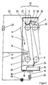
- Figure 1 shows schematically a washing compartment according to the invention.
- FIG. 2 shows a section of FIG. 1 on a larger scale.
- the washing compartment according to FIG. 1 is approximately 2.0 m high and 2.0 to 3.0 m long. It has a housing with a ceiling 1, a bottom 2 and with side walls that are parallel to the level of Figure 1.
- the structural design on the inlet side 3 and the outlet side 4 depends on the position of the washing compartment within the entire washing machine. It corresponds to the state of the art and belongs not to the invention. Therefore, another description is at this point dispensable.
- the inlet 3 first horizontal collecting container 10 has an overflow weir 11. This is arranged that excess washing liquid enters a drain 12 between the inlet-side collection container 10 and the adjacent collection container 10a an overflow weir 11a arranged between the collection container 10a and an overflow weir 11b behind the collecting container 10b.
- the Overflow weir 11a is perpendicular below that between the lower rollers 8, 7a existing gap arranged and aligned parallel to the lower rollers
- Das Overflow weir 11b is correspondingly under the gap between the Bottom rollers 8a, 7b arranged.
- the overflow weirs 11, 11a, 11b of the three Collecting containers 10, 10a, 10b are arranged in the manner of a staircase leading from the Inlet side 3 increases in the direction of the outlet side 4, so that a flow of Washing liquid from collection container to collection container only in the Goods run in the opposite direction is possible.
- Zones 13 are located vertically above the collecting containers 10, 10a, 10b, 13a, 13b of the washing compartment. Washer fluid that is in operation in zone 13 of the web drains, therefore, enters the collecting container 10, dripping Washing liquid from zones 13a and 13b into the collecting containers 10a and 10b, respectively.
- inlet-side zone 13 which is shown on a larger scale in FIG. 2, belong to the two top rollers 5, 6 and the two bottom rollers 7, 8.
- a pouring trough 14 is arranged, which one over the has the entire working width extending overflow edge 15.
- the overflow edge 15 is attached on the side facing the inlet, so that washing liquid, which flows out of the trough 14 over the overflow edge 15 into the gusset arrives, between the outer surface of the lower roller 7 and in the direction of Arrow 16 tapering run of the web 9 is formed.
- In the trough 14 opens a line 17 which is connected to the pressure side of a pump 18.
- the pump 18 On the suction side, the pump 18 is connected to the collecting container 10 through a line 19 connected.
- a filter 20 is located between the collecting container 10 and the pump 18 switched on.
- a spray nozzle 21 is located above the inlet-side upper roller 5 of zone 13 attached, which is directed radially to the top roller 5 and over the entire Working width extends. It is by an outgoing from line 17 Branch line 22 connected to the pressure side of the pump 18.
- the branch line 22 is equipped with a metering valve 23.
- a second spray nozzle 24 is under the Lower roller 8 arranged and directed radially on this - is similar to that Spray nozzle 21 - connected to line 17 via a branch line 25.
- top roller 5 On the inlet side, one is in the material flow in front of the spray nozzle 21 Steam nozzle 26 attached, which is connected to a steam line 27. about the other top roller 6 has a support roller 28 attached to it Swing arm 29 is mounted between the top roller 6 and the top roller 5a adjacent zone 13a there is a splash panel 30.
- Zones 13a and 13b are constructed completely analogously to zone 13
- the above description of the zone 13 reference numerals used in the corresponding parts of zones 13a, 13b the letter "a” or "b" been added. In order to avoid a confusing overloading of FIG. 1, numerous reference symbols have not been entered.
- Zone 13b is followed by an outlet zone 31 in which a trough is located on the floor 32 is arranged, as indicated by a broken line 33, be separated from the collecting container 10b by an overflow weir.
- the Overflow weir can also be missing, so that the trough 32 without separating Intermediate element forms a unit with the collecting container 10b.
- a Dip roller 34 is mounted in the trough 32 so that part of the outer surface located below the liquid level. So it is lower than the lower rollers 7, 8 ..., which are arranged at a distance above the collecting containers 10, 10a, 10b.
- a distribution channel 40 is attached above the dipping roller. She has on the side the web run between the upper roller 6b and the plunger roller 34 is facing an overflow edge, so that washing liquid that flows through a line 41 the distribution channel 40 is fed into the gusset between this Material web run and the outer surface of the plunger roller 34
- a flat jet nozzle 42 is arranged, which in the Space between the two deflection rollers is directed. She is with one Branch line 43 connected to line 41. Under the two deflection rollers 37, 38 a funnel 44 is arranged, the drain pipe 45 opens into the trough 32.
- a pipe socket 46 penetrates the bottom of the compartment. It is connected to an exhaust pipe, not shown.
- the web 9 arriving in the moist state initially comes along the washing liquid supplied from the trough 14 in contact.
- the Washing liquid is, as follows from the following, with a certain Concentration of washed-out impurities. However, that is Concentration significantly lower than the concentration of the liquid with which the incoming material web is impregnated by the difference in concentration there is a washing effect in such a way that the more contaminated liquid due to the supplied washing liquid, which Circulation of the lower roller 7 is pressed through the web, partially is ousted. Behind the lower roller 7 therefore has that of the web carried liquid a lower concentration than before. On the way to Top roller 5 arises through diffusion processes between the residues of the original moisture and the newly added washing liquid Concentration adjustment.
- the spray nozzle 21 Wash liquid applied to the web after this immediately beforehand for the purpose of intensifying the exchange processes through the steam nozzle 26 Steam has been applied.
- the one applied with the spray nozzle 21 Washing liquid runs on the web of material running towards the lower roller 8 below, rinsing the surface of the web. Then she gets in the gusset over the lower roller 8 and when the lower roller 8 rotates pushed through the web. At the same time, a flush is carried out additional washing liquid sprayed with the spray nozzle 24 from below becomes.
- Adhesive washing liquid runs partially on the way to the top roller 6 downwards. The remaining washing liquid is through the support roller 28 partially squeezed, so that only a relatively small amount in the subsequent Zone 13a is dragged along.
- the moisture carried along has one at this point Concentration that is well below the concentration of the original adherent Humidity. It is not much higher than the concentration in zone 13 used washing liquid
- zone 13a the material web is again used in a corresponding manner Wash liquid and steam treated, then also in zone 13b.
- the web is first in the trough 32 on the Dip roller 34 rinsed thoroughly.
- the deflection rollers 37, 38 is on the Material web with a slight slope from the top of the guide roller 37 to Underside of the deflection roller 38 runs, fresh, supplied from the outside Wash liquid sprayed on immediately after the circulation around the Deflection roller 38 and the outlet roller 39 is pressed through the goods.
- the washing liquid with which the goods in zone 13b has been treated largely pushed out of the goods and fresh Washer fluid replaced.
- a "fresh washing liquid” z. B. tap water or demineralized water can also be used.
- wash compartment in one consisting of several compartments connected in series Wide washing machine can also deliver the goods from a compartment following in the direction of the goods removed washing liquid can be supplied as "fresh washing liquid". It is essential that the concentration in the fresh washing liquid supplied of impurities is significantly lower than the desired concentration in the moisture still carried by the web at the outlet of zone 13b becomes.
- the fresh washing liquid supplied is only slightly in the outlet zone 31 Measure contaminated with impurities, since the web in this zone is already relatively is clean.
- zones 13b, 13a, 13 in which the washing liquid is pumped around and is brought into intensive contact with the web, enriches it Wash liquid gradually with impurities. In stationary operation there is an equilibrium concentration in each zone. It is the lower the more fresh washing liquid is added.
- the washing liquid becomes like this dosed that in each zone between the concentration of the washing liquid and the concentration of the liquid with which the web is loaded, one there is sufficient difference. The difference is decisive for the washing effect, not the absolute value of the concentration of the washing liquid.
- zone 13b the the outlet zone 31 is immediately upstream in the goods run, is therefore one relatively clean washing liquid required.
- zone 13b Because the one getting there Material path already go through several washing processes in zones 13, 13a has, the washing liquid is only slightly contaminated in zone 13b.
- the washing compartment according to the invention the carry-over of Contaminants from the previous zones 13, 13a into zone 13b is avoided. Therefore, in zone 13b with a relatively small supply of fresh washing liquid maintain the required low concentration.
- the weakly contaminated washing liquid in zone 13b passes through the Overflow weir 11b in the collecting container 10a and thus in the circuit of the zone 13a.
- the concentration of the liquid carried by the goods is still there high that despite the already increased concentration of those pumped around in the circuit Washing liquid still the necessary for the desired washing effect
- There is a concentration gradient. Maintaining the concentration gradient is made possible by the arrangement according to the invention, which converts from Washing liquid from zone 13 to zone 13a - apart from the small one Amount of washing liquid adhering to the goods - practically excludes. In In the corresponding way, the excess washing liquid comes out of the Zone 13a in the circulation of zone 13.
- There is the concentration gradient to that still relatively heavily contaminated liquid carried along by the web becomes sufficiently large to achieve the desired washing effect.
- a complete wide washing machine can e.g. B. be constructed in such a way that three washing compartments according to the invention are strung together. It is also possible and, depending on the requirements, for cost reasons be advantageous to have at least one washing compartment according to the invention with at least a conventional washing compartment, preferably according to the entry state of the art, to combine. Usually it is recommendable to use the washing compartment according to the invention, if inside of a single compartment a high initial concentration of that of the goods entrained moisture is significantly reduced. This is true in many Applications for the inlet-side compartment of a wide-range washing machine, sometimes also for an adjoining intermediate compartment. Behind it one can state-of-the-art outlet compartment discussed are used, if necessary, also one that is immediately upstream of the outlet compartment Intermediate compartment.
Landscapes
- Engineering & Computer Science (AREA)
- Textile Engineering (AREA)
- Treatment Of Fiber Materials (AREA)
- Detergent Compositions (AREA)
Description
Claims (15)
- Waschabteil einer aus mehreren baukastenartig aneinandergereihten Abteilen bestehenden Breitwaschmaschine mit folgenden Merkmalen:a) in einem Gehäuse reihenweise angeordnet sind Oberwalzen und Unterwalzen zum Führen der zu behandelnden Warenbahn in senkrechten oder annähernd senkrechten Schleifen;b) über mindestens zwei Unterwalzen befindet sich je ein Mittel zum Einleiten von Waschflüssigkeit in den Zwickel zwischen der Mantelfläche der Unterwalze und dem ihr zulaufenden Warenbahntrum;c) dem Waschabteil zugeordnet sind Einrichtungen zum Zuführen frischer Waschflüssigkeit, zum Auffangen der von der Warenbahn abtropfenden Waschflüssigkeit, zum Umpumpen aufgefangener Waschflüssigkeit im Kreislauf zurück zu den Mitteln zum Einleiten von Waschflüssigkeit und zum Ableiten überschüssiger Waschflüssigkeit;
gekennzeichnet durch folgende weitere Merkmale:d) unter den Unterwalzen (7, 8; 7a, 8a; 7b, 8b) befinden sich - in Warenlaufrichtung hintereinander angeordnet - mindestens zwei separate Sammelbehälter (10, 10a, 10b) zum Auffangen der in entsprechenden Zonen (13, 13a, 13b) des Waschabteils von der Warenbahn (9) abtropfenden Waschflüssigkeit;e) in jeder Zone (13, 13a, 13b) ist als Mittel zum Einleiten von Waschflüssigkeit über mindestens einer Unterwalze (7, 7a, 7b) eine Gießrinne (14, 14a, 14b) angeordnet;f) jeder einzelnen Zone (13, 13a, 13b) ist eine saugseitig mit einem Sammelbehälter (10, 10a, 10b) und druckseitig mit der Gießrinne (14, 14a, 14b) verbundene Pumpe (18, 18a, 18b) zugeordnet;g) zwischen den Sammelbehältern (10, 10a 10b) der benachbarten Zonen (13, 13a, 13b) besteht eine Verbindung (11a, 11b), welche einen Durchfluß von Waschflüssigkeit nur in der dem Warenlauf entgegengesetzten Richtung zuläßt. - Waschabteil nach Anspruch 1, dadurch gekennzeichnet, daß der Sammelbehälter (10) der dem Einlauf (3) benachbarten Zone (13) durch ein Überlaufwehr (11) mit einem Abfluß (12) in Verbindung steht
- Waschabteil nach Anspruch 1 oder 2, dadurch gekennzeichnet, daß zwischen den Sammelbehältern (10, 10a, 10b) je zweier benachbarter Zonen (13, 13a, 13b) ein Überlaufwehr (11a, 11b) angeordnet ist und daß die Überlaufwehre (11, 11a, 11b) nach Art einer in Warenlaufrichtung ansteigenden Treppe angeordnet sind.
- Waschabteil nach einem der Ansprüche 1 bis 3, dadurch gekennzeichnet, daß in jeder Zone (13, 13a, 13b) zwei Oberwalzen (5, 6; 5a, 6a; 5b, 6b) und zwei Unterwalzen (7, 8; 7a, 8a; 7b, 8b) angeordnet sind und daß die Gießrinne (14, 14a, 14b) über der dem Einlauf (3) zunächst liegenden Unterwalze (7, 7a, 7b) der Zone (13, 13a, 13b) angeordnet ist.
- Waschabteil nach Anspruch 4, dadurch gekennzeichnet, daß mindestens eine Zone (13, 13a, 13b) mit mindestens einer Spritzvorrichtung (21, 21a, 21b, 24, 24a, 24b) zum Aufspritzen von Waschflüssigkeit auf die Warenbahn (9) ausgestattet ist und daß die Spritzvorrichtung mit einer Leitung (22, 22a, 22b, 25, 25a, 25b) verbunden ist, die von der zur Gießrinne (14, 14a, 14b) dieser Zone führenden Leitung (17, 17a, 17b) abgezweigt ist
- Waschabteil nach Anspruch 5, dadurch gekennzeichnet, daß die Spritzvorrichtung (21, 21a, 21b, 24, 24a, 24b) im Warenlauf hinter der Gießrinne (14, 14a, 14b) angeordnet ist
- Waschabteil nach Anspruch 6, dadurch gekennzeichnet, daß eine Spritzvorrichtung (21, 21a, 21b) über der dem Einlauf (3) zunächstliegenden Oberwalze (5, 5a, 5b) angeordnet und annähernd radial zu dieser Oberwalze ausgerichtet ist.
- Waschabteil nach Anspruch 7, dadurch gekennzeichnet, daß im Warenlauf vor der Spritzvorrichtung (21, 21a, 21b) über der Oberwalze (5, 5a, 5b) eine Dampfdüse (26, 26a, 26b) angeordnet und annähernd radial zu dieser Oberwalze ausgerichtet ist
- Waschabteil nach einem der Ansprüche 5 bis 8, dadurch gekennzeichnet, daß eine Spritzvorrichtung (24, 24a, 24b) unter der dem Auslauf (4) zunächstliegenden Unterwalze (8, 8a, 8b) angeordnet und annähernd radial zu dieser Unterwalze ausgerichtet ist.
- Waschabteil nach einem der Ansprüche 4 bis 9, gekennzeichnet durch eine Auflagewalze (28, 28a, 28b) über der dem Auslauf (4) zunächstliegenden Oberwalze (6, 6a, 6b).
- Waschabteil nach einem der Ansprüche 1 bis 10, gekennzeichnet durch Trennbleche (30, 30a) zwischen den Oberwalzen (6, 5a; 6a, 5b) benachbarter Zonen (13, 13a, 13b).
- Waschabteil nach einem der Ansprüche 1 bis 11, dadurch gekennzeichnet, daß in einer Auslaufzone (31) in annähernd gleicher Höhe mit Abstand zwei Umlenkwalzen (37, 38) angeordnet sind, daß eine Flachstrahldüse (42), die an eine Leitung (43) zum Zuführen frischer Waschflüssigkeit angeschlossen ist, von oben in den Zwischenraum der beiden Umlenkwalzen (37, 38) gerichtet ist und daß darunter ein Trichter (44) angeordnet ist, von dem ein Abflußrohr (45) zu einem Trog (32) geführt ist
- Waschabteil nach Anspruch 12, dadurch gekennzeichnet, daß in dem Trog (32) - im Warenlauf den Umlenkwalzen (37, 38) vorgeschaltet - eine Tauchwalze (34) angeordnet ist
- Waschabteil nach Anspruch 13, gekennzeichnet durch eine über der Tauchwalze (34) angeordnete Verteilerrinne (40), die mit einer Frischwasserleitung (41) verbunden ist.
- Waschabteil nach einem der Ansprüche 12 bis 14, dadurch gekennzeichnet, daß der Trog (32) mit dem Sammelbehälter (10b) der dem Auslauf (4) zunächstliegenden Zone (13b) eine Einheit bildet.
Applications Claiming Priority (2)
| Application Number | Priority Date | Filing Date | Title |
|---|---|---|---|
| DE29708256U DE29708256U1 (de) | 1997-05-07 | 1997-05-07 | Waschabteil |
| DE29708256U | 1997-05-07 |
Publications (3)
| Publication Number | Publication Date |
|---|---|
| EP0877113A2 EP0877113A2 (de) | 1998-11-11 |
| EP0877113A3 EP0877113A3 (de) | 1999-10-13 |
| EP0877113B1 true EP0877113B1 (de) | 2003-05-28 |
Family
ID=8040103
Family Applications (1)
| Application Number | Title | Priority Date | Filing Date |
|---|---|---|---|
| EP98101798A Expired - Lifetime EP0877113B1 (de) | 1997-05-07 | 1998-02-03 | Waschabteil |
Country Status (3)
| Country | Link |
|---|---|
| EP (1) | EP0877113B1 (de) |
| DE (2) | DE29708256U1 (de) |
| ES (1) | ES2201345T3 (de) |
Families Citing this family (2)
| Publication number | Priority date | Publication date | Assignee | Title |
|---|---|---|---|---|
| DE10339020A1 (de) * | 2003-08-25 | 2005-03-24 | Fehring, Hannes, Dipl.-Ing. | Verfahren und Vorrichtung zur Reinigung von Segeln |
| CN114108290A (zh) * | 2021-11-24 | 2022-03-01 | 温州鑫洋机械有限公司 | 一种布料印染设备及其印染工艺 |
Family Cites Families (6)
| Publication number | Priority date | Publication date | Assignee | Title |
|---|---|---|---|---|
| DE2518770A1 (de) * | 1975-04-28 | 1976-11-11 | Vepa Ag | Nassbehandlungsvorrichtung fuer endlosmaterial |
| DE2834854C2 (de) * | 1978-08-09 | 1982-04-01 | Küsters, Eduard, 4150 Krefeld | Quetschwerklose Vorrichtung zum fortlaufenden Naßbehandeln, insbesondere Waschen von Textilgut |
| DE3511949A1 (de) * | 1985-04-02 | 1986-10-09 | Babcock Textilmaschinen GmbH, 2105 Seevetal | Verfahren und vorrichtung zur einsparung von wasser bei waschmaschinen |
| DE3831316A1 (de) * | 1987-11-20 | 1990-04-05 | Babcock Textilmasch | Vorrichtung zum wassersparenden waschen von laufenden warenbahnen |
| DE3739346A1 (de) * | 1987-11-20 | 1989-06-01 | Babcock Textilmasch | Verfahren und vorrichtung zum wassersparenden waschen von laufenden warenbahnen |
| ES2063088T3 (es) * | 1988-09-15 | 1995-01-01 | Babcock Textilmasch | Dispositivo para el lavado con ahorro de agua de bandas de genero en movimiento. |
-
1997
- 1997-05-07 DE DE29708256U patent/DE29708256U1/de not_active Expired - Lifetime
-
1998
- 1998-02-03 DE DE59808509T patent/DE59808509D1/de not_active Expired - Fee Related
- 1998-02-03 ES ES98101798T patent/ES2201345T3/es not_active Expired - Lifetime
- 1998-02-03 EP EP98101798A patent/EP0877113B1/de not_active Expired - Lifetime
Also Published As
| Publication number | Publication date |
|---|---|
| ES2201345T3 (es) | 2004-03-16 |
| DE59808509D1 (de) | 2003-07-03 |
| DE29708256U1 (de) | 1997-07-24 |
| EP0877113A2 (de) | 1998-11-11 |
| EP0877113A3 (de) | 1999-10-13 |
Similar Documents
| Publication | Publication Date | Title |
|---|---|---|
| EP0310826B1 (de) | Vorrichtung zur Zufuhr einer Flüssigkeit in einen länglichen Flüssigkeitsvorrat | |
| DE2848682A1 (de) | Holzpulpewaescher | |
| DE2707536A1 (de) | Vorrichtung zum aufbringen von fluessigkeit auf sich bewegendes material | |
| EP0316859B2 (de) | Verfahren und Vorrichtung zum wassersparenden Waschen von laufenden Warenbahnen | |
| DE2140612A1 (de) | Verfahren zur behandlung oder ausruestung von stoff und vorrichtung zur ausfuehrung des verfahrens | |
| DE3511949A1 (de) | Verfahren und vorrichtung zur einsparung von wasser bei waschmaschinen | |
| EP0877113A2 (de) | Waschabteil | |
| DE69021954T2 (de) | Vorrichtung zum kontinuierlichen Nassbehandeln von Geweben. | |
| EP0280924A1 (de) | Jigger | |
| DE2051478A1 (de) | Verfahren und Vorrichtung zum Reim gen von loser Rohwolle | |
| DE3137663A1 (de) | Verfahren und vorrichtung zum spuelen von textilgut | |
| DE2834854C2 (de) | Quetschwerklose Vorrichtung zum fortlaufenden Naßbehandeln, insbesondere Waschen von Textilgut | |
| DE3012612A1 (de) | Vorrichtung zum auswachsen durchlaessiger warenbahnen und verwendungen dieser vorrichtung | |
| DE4303753A1 (de) | Lackiereinrichtung | |
| EP0180938B1 (de) | Anordnung zum Aufbringen von Flüssigkeiten auf laufende Warenbahnen | |
| DE9413094U1 (de) | Behandlungsvorrichtung für eine textile Warenbahn | |
| DE8631105U1 (de) | Entwässerungsvorrichtung mittels Absaugung der Flüssigkeit | |
| EP1046738B1 (de) | Verfahren und Vorrichtung zum kontinuierlichen Waschen einer textilen Bahn | |
| DE69124658T2 (de) | Wascheinrichtung für ein Gewebe unbegrenzter Länge | |
| DE2521600A1 (de) | Nassbehandlungsvorrichtung fuer auf laengszug beanspruchbares endlosmaterial | |
| DE8001334U1 (de) | Vorrichtung zum aufbringen eines faerbefluessigkeitsfilmes auf eine warenbahn | |
| DE1460357C3 (de) | Vorrichtung zum Naßbehandeln von Fasermaterialien | |
| DE19729205C2 (de) | Vakuumbandfilteranlage, insbesondere zur Trennung von Feststoff-Flüssigkeits-Suspensionen | |
| DE3831316A1 (de) | Vorrichtung zum wassersparenden waschen von laufenden warenbahnen | |
| DE1460347C3 (de) | Vorrichtung zur kontinuierKchen Behandlung von bahnförmigem Textilgut mit Flüssigkeit |
Legal Events
| Date | Code | Title | Description |
|---|---|---|---|
| PUAI | Public reference made under article 153(3) epc to a published international application that has entered the european phase |
Free format text: ORIGINAL CODE: 0009012 |
|
| AK | Designated contracting states |
Kind code of ref document: A2 Designated state(s): CH DE ES GB IT LI NL |
|
| AX | Request for extension of the european patent |
Free format text: AL;LT;LV;MK;RO;SI |
|
| PUAL | Search report despatched |
Free format text: ORIGINAL CODE: 0009013 |
|
| AK | Designated contracting states |
Kind code of ref document: A3 Designated state(s): AT BE CH DE DK ES FI FR GB GR IE IT LI LU MC NL PT SE |
|
| AX | Request for extension of the european patent |
Free format text: AL;LT;LV;MK;RO;SI |
|
| 17P | Request for examination filed |
Effective date: 20000413 |
|
| AKX | Designation fees paid |
Free format text: CH DE ES GB IT LI NL |
|
| 17Q | First examination report despatched |
Effective date: 20020724 |
|
| GRAH | Despatch of communication of intention to grant a patent |
Free format text: ORIGINAL CODE: EPIDOS IGRA |
|
| RAP1 | Party data changed (applicant data changed or rights of an application transferred) |
Owner name: BTM TEXTILMASCHINEN GMBH |
|
| GRAH | Despatch of communication of intention to grant a patent |
Free format text: ORIGINAL CODE: EPIDOS IGRA |
|
| GRAA | (expected) grant |
Free format text: ORIGINAL CODE: 0009210 |
|
| AK | Designated contracting states |
Designated state(s): CH DE ES GB IT LI NL |
|
| REG | Reference to a national code |
Ref country code: GB Ref legal event code: FG4D Free format text: NOT ENGLISH |
|
| REG | Reference to a national code |
Ref country code: CH Ref legal event code: EP |
|
| REF | Corresponds to: |
Ref document number: 59808509 Country of ref document: DE Date of ref document: 20030703 Kind code of ref document: P |
|
| REG | Reference to a national code |
Ref country code: CH Ref legal event code: NV Representative=s name: BOVARD AG PATENTANWAELTE |
|
| GBT | Gb: translation of ep patent filed (gb section 77(6)(a)/1977) |
Effective date: 20031015 |
|
| REG | Reference to a national code |
Ref country code: ES Ref legal event code: FG2A Ref document number: 2201345 Country of ref document: ES Kind code of ref document: T3 |
|
| PLBE | No opposition filed within time limit |
Free format text: ORIGINAL CODE: 0009261 |
|
| STAA | Information on the status of an ep patent application or granted ep patent |
Free format text: STATUS: NO OPPOSITION FILED WITHIN TIME LIMIT |
|
| 26N | No opposition filed |
Effective date: 20040302 |
|
| REG | Reference to a national code |
Ref country code: CH Ref legal event code: PUE Owner name: MOENUS TEXTILMASCHINEN GMBH Free format text: BTM TEXTILMASCHINEN GMBH#BLUMENBERGER STRASSE 143-145#41061 MAENCHENGLADBACH (DE) -TRANSFER TO- MOENUS TEXTILMASCHINEN GMBH#HEINRICH-HERTZ-STRASSE 28#07552 GERA (DE) |
|
| PGFP | Annual fee paid to national office [announced via postgrant information from national office to epo] |
Ref country code: ES Payment date: 20060216 Year of fee payment: 9 |
|
| PGFP | Annual fee paid to national office [announced via postgrant information from national office to epo] |
Ref country code: NL Payment date: 20060228 Year of fee payment: 9 |
|
| PGFP | Annual fee paid to national office [announced via postgrant information from national office to epo] |
Ref country code: CH Payment date: 20070208 Year of fee payment: 10 |
|
| PGFP | Annual fee paid to national office [announced via postgrant information from national office to epo] |
Ref country code: DE Payment date: 20070222 Year of fee payment: 10 |
|
| GBPC | Gb: european patent ceased through non-payment of renewal fee |
Effective date: 20070203 |
|
| NLV4 | Nl: lapsed or anulled due to non-payment of the annual fee |
Effective date: 20070901 |
|
| PGFP | Annual fee paid to national office [announced via postgrant information from national office to epo] |
Ref country code: IT Payment date: 20070503 Year of fee payment: 10 |
|
| PG25 | Lapsed in a contracting state [announced via postgrant information from national office to epo] |
Ref country code: NL Free format text: LAPSE BECAUSE OF NON-PAYMENT OF DUE FEES Effective date: 20070901 |
|
| PG25 | Lapsed in a contracting state [announced via postgrant information from national office to epo] |
Ref country code: GB Free format text: LAPSE BECAUSE OF NON-PAYMENT OF DUE FEES Effective date: 20070203 |
|
| REG | Reference to a national code |
Ref country code: ES Ref legal event code: FD2A Effective date: 20070205 |
|
| PG25 | Lapsed in a contracting state [announced via postgrant information from national office to epo] |
Ref country code: ES Free format text: LAPSE BECAUSE OF NON-PAYMENT OF DUE FEES Effective date: 20070205 |
|
| REG | Reference to a national code |
Ref country code: CH Ref legal event code: PL |
|
| PG25 | Lapsed in a contracting state [announced via postgrant information from national office to epo] |
Ref country code: LI Free format text: LAPSE BECAUSE OF NON-PAYMENT OF DUE FEES Effective date: 20080229 Ref country code: CH Free format text: LAPSE BECAUSE OF NON-PAYMENT OF DUE FEES Effective date: 20080229 |
|
| PGFP | Annual fee paid to national office [announced via postgrant information from national office to epo] |
Ref country code: GB Payment date: 20060206 Year of fee payment: 9 |
|
| PG25 | Lapsed in a contracting state [announced via postgrant information from national office to epo] |
Ref country code: DE Free format text: LAPSE BECAUSE OF NON-PAYMENT OF DUE FEES Effective date: 20080902 |
|
| PG25 | Lapsed in a contracting state [announced via postgrant information from national office to epo] |
Ref country code: IT Free format text: LAPSE BECAUSE OF NON-PAYMENT OF DUE FEES Effective date: 20080203 |