EP0875873B1 - Capteur opto-électronique - Google Patents
Capteur opto-électronique Download PDFInfo
- Publication number
- EP0875873B1 EP0875873B1 EP98107138A EP98107138A EP0875873B1 EP 0875873 B1 EP0875873 B1 EP 0875873B1 EP 98107138 A EP98107138 A EP 98107138A EP 98107138 A EP98107138 A EP 98107138A EP 0875873 B1 EP0875873 B1 EP 0875873B1
- Authority
- EP
- European Patent Office
- Prior art keywords
- light
- accordance
- optoelectronic sensor
- receiver
- sensor
- Prior art date
- Legal status (The legal status is an assumption and is not a legal conclusion. Google has not performed a legal analysis and makes no representation as to the accuracy of the status listed.)
- Expired - Lifetime
Links
Images

Classifications
-
- G—PHYSICS
- G08—SIGNALLING
- G08B—SIGNALLING SYSTEMS, e.g. PERSONAL CALLING SYSTEMS; ORDER TELEGRAPHS; ALARM SYSTEMS
- G08B13/00—Burglar, theft or intruder alarms
- G08B13/18—Actuation by interference with heat, light, or radiation of shorter wavelength; Actuation by intruding sources of heat, light, or radiation of shorter wavelength
- G08B13/181—Actuation by interference with heat, light, or radiation of shorter wavelength; Actuation by intruding sources of heat, light, or radiation of shorter wavelength using active radiation detection systems
- G08B13/183—Actuation by interference with heat, light, or radiation of shorter wavelength; Actuation by intruding sources of heat, light, or radiation of shorter wavelength using active radiation detection systems by interruption of a radiation beam or barrier
-
- G—PHYSICS
- G01—MEASURING; TESTING
- G01V—GEOPHYSICS; GRAVITATIONAL MEASUREMENTS; DETECTING MASSES OR OBJECTS; TAGS
- G01V8/00—Prospecting or detecting by optical means
- G01V8/10—Detecting, e.g. by using light barriers
- G01V8/12—Detecting, e.g. by using light barriers using one transmitter and one receiver
- G01V8/14—Detecting, e.g. by using light barriers using one transmitter and one receiver using reflectors
Definitions
- the invention relates to an optoelectronic sensor a light transmitter for sending light signals into one Monitoring area and a light receiver for reception of the light signals emitted by the light transmitter, one Evaluation circuit acted upon directly or indirectly by the light receiver for generating an object detection signal in the event of the presence of an object in the surveillance area is provided.
- Such sensors are used, for example, as simple light barriers or multi-beam light curtain systems for access monitoring used, especially dangerous Machine work areas or specific rooms within of a building are to be secured.
- an object in the monitoring area arrives and thus the light path between Interrupts the light transmitter and light receiver, an object detection signal generated, for example to switch off a machine or to trigger a acoustic or optical warning process.
- the decision is based on whether the light path between transmitter and receiver is interrupted or not, usually on a purely energetic basis, which means that whenever the received Amount of light falls below a certain value to which Interruption of the light path and thus the presence of an object in the surveillance area is closed.
- the problem with known systems is the fact that reflective objects within certain use cases the transmission angle of the light transmitter or within the Field of view of the light receiver can be arranged, which are generally permissible, i.e. no object detection signal should trigger, but can lead to that an impermissible object reflects in the surveillance area becomes.
- the central light beam between light transmitter and Light receiver interrupted by an impermissible object be, however, by the specified permissible reflective Objects still directed as much light onto the light receiver be that the critical light quantity value is not undercut and consequently also the generation of an object detection signal omitted.
- the known sensors can therefore not be guaranteed that everyone in the surveillance area existing impermissible objects reliably can be detected.
- An object of the invention is an opto-electronic To further develop sensors of the type mentioned at the outset, that its reliability is increased, in particular the disruptive influence of allowable reflective Objects near the surveillance area or in the surveillance area itself should be eliminated.
- the Light receiver as a spatially resolving receiving element for determination the position of the reception light center in the area the photosensitive surface of the receiving element is that a cooperating with the evaluation circuit Storage element for storing at least one target position of the receiving light center of gravity is provided, and that the evaluation circuit means for comparison during of the operation of the sensor determined actual positions with a stored target position, wherein an object detection signal can be generated for the case in which the deviation of the actual position from the target position one exceeds the defined threshold.
- the spatially resolving Receiving element is designed so that the position of the Focus of reception on the light-sensitive surface can be determined.
- a target position is specified, which during operation of the sensor according to the invention with the determined actual positions is compared.
- the detection is therefore in accordance with the principle of the invention of an impermissible object in the surveillance area also possible if near the surveillance area or permitted in the surveillance area itself reflective objects are arranged so that a significant Proportion of the amount of light emitted by the light transmitter even if the central light beam is interrupted by a prohibited object is directed to the light receiver, i.e. if the permissible objects reflect the impermissible Lead object.
- the reliability of the invention Sensors is therefore compared to the prior art known sensors significantly improved.
- the spatially resolving receiving element from a row arrangement of several photosensitive Elements.
- several to provide photosensitive elements in a matrix arrangement this matrix then being the light sensitive area of the whole Forms reception elements.
- a row arrangement i.e. of a one-dimensional receiving element
- such reflections are detected or eliminated, which take place within a level that is at least in the essentially parallel to the row arrangement of the Receiving element forming photosensitive elements extends.
- any reflections are detected or eliminated, which are in any plane, which are parallel runs to the optical axis of the overall sensor system.
- the individual photosensitive elements of a row or Matrix arrangements can be used, for example, as photodiodes or as other elements suitable for the detection of light signals be trained.
- the invention provided spatially resolving receiving element as one or two-dimensional PSD, i.e. as a position sensitive detector train.
- a position sensitive detector is an electro-optical one Element with a photosensitive surface, the detector delivering two currents, for example whose amplitude ratio relates to that related to a dimension Position of a light spot on the photosensitive surface of the PSD. If one is delivering four streams PSD can be used from the amplitude ratio these flows towards each other on the two. Dimensions related Position of a light spot on the photosensitive Area of the PSD.
- a target position of the Receive light center using a teach-in process can be determined and saved.
- the sensor according to the invention individually to the respective Given the conditions of use.
- the target position to be saved in the frame of the teach-in process is determined such that a light signal in the monitoring area free of impermissible objects is sent out and received again, sets the position of the light spot caused by this light signal the photosensitive surface to the individual Coordinated setpoint.
- the end user of the sensor according to the invention is thus by means of the Teach-in process capable of individual To adapt to the respective operating conditions, without these operating conditions already during the manufacturing process of the sensor must be taken into account. this makes possible most diverse uses of the invention trained sensor.
- the spatially resolving receiving element of the sensor can be in the range the focal point of an imaging optical system be, here in particular due to the the aforementioned teach-in procedure given the learning ability of the Sensors do not exactly comply with the exact position of the receiving element in the focus must be observed. It it is entirely conceivable that the spatially resolving receiving element with regard to the imaging optics also intra- or is arranged extrafocal.
- the light transmitter and light receiver can face each other Sides of the surveillance area.
- the latter variant corresponds to one Auto-collimation.
- the sensor according to the invention can also be used in the context of a light grid arrangement are used, here one each A plurality of light transmitters and arranged side by side Light receivers arranged in the required structure become.
- the light receivers of the light grid arrangement are preferred formed as one-dimensional receiving elements.
- This one-dimensional Receiving elements can be arranged rotated relative to one another be, the axis of rotation corresponding to that axis, which mutually associated light transmitter and light receiver -Interconnecting. It is advantageous if the angle of twist between adjacent receiving elements Is 90 °. In this way is an inventive Light curtain assembly capable of any reflections to detect or eliminate that in any Plane, which are parallel to the mentioned axes of rotation runs. So although only one-dimensional Receiving elements can be used due to the described distortion eliminates any reflections become.
- a method for operating a sensor can have one or more target positions to be saved -
- - can be determined by the sensor on site under conditions of use with object-free Surveillance area is operated.
- the surveillance area However, reflective objects can be used here when determining the target position there are no illegal objects. If Different operating conditions possible at one location a setpoint for each of these operating conditions can be determined and saved, the different target positions, for example by means of of a selector switch can be activated. Alternative is it is also possible to save all stored target positions at the same time to activate, so that only an object detection signal is given when the actual position of all determined target positions in a given one Dimension deviates.
- the actual and target positions can be in the form of one dimension representative values or in the form of two dimensions representative coordinate values determined and processed become.
- the presence of the spatially resolving Reception elements are also used to make the inevitable Compensate opto-mechanical system tolerances for light grids.
- Such system tolerances are limited, for example by the torsion of those used for light curtains Fastening profiles, through wedge defects in lenses, through decentred positions of diaphragms, etc.
- To the compensation mentioned to effect is carried out as part of a calibration process the target position for each spatially resolving receiving element determined separately and, for example, together with an associated one permissible displacement tolerance. So lets achieve that the light curtain system according to the invention the existing requirements according to the safety standard of the swivel angle met and at the same time a maximum Adjustment range for the end user.
- an object detection signal is delivered whenever either the deviation of the determined actual position from the stored target position exceeds the defined threshold or if the amount of light received by the light receiver falls below a defined minimum value.
- an object detection signal to generate, because in this case the light receiver received light quantity a defined minimum value below.
- a light transmitter 1 designed as an LED, which emits a light cone in the direction of a transmission optics 2.
- the optical axis 3 of the transmission optics 2 coincides with the optical axis of a receiving optics 4 together, on the the side facing away from the transmission optics 2 is a PSD Light receiver 5 is provided.
- the surveillance area 6. Located between the transmitting optics 2 and the receiving optics 4 the surveillance area 6..
- the spatially resolving light receiver 5 delivers a position dependent signal on the light spot hitting it to an evaluation circuit 7, which has a memory element 8 for storing a target position and with a Means 9 for comparing the target position with a determined one Actual position is equipped.
- the transmission optics 2 bundle that emitted by the light transmitter 1 Light such that much of this light is parallel to the optical axis 3 is directed to the receiving optics 4. On However, part of the light emitted by light transmitter 1 becomes radiated at an angle to the optical axis 3 and thus arrives not on the receiving optics 4. This fact is over the arrows drawn in Fig. 1 can be seen which illustrate the light paths described.
- This target position is therefore suitable for a target position of the imaged on the light receiver 5 Determine light spots, this target position being the zero position 10 corresponds.
- This target position can be in the storage element 8 of the evaluation circuit 7 are stored, so that they are available for later comparison with actual positions stands.
- Fig. 2 shows the arrangement according to FIG. 1, with additional here below the monitoring area 6 a permissible reflective object 11 is present; its reflective Surface extends parallel to the optical axis 3 and is facing the surveillance area 6.
- the arrows shown in Fig. 2 illustrate that a Part of the light emitted by light transmitter 1 onto the reflective surface of the permissible reflective object 11 strikes and from there reaches the receiving optics 4.
- the receiving optics 4 bundles that from the permissible reflecting object 11 reflected light such that on the photosensitive surface of the light receiver 5 a second Light spot occurs at the position marked with 12, which is spaced from the zero position 10.
- the evaluation circuit 7 is able to the center the light intensity of the two at the zero position 10 and to calculate the light spots located at position 12. In this calculation go to both the positions of the two Light spots as well as those in the area of the two light spots each received amount of light. It follows a distance X of the center of light intensity thus averaged from the zero position 10. The distance X is smaller than the distance of position 12 from zero position 10.
- the distance X thus indicates a target position of the Sum of the received light spots under the operating conditions 2 with an allowable reflective object 11 near the surveillance area 6. It is possible this target value in addition to that determined according to FIG. 1 Store the setpoint as a further setpoint. It is the same possible to save only the target value determined according to FIG. 2. If two setpoints are saved, they are generated an object detection signal always if the determined actual value deviates from both setpoints.
- FIG. 3 shows the arrangement according to FIG. 2 with the difference, that an illegal object 13 is now in the monitoring area 6 is present, which is optically opaque and prevents that light from the transmission optics 2 parallel to the optical Axis 3 arrives at the receiving optics 4.
- the center of the light intensity is thus regarding its Position coincide with position 12, which is the location of the one Light spot describes which by the reflecting caused on the permissible reflecting object 11 becomes.
- the center of the light intensity points accordingly 3 shows a distance Z from the zero position 10, which is different from the distance X according to FIG. 2.
- the actual position can be compared be found that the deviation Z is not a setpoint corresponds, so that the presence of an object or an impermissible object in the monitoring area 6 is closed can be.
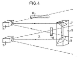
- Light transmitter 14 and light receiver 15 are on one side of a surveillance area 6 arranged while on the opposite side of the Monitoring area 6 a retroreflector 16 is provided, which has two mirrors 17, 18 which deflect the light beam emitted by the light transmitter 14 back to the light receiver 15 effect.
- a retroreflector 16 can be provided instead of the retroreflector 16 can a triple mirror system can also be provided.
- the surveillance area 6 there is a permissible reflective one Object 19 arranged. Above the surveillance area 6 a further permissible reflecting object 20 is arranged.
- Both reflecting objects 19, 20 cause a shift the center of those determined by the light receiver 15 Light intensity or a shift in the received light center.
- the position of the determined according to FIG. 4 The center of gravity is saved as the setpoint. If at Operation of the arrangement of FIG. 4 is an impermissible reflective or optically opaque object in the surveillance area 6 is introduced, this causes a shift of the light center, which ultimately leads to generation of an object detection signal.
Landscapes
- Physics & Mathematics (AREA)
- General Physics & Mathematics (AREA)
- Life Sciences & Earth Sciences (AREA)
- General Life Sciences & Earth Sciences (AREA)
- Geophysics (AREA)
- Geophysics And Detection Of Objects (AREA)
- Length Measuring Devices By Optical Means (AREA)
- Burglar Alarm Systems (AREA)
Claims (18)
- Capteur opto-électronique comportant un émetteur de lumière (1, 14) destiné à l'émission de signaux lumineux dans une zone de surveillance (6) ainsi qu'un récepteur de lumière (5, 15) réalisé comme élément récepteur à résolution spatiale et destiné à la réception des signaux lumineux émis par l'émetteur de lumière (1, 14), un circuit d'analyse (7) alimenté directement ou indirectement par le récepteur de lumière (5, 15) et permettant de générer un signal de constatation d'objet dans le cas de la présence d'un objet (13) dans la zone de surveillance (6) étant alors prévu, caractérisé en ce que le récepteur de lumière (5, 15) est conçu pour déterminer la position du point central de lumière de réception dans la zone de la surface sensible à la lumière de l'élément récepteur,
en ce qu'il est prévu un élément de mémoire (8) coopérant avec le circuit d'analyse (7) pour mémoriser au moins une position de consigne du point central de lumière de réception et
en ce que le circuit d'analyse (7) présente des moyens (9) pour la comparaison des positions réelles déterminées pendant le fonctionnement du capteur avec une position de consigne mémorisée, un signal de constatation d'objet pouvant être généré dans le cas où l'écart entre la position réelle et la position de consigne dépasse une valeur seuil définie. - Capteur opto-électronique selon la revendication 1, caractérisé en ce que l'élément récepteur (5, 15) à résolution spatiale comporte un agencement horizontal de plusieurs éléments sensibles à la lumière.
- Capteur opto-électronique selon la revendication 1, caractérisé en ce que l'élément récepteur (5, 15) à résolution spatiale comporte un agencement matriciel de plusieurs éléments sensibles à la lumière.
- Capteur opto-électronique selon l'une quelconque des revendications précédentes, caractérisé en ce que les éléments sensibles à la lumière sont réalisés sous forme de photodiodes.
- Capteur opto-électronique selon l'une quelconque des revendications 1 à 3, caractérisé en ce que l'élément récepteur (5, 15) à résolution spatiale est réalisé sous forme de détecteur PSD unidimensionnel ou bidimensionnel (détecteur de position).
- Capteur opto-électronique selon l'une quelconque des revendications précédentes, caractérisé en ce qu'une position de consigne du point central de lumière de réception peut être déterminée et mémorisée à l'aide de la méthode dite de l'apprentissage direct.
- Capteur opto-électronique selon l'une quelconque des revendications précédentes, caractérisé en ce que l'élément récepteur (5, 15) à résolution spatiale est disposé dans la zone du foyer d'un collecteur de lumière (4) de reproduction.
- Capteur opto-électronique selon l'une quelconque des revendications 1 à 6, caractérisé en ce que l'élément récepteur (5, 15) à résolution spatiale est disposé dans un plan intrafocal ou extrafocal par rapport à un collecteur de lumière de reproduction.
- Capteur opto-électronique selon l'une quelconque des revendications précédentes, caractérisé en ce que l'émetteur de lumière (1) et le récepteur de lumière (5) sont disposés sur des côtés opposés de la zone de surveillance (6).
- Capteur opto-électronique selon l'une quelconque des revendications 1 à 8, caractérisé en ce que l'émetteur de lumière (14) et le récepteur de lumière (15) sont disposés sur un côté de la zone de surveillance (6) et en ce qu'un rétroréflecteur (16) est disposé sur le côté opposé de la zone de surveillance (6).
- Capteur opto-électronique selon l'une quelconque des revendications précédentes, caractérisé en ce que plusieurs émetteurs de lumière (1, 14) et récepteurs de lumière (5, 15), selon l'une quelconque des revendications précédentes, sont prévus dans un agencement de grille lumineuse.
- Capteur opto-électronique selon la revendication 11, caractérisé en ce que les récepteurs de lumière (5, 15) de l'agencement de grille lumineuse sont réalisés sous forme d'éléments récepteurs unidimensionnels qui sont respectivement disposés l'un vers l'autre de façon à pivoter autour de l'axe assemblant l'un avec l'autre des émetteurs de lumière et des récepteurs de lumière.
- Capteur opto-électronique selon la revendication 12, caractérisé en ce que l'angle de pivotement entre des éléments récepteurs adjacents est de 90 °.
- Procédé d'exploitation d'un capteur opto-électronique selon l'une quelconque des revendications précédentes, caractérisé en ce qu'une position de consigne devant être mémorisée est déterminée tandis que le capteur est utilisé sur le lieu d'intervention dans des conditions d'utilisation de zone de surveillance (6) sans objet.
- Procédé d'exploitation d'un capteur opto-électronique selon l'une quelconque des revendications précédentes, caractérisée en ce que les positions réelles et de consigne sont déterminées et traitées sous forme de valeurs représentant une dimension ou sous forme de valeurs de coordonnées représentant deux dimensions.
- Procédé d'exploitation d'un capteur opto-électronique selon l'une quelconque des revendications précédentes, caractérisée en ce que, lors de l'utilisation d'un élément récepteur (PSD) délivrant au moins deux courants partiels identifiant la position du point central de lumière de réception, le quotient d'un courant partiel et du courant total des courant partiels est traité comme une grandeur identifiant la position déterminée.
- Procédé d'exploitation d'un capteur opto-électronique selon l'une quelconque des revendications précédentes, caractérisée en ce que, en cas d'utilisation d'une pluralité d'émetteurs de lumière (1, 14) et de récepteurs de lumière (85, 15) dans un agencement de grille lumineuse, un déplacement régulier des points centraux de lumière de réception de tous les récepteurs de lumière (5, 15) est classé comme écart admissible du système ou comme vibration à basse fréquence admissible et, par conséquent, ne déclenche pas de signal de constatation d'objet.
- Procédé d'exploitation d'un capteur opto-électronique selon l'une quelconque des revendications précédentes, caractérisée en ce qu'un signal de constatation d'objet est émis quand l'écart entre la position réelle déterminée et la position de consigne mémorisée dépassent le seuil de valeur défini ou quand la quantité de lumière reçue par le récepteur de lumière (5, 15) diminue au-dessous d'une valeur minimale définie.
Applications Claiming Priority (2)
| Application Number | Priority Date | Filing Date | Title |
|---|---|---|---|
| DE19718390 | 1997-04-30 | ||
| DE19718390A DE19718390A1 (de) | 1997-04-30 | 1997-04-30 | Opto-elektronischer Sensor |
Publications (3)
| Publication Number | Publication Date |
|---|---|
| EP0875873A1 EP0875873A1 (fr) | 1998-11-04 |
| EP0875873B1 true EP0875873B1 (fr) | 2003-09-24 |
| EP0875873B2 EP0875873B2 (fr) | 2012-12-12 |
Family
ID=7828301
Family Applications (1)
| Application Number | Title | Priority Date | Filing Date |
|---|---|---|---|
| EP98107138A Expired - Lifetime EP0875873B2 (fr) | 1997-04-30 | 1998-04-20 | Capteur opto-électronique |
Country Status (4)
| Country | Link |
|---|---|
| US (1) | US6023335A (fr) |
| EP (1) | EP0875873B2 (fr) |
| JP (1) | JP4108180B2 (fr) |
| DE (2) | DE19718390A1 (fr) |
Cited By (4)
| Publication number | Priority date | Publication date | Assignee | Title |
|---|---|---|---|---|
| EP1927868A2 (fr) | 2006-11-29 | 2008-06-04 | Sick Ag | Capteur optoélectrique |
| EP1947481A2 (fr) | 2007-01-20 | 2008-07-23 | Sick Ag | Capteur optoélectronique et procédé de saisie d'objets dans une zone de surveillance |
| EP2226652A1 (fr) | 2009-03-02 | 2010-09-08 | Sick Ag | Capteur optoélectronique doté d'un émetteur à lampe d'orientation |
| EP3324217A1 (fr) * | 2016-11-21 | 2018-05-23 | Sick AG | Capteur optique et procédé de surveillance d'une zone de surveillance |
Families Citing this family (9)
| Publication number | Priority date | Publication date | Assignee | Title |
|---|---|---|---|---|
| DE19933641A1 (de) * | 1999-07-17 | 2001-03-08 | Bosch Gmbh Robert | Sensoreinrichtung zur Erfassung einer Benetzung auf einer Scheibe |
| DE10142362A1 (de) | 2001-08-30 | 2003-03-27 | Sick Ag | Optoelekronische Überwachungseinrichtung |
| DE10143505B4 (de) * | 2001-09-05 | 2010-07-08 | Sick Ag | Sicherungsverfahren und optoelektronischer Sensor |
| ATE518220T1 (de) | 2006-09-29 | 2011-08-15 | Sick Ag | Optoelektronisches sicherheitssystem |
| DE102007023101A1 (de) | 2007-05-16 | 2008-11-20 | Sick Ag | Optoelektronische Sensoranordnung und Verfahren zur Überwachung eines Überwachungsbereiches |
| EP2083209B1 (fr) * | 2008-01-28 | 2012-10-17 | Sick Ag | Système de sécurité destiné à la mesure sans contact de voies et/ou de vitesses |
| DE102008029467A1 (de) * | 2008-06-20 | 2009-12-24 | Osram Opto Semiconductors Gmbh | Halbleiterbauelement, Verwendung eines Halbleiterbauelements als Näherungssensor sowie Verfahren zum Detektieren von Objekten |
| US10402834B2 (en) | 2009-09-30 | 2019-09-03 | Verizon Patent And Licensing Inc | Advertisements within television advertisements |
| DE102014111694A1 (de) * | 2014-08-15 | 2016-02-18 | Fraba B.V | Vorrichtung zur Überwachung einer Maschinenbewegung und Verfahren zum Überwachen einer Maschinenbewegung |
Family Cites Families (23)
| Publication number | Priority date | Publication date | Assignee | Title |
|---|---|---|---|---|
| DE2526001A1 (de) * | 1975-06-11 | 1976-12-23 | Precitec Gmbh | Lichtschranken-anordnung |
| DE2816324C2 (de) * | 1978-04-14 | 1983-06-23 | Siemens AG, 1000 Berlin und 8000 München | Verfahren und Vorrichtung zur automatischen Lageerkennung von Halbleiterchips |
| DE3213625C2 (de) * | 1982-04-13 | 1985-12-19 | Siemens AG, 1000 Berlin und 8000 München | Optischer Sensor |
| DE3513671C3 (de) † | 1985-04-16 | 1995-03-23 | Sick Optik Elektronik Erwin | Lichttaster |
| DE3532197A1 (de) * | 1985-09-10 | 1987-03-12 | Leuze Electronic Gmbh & Co | Lichtvorhang |
| US4903009A (en) * | 1988-05-18 | 1990-02-20 | Eastman Kodak Company | Intrusion detection device |
| GB2221294B (en) * | 1988-07-26 | 1993-03-03 | Formula Systems Ltd | Detection circuitry |
| DE4040225C2 (de) † | 1990-12-15 | 1994-01-05 | Leuze Electronic Gmbh & Co | Reflexions-Lichttaster |
| DE9104172U1 (de) † | 1991-04-06 | 1991-07-18 | Leuze electronic GmbH + Co, 7311 Owen | Retroreflektor |
| DE4119797C2 (de) * | 1991-06-15 | 1994-02-24 | Leuze Electronic Gmbh & Co | Einen Sender, einen Empfänger und eine Schaltungsanordnung zur Signalauswertung aufweisende Überwachungseinrichtung |
| DE4215272C2 (de) * | 1991-06-15 | 1994-11-17 | Leuze Electronic Gmbh & Co | Einen Sender, einen Empfänger und eine Schaltungsanordnung zur Signalauswertung aufweisende lichtelektrische Überwachungseinrichtung |
| DE4120630C1 (fr) * | 1991-06-22 | 1992-11-05 | Man Roland Druckmaschinen Ag, 6050 Offenbach, De | |
| ZA929406B (en) * | 1992-03-04 | 1993-09-27 | Csir | Monitoring system |
| DE4219260C2 (de) * | 1992-06-12 | 1994-07-14 | Leuze Electronic Gmbh & Co | Lichtelektrische Vorrichtung mit einem Testobjekt |
| JP3365799B2 (ja) * | 1992-11-24 | 2003-01-14 | オリンパス光学工業株式会社 | 距離・速度測定装置 |
| DE9301889U1 (de) * | 1993-02-08 | 1993-04-01 | Velox - Automation GmbH, O-8291 Brauna | Vorrichtung zur Erkennung, Lagebestimmung und zwei- oder dreidimensionalen Vermessung bewegter, flächenhafter Gegenstände |
| DE4338978C2 (de) * | 1993-11-15 | 1998-05-07 | Sick Ag | Verfahren zur Feststellung defekter Lichtsender und/oder Lichtempfänger eines Lichtgitters und Lichtgitter |
| DE4405376C1 (de) * | 1994-02-19 | 1995-02-16 | Leuze Electronic Gmbh & Co | Verfahren zum Erfassen von Objekten in einem Überwachungsbereich |
| DE4415944C2 (de) * | 1994-05-05 | 1998-07-09 | Karl Stefan Riener | Elektronische Zielscheibe und Verfahren zu dessen Auswertung |
| JP3254928B2 (ja) * | 1994-09-12 | 2002-02-12 | 日産自動車株式会社 | レーダ用位置検出センサおよびこれを用いたレーダ |
| DE19507812A1 (de) * | 1995-03-06 | 1996-09-12 | Marinitsch Waldemar | Verfahren und Vorrichtung zum Identifizieren und Lokalisieren eines Objektes |
| DE19544632A1 (de) * | 1995-11-30 | 1997-06-05 | Leuze Electronic Gmbh & Co | Optoelektronische Vorrichtung zum Erfassen von Objekten in einem Überwachungsbereich |
| DE19548578C2 (de) * | 1995-12-27 | 2001-02-08 | Elbau Elektronik Bauelemente G | Positionsselektiver passiver Infrarot-Intrusion-Sensor |
-
1997
- 1997-04-30 DE DE19718390A patent/DE19718390A1/de not_active Ceased
-
1998
- 1998-04-20 DE DE59809683T patent/DE59809683D1/de not_active Expired - Lifetime
- 1998-04-20 EP EP98107138A patent/EP0875873B2/fr not_active Expired - Lifetime
- 1998-04-28 JP JP11829798A patent/JP4108180B2/ja not_active Expired - Fee Related
- 1998-04-29 US US09/069,343 patent/US6023335A/en not_active Expired - Lifetime
Cited By (9)
| Publication number | Priority date | Publication date | Assignee | Title |
|---|---|---|---|---|
| EP1927868A2 (fr) | 2006-11-29 | 2008-06-04 | Sick Ag | Capteur optoélectrique |
| DE102006056648A1 (de) * | 2006-11-29 | 2008-06-05 | Sick Ag | Opto-elektronischer Sensor |
| EP1947481A2 (fr) | 2007-01-20 | 2008-07-23 | Sick Ag | Capteur optoélectronique et procédé de saisie d'objets dans une zone de surveillance |
| DE102007003026A1 (de) | 2007-01-20 | 2008-07-31 | Sick Ag | Optoelektronischer Sensor und Verfahren zur Objekterfassung in einem Überwachungsbereich |
| EP1947481A3 (fr) * | 2007-01-20 | 2008-12-03 | Sick Ag | Capteur optoélectronique et procédé de saisie d'objets dans une zone de surveillance |
| EP2226652A1 (fr) | 2009-03-02 | 2010-09-08 | Sick Ag | Capteur optoélectronique doté d'un émetteur à lampe d'orientation |
| EP3324217A1 (fr) * | 2016-11-21 | 2018-05-23 | Sick AG | Capteur optique et procédé de surveillance d'une zone de surveillance |
| DE102016122364A1 (de) | 2016-11-21 | 2018-05-24 | Sick Ag | Optoelektronischer Sensor und Verfahren zum Überwachen eines Überwachungsbereichs |
| DE102016122364B4 (de) | 2016-11-21 | 2022-09-08 | Sick Ag | Optoelektronischer Sensor und Verfahren zum Überwachen eines Überwachungsbereichs |
Also Published As
| Publication number | Publication date |
|---|---|
| EP0875873A1 (fr) | 1998-11-04 |
| DE19718390A1 (de) | 1998-11-05 |
| JPH10332321A (ja) | 1998-12-18 |
| US6023335A (en) | 2000-02-08 |
| EP0875873B2 (fr) | 2012-12-12 |
| DE59809683D1 (de) | 2003-10-30 |
| JP4108180B2 (ja) | 2008-06-25 |
Similar Documents
| Publication | Publication Date | Title |
|---|---|---|
| EP1993081B1 (fr) | Dispositif de capteur optoélectronique et procédé de surveillance d'une zone de surveillance | |
| EP0875873B1 (fr) | Capteur opto-électronique | |
| EP1544643B1 (fr) | Procédé et dispositif pour la surveillance d'une zone avec plusieurs émetteurs de lumière disposés côte à côte | |
| EP1933167B1 (fr) | Capteur optoélectronique et procédé correspondant de détection et de détermination de la distance d'un objet | |
| EP1947481B1 (fr) | Capteur optoélectronique et procédé de saisie d'objets dans une zone de surveillance | |
| EP2378309B1 (fr) | Capteur optoélectronique et procédé de production d'informations sur des objets dans une zone de surveillance | |
| DE10217294A1 (de) | Sensorausrichtung | |
| EP1821120A2 (fr) | Dispositif optoélectronique et son procédé de fonctionnement | |
| EP3859379B1 (fr) | Capteur optoélectronique avec filtre de réception adapté à l'angle de vue et procédé de détection des objets | |
| EP3637136A1 (fr) | Balayeur laser de sécurité et procédé de maintien de la capacité de fonctionnement | |
| EP3671264B1 (fr) | Capteur et procédé de détection d'un objet | |
| EP3640667A1 (fr) | Capteur optoélectronique et procédé de détection d'objets | |
| EP1408273A2 (fr) | Dispositif de protection pour contrôler une zone de protection liée à un élémemt mobile | |
| EP1813961B1 (fr) | Dispositif destiné à la surveillance optoélectronique d'objets | |
| EP2053868B1 (fr) | Capteur optoélectronique haute résolution doté d'une unité de test et procédé de test correspondant | |
| EP2375264A1 (fr) | Scanner de sécurité avec surveillance d'encrassement | |
| EP3736605A2 (fr) | Balayeur laser de sécurité et procédé | |
| EP1738580B1 (fr) | Dispositif pour surveiller une zone, notamment pour securiser une zone dangereuse d'une installation automatique | |
| EP1927868B1 (fr) | Capteur optoélectrique | |
| EP1906368B1 (fr) | Système de sécurité optoélectronique | |
| EP1959271B1 (fr) | Agencement de capteur optoélectrique et procédé de vérification du mode de fonctionnement et/ou de l'ajustement d'un agencement de capteur optoélectronique | |
| DE102021130058B4 (de) | Triangulationssensor und verfahren zum auswerten von mess-daten eines triangulationssensors | |
| DE3407210C2 (de) | Photoelektrischer Schalter | |
| EP2860714B1 (fr) | Dispositif optoélectronique et procédé de surveillance d'une zone de surveillance | |
| EP3770647A1 (fr) | Agencement de barrière lumineuse et procédé d'ajustement d'un agencement de barrière lumineuse |
Legal Events
| Date | Code | Title | Description |
|---|---|---|---|
| PUAI | Public reference made under article 153(3) epc to a published international application that has entered the european phase |
Free format text: ORIGINAL CODE: 0009012 |
|
| AK | Designated contracting states |
Kind code of ref document: A1 Designated state(s): CH DE ES FI FR GB IT LI NL SE |
|
| AX | Request for extension of the european patent |
Free format text: AL;LT;LV;MK;RO;SI |
|
| 17P | Request for examination filed |
Effective date: 19981221 |
|
| AKX | Designation fees paid |
Free format text: CH DE ES FI FR GB IT LI NL SE |
|
| GRAG | Despatch of communication of intention to grant |
Free format text: ORIGINAL CODE: EPIDOS AGRA |
|
| 17Q | First examination report despatched |
Effective date: 20020426 |
|
| GRAG | Despatch of communication of intention to grant |
Free format text: ORIGINAL CODE: EPIDOS AGRA |
|
| GRAH | Despatch of communication of intention to grant a patent |
Free format text: ORIGINAL CODE: EPIDOS IGRA |
|
| GRAH | Despatch of communication of intention to grant a patent |
Free format text: ORIGINAL CODE: EPIDOS IGRA |
|
| GRAA | (expected) grant |
Free format text: ORIGINAL CODE: 0009210 |
|
| AK | Designated contracting states |
Kind code of ref document: B1 Designated state(s): CH DE ES FI FR GB IT LI NL SE |
|
| PG25 | Lapsed in a contracting state [announced via postgrant information from national office to epo] |
Ref country code: NL Free format text: LAPSE BECAUSE OF FAILURE TO SUBMIT A TRANSLATION OF THE DESCRIPTION OR TO PAY THE FEE WITHIN THE PRESCRIBED TIME-LIMIT Effective date: 20030924 Ref country code: FI Free format text: LAPSE BECAUSE OF FAILURE TO SUBMIT A TRANSLATION OF THE DESCRIPTION OR TO PAY THE FEE WITHIN THE PRESCRIBED TIME-LIMIT Effective date: 20030924 |
|
| REG | Reference to a national code |
Ref country code: GB Ref legal event code: FG4D Free format text: NOT ENGLISH |
|
| REG | Reference to a national code |
Ref country code: CH Ref legal event code: EP |
|
| REF | Corresponds to: |
Ref document number: 59809683 Country of ref document: DE Date of ref document: 20031030 Kind code of ref document: P |
|
| GBT | Gb: translation of ep patent filed (gb section 77(6)(a)/1977) |
Effective date: 20031110 |
|
| PG25 | Lapsed in a contracting state [announced via postgrant information from national office to epo] |
Ref country code: SE Free format text: LAPSE BECAUSE OF FAILURE TO SUBMIT A TRANSLATION OF THE DESCRIPTION OR TO PAY THE FEE WITHIN THE PRESCRIBED TIME-LIMIT Effective date: 20031224 |
|
| PG25 | Lapsed in a contracting state [announced via postgrant information from national office to epo] |
Ref country code: ES Free format text: LAPSE BECAUSE OF FAILURE TO SUBMIT A TRANSLATION OF THE DESCRIPTION OR TO PAY THE FEE WITHIN THE PRESCRIBED TIME-LIMIT Effective date: 20040104 |
|
| NLV1 | Nl: lapsed or annulled due to failure to fulfill the requirements of art. 29p and 29m of the patents act | ||
| ET | Fr: translation filed | ||
| PLBQ | Unpublished change to opponent data |
Free format text: ORIGINAL CODE: EPIDOS OPPO |
|
| PLBI | Opposition filed |
Free format text: ORIGINAL CODE: 0009260 |
|
| PLAX | Notice of opposition and request to file observation + time limit sent |
Free format text: ORIGINAL CODE: EPIDOSNOBS2 |
|
| 26 | Opposition filed |
Opponent name: LEUZE ELECTRONIC GMBH & CO. KG Effective date: 20040618 |
|
| PLBB | Reply of patent proprietor to notice(s) of opposition received |
Free format text: ORIGINAL CODE: EPIDOSNOBS3 |
|
| RAP2 | Party data changed (patent owner data changed or rights of a patent transferred) |
Owner name: SICK AG |
|
| PLAY | Examination report in opposition despatched + time limit |
Free format text: ORIGINAL CODE: EPIDOSNORE2 |
|
| PLBC | Reply to examination report in opposition received |
Free format text: ORIGINAL CODE: EPIDOSNORE3 |
|
| PUAH | Patent maintained in amended form |
Free format text: ORIGINAL CODE: 0009272 |
|
| STAA | Information on the status of an ep patent application or granted ep patent |
Free format text: STATUS: PATENT MAINTAINED AS AMENDED |
|
| 27A | Patent maintained in amended form |
Effective date: 20121212 |
|
| AK | Designated contracting states |
Kind code of ref document: B2 Designated state(s): CH DE ES FI FR GB IT LI NL SE |
|
| REG | Reference to a national code |
Ref country code: CH Ref legal event code: AELC |
|
| REG | Reference to a national code |
Ref country code: DE Ref legal event code: R102 Ref document number: 59809683 Country of ref document: DE Effective date: 20121212 |
|
| PGFP | Annual fee paid to national office [announced via postgrant information from national office to epo] |
Ref country code: GB Payment date: 20130422 Year of fee payment: 16 |
|
| PGFP | Annual fee paid to national office [announced via postgrant information from national office to epo] |
Ref country code: FR Payment date: 20130523 Year of fee payment: 16 |
|
| PGFP | Annual fee paid to national office [announced via postgrant information from national office to epo] |
Ref country code: IT Payment date: 20140428 Year of fee payment: 17 Ref country code: CH Payment date: 20140422 Year of fee payment: 17 |
|
| GBPC | Gb: european patent ceased through non-payment of renewal fee |
Effective date: 20140420 |
|
| REG | Reference to a national code |
Ref country code: FR Ref legal event code: ST Effective date: 20141231 |
|
| PG25 | Lapsed in a contracting state [announced via postgrant information from national office to epo] |
Ref country code: GB Free format text: LAPSE BECAUSE OF NON-PAYMENT OF DUE FEES Effective date: 20140420 |
|
| PG25 | Lapsed in a contracting state [announced via postgrant information from national office to epo] |
Ref country code: FR Free format text: LAPSE BECAUSE OF NON-PAYMENT OF DUE FEES Effective date: 20140430 |
|
| REG | Reference to a national code |
Ref country code: CH Ref legal event code: PL |
|
| PG25 | Lapsed in a contracting state [announced via postgrant information from national office to epo] |
Ref country code: CH Free format text: LAPSE BECAUSE OF NON-PAYMENT OF DUE FEES Effective date: 20150430 Ref country code: IT Free format text: LAPSE BECAUSE OF NON-PAYMENT OF DUE FEES Effective date: 20150420 Ref country code: LI Free format text: LAPSE BECAUSE OF NON-PAYMENT OF DUE FEES Effective date: 20150430 |
|
| PGFP | Annual fee paid to national office [announced via postgrant information from national office to epo] |
Ref country code: DE Payment date: 20160421 Year of fee payment: 19 |
|
| REG | Reference to a national code |
Ref country code: DE Ref legal event code: R119 Ref document number: 59809683 Country of ref document: DE |
|
| PG25 | Lapsed in a contracting state [announced via postgrant information from national office to epo] |
Ref country code: DE Free format text: LAPSE BECAUSE OF NON-PAYMENT OF DUE FEES Effective date: 20171103 |