EP1738580B1 - Dispositif pour surveiller une zone, notamment pour securiser une zone dangereuse d'une installation automatique - Google Patents
Dispositif pour surveiller une zone, notamment pour securiser une zone dangereuse d'une installation automatique Download PDFInfo
- Publication number
- EP1738580B1 EP1738580B1 EP05731050.0A EP05731050A EP1738580B1 EP 1738580 B1 EP1738580 B1 EP 1738580B1 EP 05731050 A EP05731050 A EP 05731050A EP 1738580 B1 EP1738580 B1 EP 1738580B1
- Authority
- EP
- European Patent Office
- Prior art keywords
- image
- glass surface
- front glass
- evaluation
- control unit
- Prior art date
- Legal status (The legal status is an assumption and is not a legal conclusion. Google has not performed a legal analysis and makes no representation as to the accuracy of the status listed.)
- Active
Links
Images

Classifications
-
- G—PHYSICS
- G02—OPTICS
- G02B—OPTICAL ELEMENTS, SYSTEMS OR APPARATUS
- G02B13/00—Optical objectives specially designed for the purposes specified below
- G02B13/001—Miniaturised objectives for electronic devices, e.g. portable telephones, webcams, PDAs, small digital cameras
- G02B13/0015—Miniaturised objectives for electronic devices, e.g. portable telephones, webcams, PDAs, small digital cameras characterised by the lens design
- G02B13/005—Miniaturised objectives for electronic devices, e.g. portable telephones, webcams, PDAs, small digital cameras characterised by the lens design having spherical lenses only
-
- H—ELECTRICITY
- H04—ELECTRIC COMMUNICATION TECHNIQUE
- H04N—PICTORIAL COMMUNICATION, e.g. TELEVISION
- H04N23/00—Cameras or camera modules comprising electronic image sensors; Control thereof
- H04N23/70—Circuitry for compensating brightness variation in the scene
-
- G—PHYSICS
- G02—OPTICS
- G02B—OPTICAL ELEMENTS, SYSTEMS OR APPARATUS
- G02B13/00—Optical objectives specially designed for the purposes specified below
- G02B13/001—Miniaturised objectives for electronic devices, e.g. portable telephones, webcams, PDAs, small digital cameras
- G02B13/0055—Miniaturised objectives for electronic devices, e.g. portable telephones, webcams, PDAs, small digital cameras employing a special optical element
- G02B13/006—Miniaturised objectives for electronic devices, e.g. portable telephones, webcams, PDAs, small digital cameras employing a special optical element at least one element being a compound optical element, e.g. cemented elements
-
- G—PHYSICS
- G02—OPTICS
- G02B—OPTICAL ELEMENTS, SYSTEMS OR APPARATUS
- G02B13/00—Optical objectives specially designed for the purposes specified below
- G02B13/04—Reversed telephoto objectives
Definitions
- the present invention relates to a device for monitoring a spatial area, in particular for securing a danger zone of an automated system, with an image recording unit for recording an image of the spatial area and with an evaluation and control unit which triggers a safety function in dependence on the image
- the Image acquisition unit has an imaging optics with a lens and an image sensor with a plurality of pixels
- the evaluation and control unit has an image brightness monitoring that triggers the safety function when an image brightness value of the image falls below an image brightness threshold
- the evaluation and control unit has an image contrast monitoring, which triggers a safety function when an image contrast value of the image falls below an image contrast threshold
- the evaluation and control unit also a position monitoring au which triggers a safety function if the position of a reference object detected in the image changes.
- Such a device is for example off EP 0 902 402 A2 known.
- photocells and light curtains To protect hazardous equipment, such as automated robots, press lines, conveyor belts and other, except for mechanical barriers have long been used photocells and light curtains. These form a "light fence" in front of the system to be protected. If someone passes through the light fence, this is detected and reported to a higher-level evaluation and control unit. This then triggers a safety function, for example, by switching off the monitored system or otherwise bringing it into a safe state. In addition, a warning message, an alarm signal or the like can be triggered.
- photoelectric barriers have been proven in practice for a long time.
- they have some disadvantages.
- the mounting of light barriers is comparatively expensive, since the distant transmitter and receiver must be adjusted exactly to each other.
- a light barrier can only realize a "straight" fence course.
- the image acquisition unit exercises a safety-critical function in such a device, it must be ensured by suitable measures that the image acquisition unit (as well as all other components of such a device) functions flawlessly at all times and enables the detection of a dangerous situation in real time. For this it is necessary, inter alia, to regularly check the proper functioning of the image recording unit.
- the evaluation unit checks the functionality of the image acquisition unit, inter alia, by monitoring a basic brightness of the current image and / or by means of a predetermined brightness distribution.
- the measures referred to in the document are not sufficient in themselves to ensure functional safety that meets the requirements of categories 3 or 4 of the European Standard EN 954-1 or comparable relevant safety standards for the safety of technical installations.
- the in EP 0 902 402 A2 above all measures to determine the failure of an external lighting or dazzling by extraneous light and the total failure of the image pickup unit. Influences which impair the detection reliability of the image recording unit only in places, such as singular soiling on the imaging optics of the image recording unit, can not be controlled with the described methods.
- Small cameras such as those used in personal computers, mobile phones, vehicles or as security cameras, sometimes have imaging optics in which an aperture stop is located very far in front of the optical path, sometimes even in front of the lens elements of the imaging optics.
- Corresponding cameras are for example off US 2003/0025826 A1 .
- JP 2001-066508 JP 2000-089122 or US 5,617,255 known.
- Each imaging optics has a so-called aperture diaphragm (often simply called aperture), which determines the opening of the lens.
- the aperture stop limits each light beam, which emanates from any object point and is imaged by the lens on the image plane.
- the aperture diaphragm the light bundles pass from all object points through the same location and are thus equally limited. Light bundles on the edge are sometimes also limited by housing parts on one side, which is called vignetting.
- the aperture diaphragm is an essential element that determines the properties of the imaging optics, in particular the depth of focus of the recorded image.
- the present invention uses imaging optics different from conventional camera lenses in that the attitude of the entrance pupil is shifted from the inside of the imaging optics toward the object side.
- Such a position of the entrance pupil may be known per se from optics.
- imaging optics have the advantage that a singular soiling on the front object-side glass surface is not limited to a spatially narrow Area of the image sensor, but on the vast majority of the image sensor, in the optimal case affects the entire image sensor (all pixels). Therefore, a single contamination does not lead to a dark spot on the image sensor, as in the previous devices, but it darkens the recorded image overall and largely evenly.
- the object-side front glass surface is arranged in the imaging optical system according to the invention to the image sensor that light rays that pass through a surface point of the front object-side glass surface can reach a plurality of separate pixels of the image sensor. In other words, the light goes to the pixels of the image sensor through all surface points on the object-side front glass surface. If object recognition is (still) possible in its entirety, which can easily be monitored, for example, with reference to the reference object in the monitored area, the new device can thus monitor the spatial area without gaps, despite singular soiling.
- the entrance pupil lies in front of the front glass surface on the object side, exactly on the front glass surface or in the spatial vicinity of the front object-side glass surface, but just behind it.
- the latter has the consequence that a single contamination may no longer evenly shade all pixels of the image sensor.
- the front glass surface can still be easily cleaned in the latter case, which outweighs the disadvantage mentioned.
- the evaluation and control unit has an image brightness monitoring, which triggers a safety function when an image brightness value of the image falls below an image brightness threshold.
- the maximum number of pixels is set, which may fall below a certain brightness threshold. If the actual number exceeds the specified maximum number, the image brightness value of the current image has dropped below the correspondingly defined image brightness threshold.
- the maximum size of contiguous image areas is defined which may be darker than a specified image brightness threshold. If the maximum permissible size is exceeded, this means that the currently recorded image falls below a corresponding image brightness threshold.
- the evaluation and control unit triggers a safety function, which, for example, brings a monitored system into an idle state and outputs an error message "contamination too strong".
- the evaluation and control unit has an image contrast monitoring, which triggers a safety function, when an image contrast value of the image falls below an image contrast threshold.
- the contrast of each current image is compared with the contrast of a reference image taken with a clean imaging optics.
- the standard deviation of the brightness values of all pixels based on the average image brightness is preferably used.
- At least one reference object with a defined image contrast is arranged in the spatial area and monitored by the evaluation and control unit.
- Such a reference object is particularly advantageous if the monitored scene inherently has only slight or constantly fluctuating contrasts.
- the evaluation and control unit has a position monitoring, which triggers a safety function when the position of an object detected in the image, in particular of the named reference object, changes.
- This embodiment makes it possible to reliably detect a third type of contamination on the optical entrance window of the image recording unit, namely transparent contaminants, such as in particular water droplets.
- Such contaminants act like a small prism, i. they change the viewing direction without necessarily changing the brightness and / or the contrast.
- By learning the position of a reference object during commissioning of the new device and subsequently monitored, such contamination can be detected reliably and early. This also ensures that a detected object, such as a person, really is at the point where it is suspected due to the recorded image.
- the imaging optics according to the invention can be implemented inexpensively and it ensures a consistently high and complete detection reliability even with singular soiling of the imaging optics. Complex protective measures against contamination or cleaning measures can therefore be avoided or it can be at least reduce the cost of such measures.
- the new device can therefore be realized with a high degree of detection reliability overall easier and cheaper.
- the entrance pupil is located at a distance from the object-side front glass surface, which is smaller than an opening radius of the entrance pupil.
- the entrance pupil may be desirable to arrange the entrance pupil in the vicinity of the front glass surface and especially behind the front glass surface. With increasing displacement of the entrance pupil into the interior of the imaging optics, however, the global shading effect described above is lost. The pixels of the image sensor are no longer evenly shaded in a singular pollution.
- the maximum distance of the entrance pupil from the front object-side glass surface specified here has proven to be a simple dimensioning rule, in which the effect according to the invention is still evaluable, but nevertheless it is a "rule of thumb", i. the limit is not to be understood as a sharp limit.
- the imaging optics has an aperture diaphragm, which lies in the region of the object-side front glass surface.
- the aperture diaphragm coincides with the entrance pupil.
- the latter is realized, in particular, in that a front glass body which forms the front object-side glass surface is made of "window glass", i. he has no significant imaging properties in the imaging optics.
- the imaging optics is highly asymmetric.
- the global shading effect described above leaves to achieve this particularly well.
- this embodiment allows a short design of the imaging optics.
- the imaging optics has a socket for the object-side front glass surface, which is flush with the object-side front glass surface.
- This embodiment allows a particularly simple cleaning of the front glass surface and avoids the setting of dirt in beads, corners or the like.
- the image sensor includes a two-dimensional array of pixels, which is designed to completely capture the image.
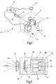
- FIG. 1 an embodiment of the new device is designated in its entirety by the reference numeral 10.
- the device 10 serves here for securing a danger zone 12, which results from the automated movements (indicated by the arrows) of a robot 14. As soon as a person (not shown here) enters the danger area 12, the robot 14 has to be brought into a safe resting position. This is done with the aid of the new device 10.
- the device 10 includes an image acquisition unit 16 and an evaluation and control unit 18.
- the reference numeral 20 denotes a light source which is actuated by the evaluation and control unit 18 in order to illuminate the robot 14 or its danger area 12.
- the light source 20 may also be omitted if the basic brightness in the region of the robot 14 is sufficient to perform an image evaluation with the required recognition reliability.
- Reference numeral 21 designates two contrast patterns arranged in the danger area 12 as reference objects for the image analysis described below.
- the reference objects 21 could also be arranged outside the danger area 12, as long as they are in the viewing angle of the image recording unit 16.
- the reference objects 21 have a defined image contrast, by means of which contamination on the optical entrance window of the image acquisition unit 16 can be detected in the manner described below.
- the image recording unit 16 is driven by the evaluation and control unit 18, which includes, among other functional tests.
- the evaluation and control unit checks 18 the functionality of the image pickup unit 16 based on the in DE 100 17 333 A1 described method.
- any other method of ensuring operational safety may be used, with the apparatus 10 as a whole preferably being designed to meet the requirements of Category 4 of European Standard EN 954-1 or comparable safety requirements.
- the evaluation and control unit 18 recognizes from the obtained image data that a person has entered the danger zone 12, it switches the robot 14 into the safe rest position. It is therefore connected to an operating control of the robot 14, not shown here, or integrated into this.
- the image pickup unit 16 has an objective 22 and an image sensor 24 having a plurality of pixels 26.
- the image sensor 24 is a two-dimensional digital image sensor in CMOS technology or CCD technology.
- the pixels 26 are often referred to as pixels in such image sensors.
- the said image sensors convert incident light into electrical signals and as a rule contain an A / D converter, not shown here, so that the image data are available in digital form for evaluation.
- the present invention can also be used in other image sensors and ultimately even in cameras that work with conventional films.
- the objective 22 includes imaging optics by which an image 28 of the danger area 12 is projected onto the image sensor 24.
- imaging optics by which an image 28 of the danger area 12 is projected onto the image sensor 24.
- a preferred construction of the imaging optics is described below Fig. 4 described.
- Reference numeral 30 denotes a microcontroller or microprocessor together with associated peripherals.
- the processor 30 performs general control functions and may also include the functionality of the evaluation and control unit 18. Conversely, the processor 30 with the functionality described below could also be integrated in the evaluation and control unit 18, which is separate from the image recording unit 16.
- the processor 30 includes three monitoring modules 32, 34, 36 implemented as software and / or hardware (eg, FPGA).
- the monitoring module 32 performs an image brightness monitoring, ie it monitors whether an image brightness value of the current image 28 falls below a predetermined image brightness threshold.
- the image brightness threshold is in Fig. 2 indicated at reference numeral 38 and stored as a parameter in a suitable memory of the device 10.
- the monitoring of the image brightness can be based on the average brightness of the image 28 and / or on the basis of other criteria, for example the maximum number of pixels that are darker than a certain threshold allow and / or the maximum size of contiguous image areas that may be darker than a threshold.
- the monitoring module 34 monitors the image contrast in the image 28.
- An image contrast threshold used as a comparison criterion is indicated at the reference numeral 40 and likewise stored in a suitable memory of the device 10.
- the contrast monitoring preferably takes place on the basis of the two reference objects 21, which cause a defined image contrast in the image 28.
- the monitoring module 36 monitors the (known) position of the reference objects 21 in the current image 28.
- the known position is indicated at the reference numeral 42 and also stored in a suitable memory of the device 10. With the aid of position monitoring, water droplets and other transparent contaminants can be detected on a front object-side glass surface 44 of the image recording unit 16.
- Fig. 3 shows the lens arrangement of a typical wide-angle lens 50 with an aperture 51 and the course of some typical light bundles on the way to the image sensor 24.
- the entrance pupil is in this lens approximately centrally between the front glass surface 44 and the aperture 51 and is indicated at reference numeral 53.
- a first light beam 52 strikes the front, object-side glass surface 44 of the objective 50 from the front and parallel to the optical axis 54.
- the individual beams of the light beam 52 have a somewhat different course within the objective 50, they largely coincide to one or a few pixels of the image sensor 24. All the rays of the light beam 52 hit the image sensor 24 in the extension of the optical axis 54th
- a second exemplified light beam 56 enters slightly obliquely from below into the wide-angle lens 50.
- the individual beams of the light beam 56 in turn undergo different paths, but they reach the image sensor 24 largely congruent, namely at the point 58.
- the individual beams of the light beam 60 reach the image sensor 24 at point 64.
- the pixel 64 is shaded. However, the pixels in the areas 54, 58 remain largely unaffected. As a result, the image sensor 24 in the region of the pixel 64 is "blind", which can lead to a person or an object being able to enter the danger zone 12 unrecognized. The detection reliability is thus dependent on the location of the lens 50 by the contamination 66.
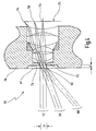
- Fig. 4 shows an embodiment of a preferred lens 70 for the device 10.
- the lens 70 is characterized in that its entrance pupil 72 is located in the region of the front object-side glass surface 44.
- the entrance pupil coincides here with the real aperture diaphragm of the objective 70, which is achieved in that the aperture diaphragm 72 lies closely behind a front glass body 74, which has no significant imaging properties with respect to the transmitted light rays.
- the aperture diaphragm could also lie further inside the objective 70 if the glass body 74 or other glass bodies (not shown here) are designed as suitable lenses in order to project the entrance pupil into the area of the front glass surface 44.
- the entrance pupil 72 has an opening diameter 2r and is here offset at a distance d from the front glass surface 44 into the interior of the objective 70. This makes it possible to realize a flat outer surface of the glass body 74, which lies in a plane with the flat outer surface of a socket 76.
- the position of the entrance pupil shown has the result that the light bundles 52, 56, 60 do not overlap "deeply" in the interior of the objective 70, but already in the area of the front object-side glass surface 44.
- a stain 66 in the area of the front glass surface 44 therefore shadows almost all the pixels 54, 58, 64.
- light rays which pass through a surface spot corresponding to the stain spot 66 on the front glass surface 44 impinge on the image sensor 24 at various points 54, 58, 64.
- the stain 66 therefore, the detection reliability is ensured unless the basic brightness of the light source 66 recorded image is generally insufficient for reliable image analysis. However, due to the brightness monitoring in module 32, this is detected in good time. In the case of the new device 10, the detection reliability is thus not location-dependent, even in the case of singular soiling of the glass surface 44.
- front glass surface 44 may also be realized by plastic lenses or other suitable materials, so that the term “glass” here should not be understood as limiting with respect to a particular material.
Claims (6)
- Dispositif de surveillance d'une région spatiale, notamment pour sécuriser une zone dangereuse (12) d'une installation fonctionnant de manière automatisée (14), comportant une unité d'acquisition d'image (16) destinée à acquérir une image (28) de la région spatiale et comportant une unité d'évaluation et de commande (18) qui déclenche une fonction de sécurité en fonction de l'image (28), dans lequel l'unité d'acquisition d'image (16) possède une optique de formation d'image (22) munie d'un objectif (70) et d'un capteur d'image (24) ayant une pluralité de pixels (26), dans lequel l'unité d'évaluation et de commande (18) comporte un dispositif de surveillance de luminosité d'image (32) qui déclenche la fonction de sécurité lorsque la valeur de luminosité d'image de l'image (28) s'abaisse en dessous d'un seuil de luminosité d'image (38), dans lequel l'unité d'évaluation et de commande (18) comporte un dispositif de surveillance de contraste d'image (34) qui déclenche une fonction de sécurité lorsqu'une valeur de contraste d'image (28) s'abaisse en dessous d'un seuil de contraste d'image (40), et dans lequel l'unité d'évaluation et de commande (18) comporte en outre un dispositif surveillance de position (36) qui déclenche une fonction de sécurité lorsque la position d'un objet de référence détecté (21) dans l'image se modifie, caractérisé en ce que l'optique de formation d'image (22) possède une surface de verre avant (44) côté objet et une pupille d'entrée (72), qui se situe sur ou dans la région de la surface de verre avant (44) côté objet de manière à ce qu'une salissure unique (66) de la surface de verre avant (44) occulte de façon sensiblement homogène la pluralité de pixels (26), et caractérisé par au moins un objet de référence (21) disposé dans la région spatiale, doté d'une valeur de contraste d'image définie que l'unité d'évaluation et de commande (18) surveille afin de détecter une très petite particule de salissure sur la surface de verre avant (44) et ayant une position connue que surveille l'unité d'évaluation et de commande (18) afin de détecter des gouttelettes d'eau et d'autres salissures transparentes sur la surface de verre avant (44).
- Dispositif selon la revendication 1, caractérisé en ce que la pupille d'entrée (72) est située de manière éloignée de la surface de verre avant (44) côté objet à l'intérieur de l'objectif (70), en étant décalée d'une distance (d) qui est inférieure à un rayon d'ouverture (r) de la pupille d'entrée (72).
- Dispositif selon la revendication 1 ou 2, caractérisé en ce que l'optique de formation d'image (22 ; 70) comporte un diaphragme d'ouverture qui se situe dans la région de la surface de verre avant (44) côté objet.
- Dispositif selon la revendication 3, caractérisé en ce que le diaphragme d'ouverture coïncide avec la pupille d'entrée (72).
- Dispositif selon l'une quelconque des revendications 1 à 4, caractérisé en ce que l'optique de formation d'image (20 ; 70) comporte une monture (74) pour la surface de verre avant (44) côté objet qui se termine dans le même plan que la surface de verre avant (44) côté objet.
- Dispositif selon l'une quelconque des revendications 1 à 5, caractérisé en ce que le capteur d'image (24) contient un réseau bidimensionnel de pixels (26), qui est conçu pour acquérir la totalité de l'image (28).
Applications Claiming Priority (2)
| Application Number | Priority Date | Filing Date | Title |
|---|---|---|---|
| DE102004020998A DE102004020998A1 (de) | 2004-04-19 | 2004-04-19 | Vorrichtung zum Überwachen eines Raumbereichs, insbesondere zum Absichern eines Gefahrenbereichs einer automatisiert arbeitenden Anlage |
| PCT/EP2005/003074 WO2005101812A1 (fr) | 2004-04-19 | 2005-03-23 | Dispositif pour surveiller une zone, notamment pour securiser une zone dangereuse d'une installation automatique |
Publications (2)
| Publication Number | Publication Date |
|---|---|
| EP1738580A1 EP1738580A1 (fr) | 2007-01-03 |
| EP1738580B1 true EP1738580B1 (fr) | 2016-08-10 |
Family
ID=34964124
Family Applications (1)
| Application Number | Title | Priority Date | Filing Date |
|---|---|---|---|
| EP05731050.0A Active EP1738580B1 (fr) | 2004-04-19 | 2005-03-23 | Dispositif pour surveiller une zone, notamment pour securiser une zone dangereuse d'une installation automatique |
Country Status (3)
| Country | Link |
|---|---|
| EP (1) | EP1738580B1 (fr) |
| DE (1) | DE102004020998A1 (fr) |
| WO (1) | WO2005101812A1 (fr) |
Families Citing this family (11)
| Publication number | Priority date | Publication date | Assignee | Title |
|---|---|---|---|---|
| DE102005063217C5 (de) * | 2005-12-22 | 2022-08-18 | Pilz Gmbh & Co. Kg | Verfahren zum Konfigurieren einer Überwachungseinrichtung zum Überwachen eines Raumbereichsund entsprechende Überwachungseinrichtung |
| DE102006050235B4 (de) | 2006-10-17 | 2014-02-13 | Pilz Gmbh & Co. Kg | Kamerasystem zum Überwachen eines Raumbereichs |
| DE102006057605A1 (de) * | 2006-11-24 | 2008-06-05 | Pilz Gmbh & Co. Kg | Verfahren und Vorrichtung zum Überwachen eines dreidimensionalen Raumbereichs |
| DE102007004724A1 (de) | 2007-01-22 | 2008-07-24 | Pilz Gmbh & Co. Kg | Kameraeinheit zum Überwachen eines Raumbereichs, insbesondere als Teil einer mitlaufenden Schutzeinrichtung an einem bewegten Maschinenteil |
| DE102007013299A1 (de) * | 2007-03-06 | 2008-09-11 | Cedes Ag | Sensorvorrichtung sowie Anlage mit einem Förderer und einer Sensorvorrichtung |
| EP1988389B1 (fr) * | 2007-05-04 | 2011-07-20 | Sick Ag | Surveillance d'une zone avec la détermination de la contamination d'une surface transparente basée sur le contraste d'image |
| US9067132B1 (en) | 2009-07-15 | 2015-06-30 | Archetype Technologies, Inc. | Systems and methods for indirect control of processor enabled devices |
| US8239047B1 (en) * | 2009-07-15 | 2012-08-07 | Bryan Bergeron | Systems and methods for indirect control of processor enabled devices |
| DE102013019138A1 (de) * | 2013-11-12 | 2015-05-13 | Application Solutions (Electronics and Vision) Ltd. | Verfahren zum Erkennen eines verdeckten Zustands einer Kamera, Kamerasystem und Kraftfahrzeug |
| US10834065B1 (en) | 2015-03-31 | 2020-11-10 | F5 Networks, Inc. | Methods for SSL protected NTLM re-authentication and devices thereof |
| US10404698B1 (en) | 2016-01-15 | 2019-09-03 | F5 Networks, Inc. | Methods for adaptive organization of web application access points in webtops and devices thereof |
Family Cites Families (12)
| Publication number | Priority date | Publication date | Assignee | Title |
|---|---|---|---|---|
| US6631842B1 (en) * | 2000-06-07 | 2003-10-14 | Metrologic Instruments, Inc. | Method of and system for producing images of objects using planar laser illumination beams and image detection arrays |
| JP3511392B2 (ja) | 1993-12-15 | 2004-03-29 | 富士写真光機株式会社 | 3枚玉による結像レンズ |
| US6501536B1 (en) * | 1995-01-18 | 2002-12-31 | Ronald J. Fredricks | Method and apparatus for determining the location of an occupant of a vehicle |
| ATE221232T1 (de) * | 1997-09-15 | 2002-08-15 | Rms Kleine Gmbh Vertrieb Elekt | Verfahren und vorrichtung zur optischen überwachung eines raumbereichs |
| JP2000089122A (ja) | 1998-09-14 | 2000-03-31 | Canon Inc | ドアカメラ |
| DE19938639B4 (de) | 1999-08-14 | 2006-08-24 | Pilz Gmbh & Co. Kg | Vorrichtung zur Absicherung eines Gefahrenbereichs, insbesondere des Gefahrenbereichs einer automatisiert arbeitenden Maschine |
| JP2001066508A (ja) | 1999-08-27 | 2001-03-16 | Canon Inc | 光学機器 |
| JP2001257944A (ja) | 2000-03-10 | 2001-09-21 | Olympus Optical Co Ltd | 小型撮像モジュール |
| DE10017333C2 (de) * | 2000-04-07 | 2003-02-13 | Pilz Gmbh & Co | Schutzvorrichtung zum Absichern eines Gefahrenbereichs sowie Verfahren zum Überprüfen der Funktionssicherheit einer solchen |
| DE10033608A1 (de) * | 2000-07-11 | 2002-02-07 | Pilz Gmbh & Co | Verfahren und Vorrichtung zum Absichern eines Gefahrenbereichs, insbesondere des Gefahrenbereichs einer automatisiert arbeitenden Maschine |
| AU2002311571A1 (en) * | 2001-04-11 | 2002-12-16 | Cynovad, Inc. | Methods and systems for management of information related to the appearance of an object |
| DE10138960A1 (de) * | 2001-08-03 | 2003-02-27 | Pilz Gmbh & Co | Verfahren und Vorrichtung zum Beobachten, Vermessen oder Überwachen eines Raumbereichs |
-
2004
- 2004-04-19 DE DE102004020998A patent/DE102004020998A1/de not_active Withdrawn
-
2005
- 2005-03-23 EP EP05731050.0A patent/EP1738580B1/fr active Active
- 2005-03-23 WO PCT/EP2005/003074 patent/WO2005101812A1/fr active Application Filing
Also Published As
| Publication number | Publication date |
|---|---|
| EP1738580A1 (fr) | 2007-01-03 |
| WO2005101812A1 (fr) | 2005-10-27 |
| DE102004020998A1 (de) | 2005-11-03 |
Similar Documents
| Publication | Publication Date | Title |
|---|---|---|
| EP1738580B1 (fr) | Dispositif pour surveiller une zone, notamment pour securiser une zone dangereuse d'une installation automatique | |
| EP0902402B1 (fr) | Procédé et appareil pour la surveillance optique d'un espace | |
| EP1027235B1 (fr) | Dispositif et procede pour la detection d'objets se trouvant sur un pare-brise | |
| DE102007003023B4 (de) | Optoelektronischer Sensor und Verfahren zum Lichtdurchlässigkeitstest der Schutzscheibe durch Totalreflexion | |
| EP1813961A2 (fr) | Dispositif destiné à la surveillance optoélectronique d'objets | |
| DE102014209197A1 (de) | Vorrichtung und Verfahren zum Erkennen von Niederschlag für ein Kraftfahrzeug | |
| DE102018003762A1 (de) | Überwachungsvorrichtung zum Überwachen eines durch Aufteilen eines Überwachungsbereichs festgelegten räumlichen Bereichs | |
| DE3926349A1 (de) | Optische fehlerinspektionsvorrichtung | |
| DE102004047022A1 (de) | Vorrichtung zur Überwachung von Raumbereichen | |
| DE19704793A1 (de) | Optische Sende- und Empfangseinrichtung | |
| WO2005104527A2 (fr) | Dispositif et procede d'enregistrement d'une image | |
| DE102004020704A1 (de) | Sensorvorrichtung zur Erfassung von Strahlung aus dem Bereich einer Wechselwirkungszone zwischen einem Laserstrahl und einem Werkstück sowie Vorrichtung zur Überwachung eines Laserbearbeitungsvorgangs und Laserbearbeitungskopf | |
| DE10033608A1 (de) | Verfahren und Vorrichtung zum Absichern eines Gefahrenbereichs, insbesondere des Gefahrenbereichs einer automatisiert arbeitenden Maschine | |
| EP1061489A1 (fr) | Détecteur d'intrusion avec dispositif de surveillance contre un sabotage | |
| DE10055689B4 (de) | Verfahren zum Betrieb eines optischen Triangulationslichtgitters | |
| EP0875873B1 (fr) | Capteur opto-électronique | |
| CH651941A5 (de) | Optische anordnung fuer einen strahlungsdetektor. | |
| EP1857838B1 (fr) | Dispositif de protection optoélectrique | |
| EP1983334A1 (fr) | Procédé et dispositif pour la détection optique des contaminants | |
| DE3231025C2 (de) | Einrichtung zur Identifizierung von gepulster Laserstrahlung | |
| EP3822198B1 (fr) | Agencement de détection de marchandises de détail | |
| DE102014116852A1 (de) | Optoelektronischer Sensor mit einem Empfangselement | |
| EP1903352B1 (fr) | Capteur optoélectronique et procédé d'opération d'un capteur optoélectronique | |
| DE202006020659U1 (de) | Optoelektronische Schutzeinrichtung | |
| DE112021003470T5 (de) | System und Verfahren zur Erkennung der Anwesenheit von Fenstern und Spiegeln |
Legal Events
| Date | Code | Title | Description |
|---|---|---|---|
| PUAI | Public reference made under article 153(3) epc to a published international application that has entered the european phase |
Free format text: ORIGINAL CODE: 0009012 |
|
| 17P | Request for examination filed |
Effective date: 20061024 |
|
| AK | Designated contracting states |
Kind code of ref document: A1 Designated state(s): AT BE BG CH CY CZ DE DK EE ES FI FR GB GR HU IE IS IT LI LT LU MC NL PL PT RO SE SI SK TR |
|
| DAX | Request for extension of the european patent (deleted) | ||
| REG | Reference to a national code |
Ref country code: HK Ref legal event code: DE Ref document number: 1099162 Country of ref document: HK |
|
| 17Q | First examination report despatched |
Effective date: 20120224 |
|
| GRAP | Despatch of communication of intention to grant a patent |
Free format text: ORIGINAL CODE: EPIDOSNIGR1 |
|
| RIC1 | Information provided on ipc code assigned before grant |
Ipc: H04N 5/225 20060101AFI20160219BHEP Ipc: G02B 13/00 20060101ALI20160219BHEP Ipc: G02B 13/04 20060101ALI20160219BHEP Ipc: G03B 17/18 20060101ALI20160219BHEP |
|
| INTG | Intention to grant announced |
Effective date: 20160307 |
|
| GRAS | Grant fee paid |
Free format text: ORIGINAL CODE: EPIDOSNIGR3 |
|
| GRAA | (expected) grant |
Free format text: ORIGINAL CODE: 0009210 |
|
| AK | Designated contracting states |
Kind code of ref document: B1 Designated state(s): AT BE BG CH CY CZ DE DK EE ES FI FR GB GR HU IE IS IT LI LT LU MC NL PL PT RO SE SI SK TR |
|
| REG | Reference to a national code |
Ref country code: GB Ref legal event code: FG4D Free format text: NOT ENGLISH |
|
| REG | Reference to a national code |
Ref country code: CH Ref legal event code: EP Ref country code: AT Ref legal event code: REF Ref document number: 819974 Country of ref document: AT Kind code of ref document: T Effective date: 20160815 |
|
| REG | Reference to a national code |
Ref country code: IE Ref legal event code: FG4D Free format text: LANGUAGE OF EP DOCUMENT: GERMAN |
|
| REG | Reference to a national code |
Ref country code: DE Ref legal event code: R096 Ref document number: 502005015318 Country of ref document: DE Ref country code: CH Ref legal event code: NV Representative=s name: RENTSCH PARTNER AG, CH |
|
| REG | Reference to a national code |
Ref country code: LT Ref legal event code: MG4D |
|
| REG | Reference to a national code |
Ref country code: NL Ref legal event code: MP Effective date: 20160810 |
|
| PG25 | Lapsed in a contracting state [announced via postgrant information from national office to epo] |
Ref country code: IS Free format text: LAPSE BECAUSE OF FAILURE TO SUBMIT A TRANSLATION OF THE DESCRIPTION OR TO PAY THE FEE WITHIN THE PRESCRIBED TIME-LIMIT Effective date: 20161210 Ref country code: NL Free format text: LAPSE BECAUSE OF FAILURE TO SUBMIT A TRANSLATION OF THE DESCRIPTION OR TO PAY THE FEE WITHIN THE PRESCRIBED TIME-LIMIT Effective date: 20160810 Ref country code: LT Free format text: LAPSE BECAUSE OF FAILURE TO SUBMIT A TRANSLATION OF THE DESCRIPTION OR TO PAY THE FEE WITHIN THE PRESCRIBED TIME-LIMIT Effective date: 20160810 Ref country code: FI Free format text: LAPSE BECAUSE OF FAILURE TO SUBMIT A TRANSLATION OF THE DESCRIPTION OR TO PAY THE FEE WITHIN THE PRESCRIBED TIME-LIMIT Effective date: 20160810 |
|
| PG25 | Lapsed in a contracting state [announced via postgrant information from national office to epo] |
Ref country code: SE Free format text: LAPSE BECAUSE OF FAILURE TO SUBMIT A TRANSLATION OF THE DESCRIPTION OR TO PAY THE FEE WITHIN THE PRESCRIBED TIME-LIMIT Effective date: 20160810 Ref country code: GR Free format text: LAPSE BECAUSE OF FAILURE TO SUBMIT A TRANSLATION OF THE DESCRIPTION OR TO PAY THE FEE WITHIN THE PRESCRIBED TIME-LIMIT Effective date: 20161111 Ref country code: PT Free format text: LAPSE BECAUSE OF FAILURE TO SUBMIT A TRANSLATION OF THE DESCRIPTION OR TO PAY THE FEE WITHIN THE PRESCRIBED TIME-LIMIT Effective date: 20161212 Ref country code: ES Free format text: LAPSE BECAUSE OF FAILURE TO SUBMIT A TRANSLATION OF THE DESCRIPTION OR TO PAY THE FEE WITHIN THE PRESCRIBED TIME-LIMIT Effective date: 20160810 Ref country code: PL Free format text: LAPSE BECAUSE OF FAILURE TO SUBMIT A TRANSLATION OF THE DESCRIPTION OR TO PAY THE FEE WITHIN THE PRESCRIBED TIME-LIMIT Effective date: 20160810 |
|
| REG | Reference to a national code |
Ref country code: FR Ref legal event code: PLFP Year of fee payment: 13 |
|
| PG25 | Lapsed in a contracting state [announced via postgrant information from national office to epo] |
Ref country code: RO Free format text: LAPSE BECAUSE OF FAILURE TO SUBMIT A TRANSLATION OF THE DESCRIPTION OR TO PAY THE FEE WITHIN THE PRESCRIBED TIME-LIMIT Effective date: 20160810 Ref country code: EE Free format text: LAPSE BECAUSE OF FAILURE TO SUBMIT A TRANSLATION OF THE DESCRIPTION OR TO PAY THE FEE WITHIN THE PRESCRIBED TIME-LIMIT Effective date: 20160810 |
|
| REG | Reference to a national code |
Ref country code: DE Ref legal event code: R097 Ref document number: 502005015318 Country of ref document: DE |
|
| PG25 | Lapsed in a contracting state [announced via postgrant information from national office to epo] |
Ref country code: CZ Free format text: LAPSE BECAUSE OF FAILURE TO SUBMIT A TRANSLATION OF THE DESCRIPTION OR TO PAY THE FEE WITHIN THE PRESCRIBED TIME-LIMIT Effective date: 20160810 Ref country code: SK Free format text: LAPSE BECAUSE OF FAILURE TO SUBMIT A TRANSLATION OF THE DESCRIPTION OR TO PAY THE FEE WITHIN THE PRESCRIBED TIME-LIMIT Effective date: 20160810 Ref country code: BG Free format text: LAPSE BECAUSE OF FAILURE TO SUBMIT A TRANSLATION OF THE DESCRIPTION OR TO PAY THE FEE WITHIN THE PRESCRIBED TIME-LIMIT Effective date: 20161110 Ref country code: DK Free format text: LAPSE BECAUSE OF FAILURE TO SUBMIT A TRANSLATION OF THE DESCRIPTION OR TO PAY THE FEE WITHIN THE PRESCRIBED TIME-LIMIT Effective date: 20160810 |
|
| PLBE | No opposition filed within time limit |
Free format text: ORIGINAL CODE: 0009261 |
|
| STAA | Information on the status of an ep patent application or granted ep patent |
Free format text: STATUS: NO OPPOSITION FILED WITHIN TIME LIMIT |
|
| 26N | No opposition filed |
Effective date: 20170511 |
|
| REG | Reference to a national code |
Ref country code: HK Ref legal event code: GR Ref document number: 1099162 Country of ref document: HK |
|
| PG25 | Lapsed in a contracting state [announced via postgrant information from national office to epo] |
Ref country code: SI Free format text: LAPSE BECAUSE OF FAILURE TO SUBMIT A TRANSLATION OF THE DESCRIPTION OR TO PAY THE FEE WITHIN THE PRESCRIBED TIME-LIMIT Effective date: 20160810 |
|
| REG | Reference to a national code |
Ref country code: CH Ref legal event code: PCAR Free format text: NEW ADDRESS: BELLERIVESTRASSE 203 POSTFACH, 8034 ZUERICH (CH) |
|
| GBPC | Gb: european patent ceased through non-payment of renewal fee |
Effective date: 20170323 |
|
| PG25 | Lapsed in a contracting state [announced via postgrant information from national office to epo] |
Ref country code: MC Free format text: LAPSE BECAUSE OF FAILURE TO SUBMIT A TRANSLATION OF THE DESCRIPTION OR TO PAY THE FEE WITHIN THE PRESCRIBED TIME-LIMIT Effective date: 20160810 |
|
| REG | Reference to a national code |
Ref country code: IE Ref legal event code: MM4A |
|
| PG25 | Lapsed in a contracting state [announced via postgrant information from national office to epo] |
Ref country code: LU Free format text: LAPSE BECAUSE OF NON-PAYMENT OF DUE FEES Effective date: 20170323 |
|
| PG25 | Lapsed in a contracting state [announced via postgrant information from national office to epo] |
Ref country code: IE Free format text: LAPSE BECAUSE OF NON-PAYMENT OF DUE FEES Effective date: 20170323 Ref country code: GB Free format text: LAPSE BECAUSE OF NON-PAYMENT OF DUE FEES Effective date: 20170323 |
|
| REG | Reference to a national code |
Ref country code: BE Ref legal event code: MM Effective date: 20170331 |
|
| REG | Reference to a national code |
Ref country code: FR Ref legal event code: PLFP Year of fee payment: 14 |
|
| PG25 | Lapsed in a contracting state [announced via postgrant information from national office to epo] |
Ref country code: BE Free format text: LAPSE BECAUSE OF NON-PAYMENT OF DUE FEES Effective date: 20170331 |
|
| PG25 | Lapsed in a contracting state [announced via postgrant information from national office to epo] |
Ref country code: HU Free format text: LAPSE BECAUSE OF FAILURE TO SUBMIT A TRANSLATION OF THE DESCRIPTION OR TO PAY THE FEE WITHIN THE PRESCRIBED TIME-LIMIT; INVALID AB INITIO Effective date: 20050323 |
|
| PG25 | Lapsed in a contracting state [announced via postgrant information from national office to epo] |
Ref country code: CY Free format text: LAPSE BECAUSE OF NON-PAYMENT OF DUE FEES Effective date: 20160810 |
|
| PG25 | Lapsed in a contracting state [announced via postgrant information from national office to epo] |
Ref country code: TR Free format text: LAPSE BECAUSE OF FAILURE TO SUBMIT A TRANSLATION OF THE DESCRIPTION OR TO PAY THE FEE WITHIN THE PRESCRIBED TIME-LIMIT Effective date: 20160810 |
|
| PGFP | Annual fee paid to national office [announced via postgrant information from national office to epo] |
Ref country code: AT Payment date: 20200320 Year of fee payment: 16 |
|
| PGFP | Annual fee paid to national office [announced via postgrant information from national office to epo] |
Ref country code: CH Payment date: 20200319 Year of fee payment: 16 |
|
| PGFP | Annual fee paid to national office [announced via postgrant information from national office to epo] |
Ref country code: IT Payment date: 20210329 Year of fee payment: 17 Ref country code: FR Payment date: 20210323 Year of fee payment: 17 |
|
| REG | Reference to a national code |
Ref country code: CH Ref legal event code: PL |
|
| REG | Reference to a national code |
Ref country code: AT Ref legal event code: MM01 Ref document number: 819974 Country of ref document: AT Kind code of ref document: T Effective date: 20210323 |
|
| PG25 | Lapsed in a contracting state [announced via postgrant information from national office to epo] |
Ref country code: AT Free format text: LAPSE BECAUSE OF NON-PAYMENT OF DUE FEES Effective date: 20210323 Ref country code: CH Free format text: LAPSE BECAUSE OF NON-PAYMENT OF DUE FEES Effective date: 20210331 Ref country code: LI Free format text: LAPSE BECAUSE OF NON-PAYMENT OF DUE FEES Effective date: 20210331 |
|
| REG | Reference to a national code |
Ref country code: DE Ref legal event code: R079 Ref document number: 502005015318 Country of ref document: DE Free format text: PREVIOUS MAIN CLASS: H04N0005225000 Ipc: H04N0023000000 |
|
| PG25 | Lapsed in a contracting state [announced via postgrant information from national office to epo] |
Ref country code: FR Free format text: LAPSE BECAUSE OF NON-PAYMENT OF DUE FEES Effective date: 20220331 |
|
| PG25 | Lapsed in a contracting state [announced via postgrant information from national office to epo] |
Ref country code: IT Free format text: LAPSE BECAUSE OF NON-PAYMENT OF DUE FEES Effective date: 20220323 |
|
| PGFP | Annual fee paid to national office [announced via postgrant information from national office to epo] |
Ref country code: DE Payment date: 20230425 Year of fee payment: 19 |