EP0902402B1 - Procédé et appareil pour la surveillance optique d'un espace - Google Patents
Procédé et appareil pour la surveillance optique d'un espace Download PDFInfo
- Publication number
- EP0902402B1 EP0902402B1 EP98117081A EP98117081A EP0902402B1 EP 0902402 B1 EP0902402 B1 EP 0902402B1 EP 98117081 A EP98117081 A EP 98117081A EP 98117081 A EP98117081 A EP 98117081A EP 0902402 B1 EP0902402 B1 EP 0902402B1
- Authority
- EP
- European Patent Office
- Prior art keywords
- evaluation unit
- camera
- elevator
- area
- monitoring system
- Prior art date
- Legal status (The legal status is an assumption and is not a legal conclusion. Google has not performed a legal analysis and makes no representation as to the accuracy of the status listed.)
- Expired - Lifetime
Links
Images


Classifications
-
- G—PHYSICS
- G08—SIGNALLING
- G08B—SIGNALLING SYSTEMS, e.g. PERSONAL CALLING SYSTEMS; ORDER TELEGRAPHS; ALARM SYSTEMS
- G08B13/00—Burglar, theft or intruder alarms
- G08B13/18—Actuation by interference with heat, light, or radiation of shorter wavelength; Actuation by intruding sources of heat, light, or radiation of shorter wavelength
- G08B13/189—Actuation by interference with heat, light, or radiation of shorter wavelength; Actuation by intruding sources of heat, light, or radiation of shorter wavelength using passive radiation detection systems
- G08B13/194—Actuation by interference with heat, light, or radiation of shorter wavelength; Actuation by intruding sources of heat, light, or radiation of shorter wavelength using passive radiation detection systems using image scanning and comparing systems
- G08B13/196—Actuation by interference with heat, light, or radiation of shorter wavelength; Actuation by intruding sources of heat, light, or radiation of shorter wavelength using passive radiation detection systems using image scanning and comparing systems using television cameras
- G08B13/19602—Image analysis to detect motion of the intruder, e.g. by frame subtraction
- G08B13/19604—Image analysis to detect motion of the intruder, e.g. by frame subtraction involving reference image or background adaptation with time to compensate for changing conditions, e.g. reference image update on detection of light level change
-
- G—PHYSICS
- G08—SIGNALLING
- G08B—SIGNALLING SYSTEMS, e.g. PERSONAL CALLING SYSTEMS; ORDER TELEGRAPHS; ALARM SYSTEMS
- G08B13/00—Burglar, theft or intruder alarms
- G08B13/18—Actuation by interference with heat, light, or radiation of shorter wavelength; Actuation by intruding sources of heat, light, or radiation of shorter wavelength
- G08B13/189—Actuation by interference with heat, light, or radiation of shorter wavelength; Actuation by intruding sources of heat, light, or radiation of shorter wavelength using passive radiation detection systems
- G08B13/194—Actuation by interference with heat, light, or radiation of shorter wavelength; Actuation by intruding sources of heat, light, or radiation of shorter wavelength using passive radiation detection systems using image scanning and comparing systems
- G08B13/196—Actuation by interference with heat, light, or radiation of shorter wavelength; Actuation by intruding sources of heat, light, or radiation of shorter wavelength using passive radiation detection systems using image scanning and comparing systems using television cameras
- G08B13/19639—Details of the system layout
- G08B13/19641—Multiple cameras having overlapping views on a single scene
Definitions
- the invention relates on the one hand to a method for the optical monitoring of a Room area, in particular the door area of an elevator, with the space area a digital image is generated with a camera and the gray values of the current one Image with the gray values of a reference image in an evaluation unit compared pixel by pixel and the result is evaluated.
- an optical monitoring system for detecting a spatial area, in particular the door area of an elevator, with at least one digital camera and an evaluation unit, the digital camera having a camera module and one A / D converter and the evaluation unit a microprocessor and an image memory and the evaluation unit shows the gray values of a current image with the Gray values of a reference image are compared pixel by pixel and the difference between evaluates the gray values of the current image and the gray values of the reference image.
- Light barriers are used, being on one opening side of the elevator the transmitters and the receivers are arranged on the other opening side.
- the light barriers should ensure the presence a person or an object in the monitored area detect that the light beam between transmitter and receiver through the Person or object is interrupted.
- the first problem can be increased by increasing the number of the light barriers are reduced, but this automatically increases the Adjustment of the now more numerous transmitters and receivers.
- the number of transmitters and receivers is increased to include smaller items
- To the danger of such misinformation Prevent complex controls for the transmitter and the Recipients necessary to ensure that a recipient is only ready to receive when the transmitter assigned to it has emitted a light beam.
- Such a monitoring system is from the German published application 195 25 875 known. It is used to monitor a safety-relevant area in front of an automatic door or a passage gate with an access control system used.
- the German published application 195 25 875 known surveillance system is the presence of people in the relevant area is detected, so that the area close to the ground is used as the monitoring field is recorded by a CCD camera. Because such optical surveillance systems With a digital camera they are usually expensive only used where there is a high security requirement.
- the object of the present invention is now a method for optical monitoring a room area or an optical monitoring system with which, on the one hand, a reliable detection of even very small objects is possible in the room area, which is extremely reliable and fail-safe is working.
- the evaluation unit the functionality of the camera monitors, in particular the presence of a synchronous signal from the camera and / or falling below and / or exceeding a basic brightness of the current image and / or the undershoot of a predetermined brightness scatter is checked.
- the evaluation unit which has a microprocessor, does not only have the Task, the actual evaluation and processing of those supplied by the camera Carry out information, but at the same time it also checks the functionality the camera. Monitoring can take place both during the active Operation of the camera as well as during downtimes of the camera or the elevator. A failure of the camera can be easily done by cyclically testing one Synchronous signal can be determined.
- the security of the optical monitoring can thereby advantageously further be increased that a monitoring processor to check the evaluation unit cyclically sends test signals to the evaluation unit and vice versa the evaluation unit to check the monitoring processor also test signals to the Monitoring processor sends.
- the monitoring processor sends a test signal to the evaluation unit, it must send the test signal within a defined period of time Acknowledge. If the monitoring processor does not receive this acknowledgment, it means this means that the evaluation unit has an error. Works accordingly also control of the monitoring processor from the evaluation unit.
- the method according to the invention is further improved by that the monitoring processor periodically at the instruction of the evaluation unit Sends test images to an input, in particular to a video multiplex input the camera.
- the transmission of the test image from the monitoring processor at an input of the camera is acknowledged by the evaluation unit, so that this checked the processing of the test image in the digital camera.
- This Monitoring process is thus a dynamic process; the process remains stationary, so an error is recognizable.
- the area to be monitored is preferably provided by an illumination device illuminated.
- This lighting device ensures that there is always sufficient light available for taking the pictures, so that the Monitoring regardless of the very different lighting conditions in use can take place.
- the lighting device works with light from the visible wavelength range, this is the monitored area for the user recognizable.
- the light can then be focused using rod lenses and as a wide line be configured on the floor of the monitoring area.
- the lighting device works on the other hand, with light from the infrared range, can be prevented be that misinformation is created by scattered light from the environment.
- the lighting device works in pulsed mode, thereby a much higher light output is possible than in continuous operation.
- the evaluation unit periodically switches a light emitting diode which blinds the camera.
- the evaluation unit then makes a comparison the image pattern recorded by the camera with one in an image memory stored preset image pattern. This can be done with a single Test the entire digital camera for errors, d. H. both the actual Camera optics that perform the image adjustment with the camera module Camera electronics and the A / D converter.
- the image memory is also checks which of the evaluation units is included. Even if only in one If these components fail, this is determined by this test procedure.
- the output signal of the evaluation unit within the control of the elevator logically subordinate to a fire alarm. This ensures that in the event of a fire, the elevator definitely goes to the next floor, regardless from the signal of the evaluation unit.
- the fire alarm can, for example come from a smoke detector inside the elevator or triggered externally have been.
- the "alarm" signal of the evaluation unit be logical to all others Superordinate control commands of the elevator, this could lead to that at In the event of a fire, the elevator would stop automatically, even if it did would be located between two floors. This would be especially the case with passenger lifts, but also with freight lifts, too great a risk.
- the microprocessor is functional monitors the digital camera, especially the presence a synchronous signal from the camera and / or falling below and / or exceeding the Basic brightness of the current image and / or falling below a predetermined Brightness scatter checked.
- the monitoring system is a service interface for connecting a parameterization device, for example a computer and on the other hand is connected to the control of the elevator.
- a parameterization device for example a computer
- the optical surveillance system on site optimally match the given requirements and conditions of use. So exactly the image section that is to be monitored, for example what is selected happens by setting the correct opening angle of the camera.
- the threshold value from which the difference between the pixel of the current image and the pixel of the reference image as a change recognized and thus counted as errors.
- the number of allowed Errors are set from which the monitoring system generates an "alarm" signal.
- An illuminating device emitting infrared light is preferably provided and the cameras are equipped with an infrared bandpass filter.
- an LED array can be used as a lighting device.
- the infrared bandpass filter is prevented from stray light from the environment Misinformation can arise.
- a reference picture of the area to be monitored is made and temporarily stored in an image memory.
- the current image is then created and also cached.
- the one labeled n in the block diagram Count variable for the pixels is initially set to "0". If both pictures are saved, so n is increased by "1" and thus the first pixel of the reference image and the corresponding first pixels of the current image in the evaluation unit with one another compared. For this purpose, the gray values of the two pixels are subtracted from one another and the absolute amount of the difference is formed. If the absolute amount is greater than one previously entered threshold value, this is considered an error. The number m of Errors which are "0" at the beginning of the comparison are increased by "1".
- the evaluation unit If the error is greater than a previously set limit value X, the evaluation unit generates an "alarm" signal as the output signal. If the number m of errors is smaller than the limit value X, it is compared whether the number n of those examined so far Pixel is equal to the number E of all available pixels. If n is E, i. H. they are all Pixels of the current image and the reference image have been compared with one another, see above the evaluation unit generates an "ok" signal as the output signal. If in the comparison of the two gray values, the absolute amount of the difference is smaller than the threshold value it is checked whether the number n of the examined pixels is equal to the number E of all existing pixels. If this is the case, an "ok" signal is also output here. However, the number n of pixels examined is smaller than the number E of all existing pixels, n is increased by "1" and it becomes the next pixel of the reference image and the current image compared.
- the digital camera 2 shows a block diagram of an optical monitoring system according to the invention with a digital camera 2 and an evaluation unit 3.
- the digital camera 2 initially consists of camera optics 4 which are attached to one - at least two Inputs E 1 and E 2 - camera module 5 is connected, and from a A / D converter 6.
- the input E 2 of the camera module 5 is as a video multiplexer input educated.
- the digital camera 2 has a CCD chip with a size of, for example, 530 x 590 pixels. Different camera modules 5 can be used Camera optics 4 with different opening angles between for example 30 ° and 70 ° can be connected.
- the evaluation unit 3 consists of at least one microprocessor 7, for example a 16 bit MC 68332 microprocessor, and an image memory 8.
- the Image memory 8 receives from A / D converter 6 those recorded by camera 2 Pictures.
- the evaluation unit 3 also includes a number of memories 9 to 11, in which the program data for the monitoring program are stored are memory 9, which on the other hand contains the configuration data, for example monitoring window area, Brightness limit etc. included. This configuration data are stored in the memories 10 and 11, so that an ongoing comparison of the Configuration data is possible.
- the image memory 8 could also be the digital camera 2 instead of the evaluation unit 3 be attributed to what the function of the optical monitoring system as a whole makes no difference.
- the evaluation unit 3 and in particular the monitor Microprocessor 7 the functionality of the digital camera 2, in which the presence a synchronous signal from the camera 2 and / or falling below and / or exceeding a basic brightness of the current image and / or falling below one predetermined brightness spread is checked.
- This will not only be a Total failure of the camera 2 detected, but by monitoring the basic brightness also a lighting failure on the one hand and dazzling of the camera optics 4 detected by extraneous light on the other hand.
- Both the error limit for the basic brightness and for the brightness scatter can be set when the monitoring device is put into operation and if necessary can also be adapted later to changed conditions.
- the optical monitoring system represented by the block diagram in FIG. 2 also includes a monitoring processor 12 which, for example, includes a PIC 16 C 54 microcontroller can be implemented.
- the monitoring processor 12 is on the one hand with the evaluation unit 3 and on the other hand with the Input E 2 of the camera module 5 connected. Through the bidirectional connection between the monitoring processor 12 and the evaluation unit 3 can both the monitoring processor 12 check the evaluation unit 3 and vice versa the evaluation unit 3 transfers the monitoring processor 12.
- the monitoring processor 12 sends a test signal to the evaluation unit 3, which is acknowledged by the evaluation unit 3 within a defined period of time must become.
- the cycle time for such a check is usually less than 200 ms.
- the monitoring processor 12 also the digital camera 2, in particular the A / D converter 6 and the image memory 8, be checked.
- the microprocessor 7 sends a request for this to send a test image to the monitoring processor 12. This requirement the microprocessor 7 is acknowledged by the monitoring processor 12, which thereupon a test pattern to the video multiplexer input E 2 of the camera module 5 sends.
- the microprocessor 7 monitors the digitized by the A / D converter 6 and test image stored in the image memory 8 and evaluates any deviations to a given pattern. Has the conversion and storage of the test pattern works correctly, the microprocessor 7 takes its Monitoring processor 12 sent back request, whereupon the monitoring processor 12 also withdraws its acknowledgment. So this process is dynamic; if the process remains stationary, that is, the microprocessor 7 and / or the monitoring processor 12 its request or its acknowledgment not return, an error message is issued.
- An illumination device 16 is provided as camera lighting, and several Has infrared light emitting diodes 17.
- the LEDs 17 are pulsed at high power during image acquisition.
- Such a lighting device 16 can be especially bad or strongly changing Light conditions can be advantageous.
- the camera 2 can be blinded for test purposes. Becomes the light emitting diode 18 is controlled by the evaluation unit 3, so can by the glare the camera 2 the entire branch of the Surveillance system to be tested. It is the camera optics 4, the Camera module 5, the A / D converter 6 and the image memory 8 and their connection checked with each other.
- the microprocessor 7 records what is recorded by the camera 2 Image compared with a previously saved image.
- Fig. 2 there are two voltage converters 19 and a voltage monitoring device 20 shown.
- the voltage converter 19 is used on the one hand a conversion of the supply voltage from 24 V to 5 V, on the other hand a conversion from 5 V to 9 V as the supply voltage for the camera module 5.
- FIG. 3 schematically shows the door area 1 of an elevator, in which two cameras 2 and two lighting devices 16 embedded in the ceiling 21 of the elevator are.
- the cameras 2 each have a lens with an aperture angle 22 of 70 ° and are arranged in the middle of the ceiling 21.
- the door area 1 has a height of 23 and a width 24 of 2.50 m each.
- the selected area to be monitored 1 covers the entire width 24 of the door area 1, but only a height 25 of 2.00 m.
- the two cameras 2 are aligned so that they cover the entire area grasp it on the floor 26 of the door area 1 in the middle even to a small one Overlap area 27 comes. This makes it possible to monitor errors of cameras 2 by performing a comparison of the overlap area 27, of which both cameras 2 take a current picture becomes. If both cameras 2 are working properly, the respective pixels must be those of the overlap area 27 have been made to match for both cameras 2. If this is not the case, an error message can be sent to a control station be issued.
- FIG. 4 is a schematic diagram of a second embodiment of an optical Monitoring system shown.
- five Cameras 2 used with an opening angle 22 of 70 °. So that becomes a Room area with a width 24 of 5.00 m and a height 25 of 1.73 m completely supervised.
- the cameras 2 are equipped with a CCD sensor with a resolution of 530 x 590 pixels.
- the resolution of the cameras 2, which are at a height of 28 of 2.50 m are attached to the ceiling 21, is 6.6 mm per pixel.
- the distance 29 of the cameras 2 is 1.07 m and is the same between all cameras 2. there there are several overlap areas 27, through which an error monitoring the cameras 2 is possible.
- a point 30 is monitored by three or more cameras 2, so not only a general error detection of the cameras 2 is possible, but it can even be evaluated which camera 2 is faulty. If, for example for point 30, which is monitored by the three central cameras 2, two cameras 2 have stored a matching pixel, the third camera 2 however, if the pixel is different, it is very likely to be third camera 2 defective.
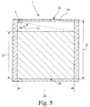
- FIG. 5 shows a schematic diagram of an optical monitoring system with only one Camera 2.
- Camera 2 is located in the upper left corner of door area 1 of the elevator. Due to the large opening angle 22 of the lens of the camera 2 The entire area to be monitored can have a width of about 100 ° 2.50 m and a height 25 of 2.00 m can be detected.
- the door area 1 is not too large, safe monitoring of door area 1 with only one Camera 2 possible, which reduces the cost of the optical surveillance system can be.
Landscapes
- Physics & Mathematics (AREA)
- General Physics & Mathematics (AREA)
- Engineering & Computer Science (AREA)
- Computer Vision & Pattern Recognition (AREA)
- Closed-Circuit Television Systems (AREA)
- Holo Graphy (AREA)
- Indicating And Signalling Devices For Elevators (AREA)
- Burglar Alarm Systems (AREA)
Claims (15)
- Procédé pour le contrôle optique d'une zone d'espace, en particulier de la zone de porte d'un ascenseur, une image numérique de la zone d'espace étant générée avec une caméra numérique et les valeurs de gris de l'image actuelle étant comparées pixel par Pixel avec les valeurs de gris d'une image de référence dans une unité d'analyse et le résultat étant analysé, caractérisé en ce que l'unité d'analyse contrôle le bon fonctionnement de la caméra, contrôle en particulier la présence d'un signal synchrone de la caméra et/ou le sous-dépassement et/ou le dépassement d'une luminosité de base de l'image actuelle et/ou le sous-dépassement d'une diffusion de luminosité prédéfinie.
- Procédé selon la revendication 1, caractérisé en ce qu'un processeur de contrôle envoie de façon cyclique des signaux de test à l'unité d'analyse pour le contrôle de l'unité d'analyse et inversement l'unité d'analyse envoie également des signaux de test au processeur de contrôle pour le contrôle du processeur de contrôle.
- Procédé selon la revendication 2, caractérisé en ce que le processeur de contrôle envoie sur l'ordre de l'unité d'analyse de façon périodique des images de test à une entrée, en particulier à une entrée multiplex vidéo de la caméra.
- Procédé selon l'une quelconque des revendications 1 à 3, caractérisé en ce que la zone d'espace à contrôler est éclairée par un dispositif d'éclairage, en particulier par des diodes électroluminescentes avec une lumière infrarouge exploitée en mode pulsé avec un rendement élevé.
- Procédé selon l'une quelconque des revendications 1 à 4, caractérisé en ce que la caméra est éblouie par une diode électroluminescente à la demande de l'unité d'analyse et l'unité d'analyse compare le modèle d'image enregistré dessus par la caméra avec un modèle d'image prédéfini et mémorisé dans une mémoire d'images.
- Procédé selon l'une quelconque des revendications 1 à 5, caractérisé en ce que, lorsque le montant absolu de la différence de deux valeurs de gris se trouve sur une valeur seuil définie, celle-ci est comptée comme erreur et l'unité d'analyse génère un signal binaire en fonction du nombre des défauts.
- Procédé selon l'une quelconque des revendications 1 à 6, caractérisé en ce qu'une nouvelle image de référence est générée et mémorisée après un certain nombre d'analyses sans incident, de sorte qu'on a une adaptation automatique à des conditions de mesure qui varient.
- Procédé pour le contrôle de la zone de porte d'un ascenseur selon l'une quelconque des revendications 1 à 7, caractérisé en ce qu'une fermeture des porte est empêchée en cas de détection d'un objet dans la zone de porte de l'ascenseur, mais que dans le cas d'un incendie survenant dans l'ascenseur, celui-ci va de toute façon jusqu'à l'étage supérieur, indépendamment du signal de l'unité d'analyse.
- Procédé selon la revendication 8, caractérisé en ce que la commande d'ascenseur contrôle de façon cyclique la communication avec l'unité d'analyse.
- Système de contrôle optique pour la détection d'une zone d'espace, en particulier de la zone de porte (1) d'un ascenseur, avec au moins une caméra (2) numérique et une unité d'analyse (3), la caméra (2) numérique présentant un module de caméra (5) et un convertisseur analogique - numérique (6) et l'unité d'analyse (3) présentant un microprocesseur (7) et une mémoire d'images (8) et l'unité d'analyse (3) comparant pixel par pixel les valeurs de gris d'une image actuelle avec les valeurs de gris d'une image de référence et analysant la différence entre les valeurs de gris de l'image actuelle et les valeurs de gris de l'image de référence, caractérisé en ce que le microprocesseur (7) contrôle le bon fonctionnement de la caméra (2) numérique, en particulier la présence d'un signal synchrone de la caméra (2) et/ou le sous-dépassement et/ou le sur-dépassement d'une luminosité de base de l'image actuelle et/ou le sous-dépassement d'un diffusion de luminosité prédéfinie.
- Système de contrôle optique selon la revendication 10, caractérisé en ce qu'un processeur de contrôle (12) est présent en supplément et le processeur de contrôle (12) contrôle le microprocesseur (7) et/ou contrôle la caméra (2) numérique seul ou en même temps que le microprocesseur (7), an particulier le convertisseur analogique numérique (6) et la mémoire d'images (8).
- Système de contrôle optique selon la revendication 11, caractérisé en ce que le microprocesseur (7) contrôle le processeur de contrôle (12).
- Système de contrôle optique selon l'une quelconque des revendications 10 à 12, caractérisé en ce que le système de contrôle présente d'une part une interface de service (13) pour le branchement d'un système de paramétrage et est raccordé d'autre part à la commande de l'ascenseur.
- Système de contrôle optique selon l'une quelconque des revendications 10 à 13, caractérisé en ce qu'il est prévu un système d'éclairage (16) émettant une lumière infrarouge, qui comprend de préférence un dispositif à diodes électroluminescentes et la caméra (2) est équipée d'un filtre passe-bande à infrarouge.
- Procédé selon l'une quelconque des revendications 1 à 9, avec lequel un système de contrôle optique est utilisé selon l'une quelconque des revendications 10 à 14, caractérisé en ce que plusieurs caméras (2) contrôlent un point (30) et un contrôle des erreurs des caméras (2) s'effectue par comparaison des pixels faits par les différentes caméras (2) du point contrôlé (30).
Applications Claiming Priority (4)
| Application Number | Priority Date | Filing Date | Title |
|---|---|---|---|
| DE19740599 | 1997-09-15 | ||
| DE19740599 | 1997-09-15 | ||
| DE19743874 | 1997-10-04 | ||
| DE19743874 | 1997-10-04 |
Publications (3)
| Publication Number | Publication Date |
|---|---|
| EP0902402A2 EP0902402A2 (fr) | 1999-03-17 |
| EP0902402A3 EP0902402A3 (fr) | 2000-05-17 |
| EP0902402B1 true EP0902402B1 (fr) | 2002-07-24 |
Family
ID=26040008
Family Applications (1)
| Application Number | Title | Priority Date | Filing Date |
|---|---|---|---|
| EP98117081A Expired - Lifetime EP0902402B1 (fr) | 1997-09-15 | 1998-09-09 | Procédé et appareil pour la surveillance optique d'un espace |
Country Status (3)
| Country | Link |
|---|---|
| EP (1) | EP0902402B1 (fr) |
| AT (1) | ATE221232T1 (fr) |
| DE (1) | DE59804862D1 (fr) |
Cited By (3)
| Publication number | Priority date | Publication date | Assignee | Title |
|---|---|---|---|---|
| US7310109B2 (en) | 2000-04-07 | 2007-12-18 | Pilz Gmbh & Co. | Protective device for safeguarding a hazardous area and method of checking the functional reliability of such a device |
| EP3855735A1 (fr) | 2020-01-27 | 2021-07-28 | Sick Ag | Mise en sécurité d'une machine |
| EP3995852A1 (fr) | 2020-11-06 | 2022-05-11 | Sick Ag | Mesurer une distance d'un objet |
Families Citing this family (26)
| Publication number | Priority date | Publication date | Assignee | Title |
|---|---|---|---|---|
| DE29911391U1 (de) * | 1999-06-30 | 1999-10-14 | Sick AG, 79183 Waldkirch | Optoelektronisches Überwachungssystem |
| DE29911390U1 (de) * | 1999-06-30 | 1999-08-12 | Sick AG, 79183 Waldkirch | Optoelektronisches Überwachungssystem |
| DE10017344C1 (de) * | 2000-04-07 | 2001-11-29 | Pilz Gmbh & Co | Verfahren und Vorrichtung zum Überprüfen der Funktionssicherheit einer Bildaufnahmeeinheit |
| DE10017333C2 (de) * | 2000-04-07 | 2003-02-13 | Pilz Gmbh & Co | Schutzvorrichtung zum Absichern eines Gefahrenbereichs sowie Verfahren zum Überprüfen der Funktionssicherheit einer solchen |
| DE10033608A1 (de) * | 2000-07-11 | 2002-02-07 | Pilz Gmbh & Co | Verfahren und Vorrichtung zum Absichern eines Gefahrenbereichs, insbesondere des Gefahrenbereichs einer automatisiert arbeitenden Maschine |
| DE10047896A1 (de) * | 2000-09-26 | 2002-04-11 | Saftey Control | Verfahren zum Überprüfen der Funktionstüchtigkeit einer Sensoreinrichtung |
| FR2829755B1 (fr) * | 2001-09-18 | 2004-01-23 | Autinor | Procede de surveillance d'une cabine d'ascenseur |
| US7154531B2 (en) * | 2001-10-26 | 2006-12-26 | The Chamberlain Group, Inc. | Detecting objects by digital imaging device |
| DE10205691A1 (de) | 2002-02-04 | 2003-08-14 | Pilz Gmbh & Co | Verfahren zum Überprüfen der Funktonssicherheit eines Bildsensors sowie Vorrichtung mit einem Bildsensor |
| DE10224031B3 (de) * | 2002-05-31 | 2004-01-29 | Leuze Lumiflex Gmbh + Co. Kg | Vorrichtung zur Überwachung eines Erfassungsbereiches an einem Arbeitsmittel |
| DE10251584B4 (de) | 2002-11-06 | 2004-11-04 | Leuze Lumiflex Gmbh + Co. Kg | Verfahren und Vorrichtung zur Überwachung eines Erfassungsbereiches |
| AT500925A1 (de) * | 2003-03-05 | 2006-04-15 | Walter Dipl Ing Lorenz | Verfahren und einrichtung zur überwachung des einstiegsbereiches von fahrzeugen |
| DE10353981A1 (de) * | 2003-11-19 | 2005-06-09 | Sick Ag | Kamerasystem |
| DE102004020998A1 (de) * | 2004-04-19 | 2005-11-03 | Pilz Gmbh & Co. Kg | Vorrichtung zum Überwachen eines Raumbereichs, insbesondere zum Absichern eines Gefahrenbereichs einer automatisiert arbeitenden Anlage |
| DE102004035243B4 (de) * | 2004-07-21 | 2007-09-20 | Sick Ag | Kameraanordnung |
| EP1647357A1 (fr) * | 2004-10-13 | 2006-04-19 | Robosoft N.V. | Méthode et dispositif pour la surveillance et sécurisation d'une zône de danger d'une machine |
| ATE491664T1 (de) | 2006-04-24 | 2011-01-15 | Inventio Ag | Überwachungsgerät und verfahren zur überwachung eines aufzugsystems |
| DE202006008112U1 (de) * | 2006-05-20 | 2006-08-10 | Sick Ag | Optoelektronische Schutzeinrichtung |
| DE102006052805B3 (de) * | 2006-11-09 | 2008-06-05 | Sick Ag | Optoelektronische Überwachungsvorrichtung mit Testeinheit und Testverfahren |
| DE502007002747D1 (de) | 2007-07-20 | 2010-03-18 | Sick Ag | 3D-Sicherheits-Sensor und Verfahren zum Testen eines 3D-Sicherheits-Sensors |
| EP2199999B1 (fr) | 2008-12-19 | 2012-05-02 | Pepperl + Fuchs GmbH | Procédé de test d'un capteur optique et capteur optique pouvant être testé |
| DE102009010460B4 (de) | 2009-02-13 | 2010-11-25 | Pilz Gmbh & Co. Kg | Vorrichtung und Verfahren zum Bestimmen der Nachlaufzeit einer Maschine |
| US9083946B2 (en) * | 2012-02-21 | 2015-07-14 | Rockwell Automation Technologies, Inc. | System to detect failed pixels in a sensor array |
| DE102013106514B3 (de) * | 2013-06-21 | 2014-10-30 | Pilz Gmbh & Co. Kg | Vorrichtung und Verfahren zum Absichern einer automatisiert arbeitenden Maschine |
| US9525865B2 (en) * | 2014-10-23 | 2016-12-20 | Texas Instruments Incorporated | Fault detection and method of detecting faults in digital imaging systems |
| DE102019123581A1 (de) | 2019-09-03 | 2021-03-04 | Pilz Gmbh & Co. Kg | Vorrichtung und Verfahren zur Ausführung einer Sicherheitsfunktion |
Family Cites Families (4)
| Publication number | Priority date | Publication date | Assignee | Title |
|---|---|---|---|---|
| WO1991007850A1 (fr) * | 1989-11-09 | 1991-05-30 | Zone Technology Pty Limited | Camera video numerique |
| JPH0578048A (ja) * | 1991-09-19 | 1993-03-30 | Hitachi Ltd | エレベーターホールの待ち客検出装置 |
| US5387768A (en) * | 1993-09-27 | 1995-02-07 | Otis Elevator Company | Elevator passenger detector and door control system which masks portions of a hall image to determine motion and court passengers |
| DE19525875A1 (de) * | 1995-07-15 | 1997-01-16 | Dorma Gmbh & Co Kg | Vorrichtung und Verfahren zur Feststellung von Personenzahl und Gegenständen innerhalb eines zu überwachenden Raumes |
-
1998
- 1998-09-09 EP EP98117081A patent/EP0902402B1/fr not_active Expired - Lifetime
- 1998-09-09 AT AT98117081T patent/ATE221232T1/de not_active IP Right Cessation
- 1998-09-09 DE DE59804862T patent/DE59804862D1/de not_active Expired - Lifetime
Cited By (4)
| Publication number | Priority date | Publication date | Assignee | Title |
|---|---|---|---|---|
| US7310109B2 (en) | 2000-04-07 | 2007-12-18 | Pilz Gmbh & Co. | Protective device for safeguarding a hazardous area and method of checking the functional reliability of such a device |
| EP3855735A1 (fr) | 2020-01-27 | 2021-07-28 | Sick Ag | Mise en sécurité d'une machine |
| DE102020101794A1 (de) | 2020-01-27 | 2021-07-29 | Sick Ag | Absichern einer Maschine |
| EP3995852A1 (fr) | 2020-11-06 | 2022-05-11 | Sick Ag | Mesurer une distance d'un objet |
Also Published As
| Publication number | Publication date |
|---|---|
| EP0902402A2 (fr) | 1999-03-17 |
| DE59804862D1 (de) | 2002-08-29 |
| EP0902402A3 (fr) | 2000-05-17 |
| ATE221232T1 (de) | 2002-08-15 |
Similar Documents
| Publication | Publication Date | Title |
|---|---|---|
| EP0902402B1 (fr) | Procédé et appareil pour la surveillance optique d'un espace | |
| EP0344404B1 (fr) | Procédé et dispositif pour commander la position d'une porte automatique | |
| DE60006411T2 (de) | Zählvorrichtung | |
| EP3033289A1 (fr) | Système de surveillance d'une installation d'ascenseur | |
| EP1300691A2 (fr) | Procédé de surveillance et capteur opto-électronique | |
| EP3601136A1 (fr) | Procédé et dispositif pour surveiller une porte de cabine d'ascenseur | |
| DE102018125091B4 (de) | Vorrichtung zur Bildrahmenerfassung, Erkennung eingefrorener Bildrahmen, Systeme zur Erkennung eingefrorener Bildrahmen, Verfahren und Fahrzeug | |
| WO2021228815A1 (fr) | Procédé d'étalonnage et/ou de réglage, et unité de commande pour un système lidar, système lidar et dispositif de travail | |
| DE10055689B4 (de) | Verfahren zum Betrieb eines optischen Triangulationslichtgitters | |
| EP2453260B1 (fr) | Capteur de surveillance doté d'un contrôle automatique | |
| EP1980871A1 (fr) | Dispositif de vérification de la capacité fonctionnelle d'un capteur de surveillance, procédé de surveillance et capteur de surveillance | |
| EP1813961B1 (fr) | Dispositif destiné à la surveillance optoélectronique d'objets | |
| EP1738580B1 (fr) | Dispositif pour surveiller une zone, notamment pour securiser une zone dangereuse d'une installation automatique | |
| EP1903356A1 (fr) | Rideau de lumière | |
| EP2527868A1 (fr) | Capteur de sécurité optoélectronique mesurant l'éloignement pour la surveillance d'une zone de surveillance | |
| DE29520980U1 (de) | Vorrichtung zum Testen eines lichtempfindlichen Matrix-Sensors, insbesondere einer elektronischen Kamera mit CCD-Matrix-Sensor oder CMOS-Matrix-Sensor | |
| DE102005011116B4 (de) | Vorrichtung zur Ansteuerung und/oder Überwachung eines Flügels | |
| DE102006052805B3 (de) | Optoelektronische Überwachungsvorrichtung mit Testeinheit und Testverfahren | |
| EP3855735A1 (fr) | Mise en sécurité d'une machine | |
| DE102017116828A1 (de) | Optoelektronischer Detektor | |
| DE29911391U1 (de) | Optoelektronisches Überwachungssystem | |
| DE102006010990B4 (de) | Sicherheitssystem | |
| WO2005010840A1 (fr) | Procede de securisation automatique | |
| DE102008001380A1 (de) | Detektionsvorrichtung sowie Verfahren zur Detektion von Bränden entlang einer Überwachungsstrecke | |
| DE102009050850B4 (de) | Verfahren und Vorrichtung zum Überwachen von Schutz- und Standardbereichen |
Legal Events
| Date | Code | Title | Description |
|---|---|---|---|
| PUAI | Public reference made under article 153(3) epc to a published international application that has entered the european phase |
Free format text: ORIGINAL CODE: 0009012 |
|
| AK | Designated contracting states |
Kind code of ref document: A2 Designated state(s): AT BE CH DE DK ES FI FR GB IT LI NL PT SE |
|
| AX | Request for extension of the european patent |
Free format text: AL;LT;LV;MK;RO;SI |
|
| PUAL | Search report despatched |
Free format text: ORIGINAL CODE: 0009013 |
|
| AK | Designated contracting states |
Kind code of ref document: A3 Designated state(s): AT BE CH CY DE DK ES FI FR GB GR IE IT LI LU MC NL PT SE |
|
| AX | Request for extension of the european patent |
Free format text: AL;LT;LV;MK;RO;SI |
|
| RIC1 | Information provided on ipc code assigned before grant |
Free format text: 7G 08B 13/194 A, 7H 04N 7/18 B |
|
| 17P | Request for examination filed |
Effective date: 20001116 |
|
| AKX | Designation fees paid |
Free format text: AT BE CH DE DK ES FI FR GB IT LI NL PT SE |
|
| RIN1 | Information on inventor provided before grant (corrected) |
Inventor name: DIE ANDERE ERFINDER HABEN AUF IHRE NENNUNG VERZIC Inventor name: RINGPFEIL,ANDREAS Inventor name: MAGENS, EGGERT Inventor name: KLEINE, KARL-HEINZ |
|
| GRAG | Despatch of communication of intention to grant |
Free format text: ORIGINAL CODE: EPIDOS AGRA |
|
| RTI1 | Title (correction) |
Free format text: APPARATUS AND METHOD FOR OPTICALLY MONITORING A SPACE |
|
| 17Q | First examination report despatched |
Effective date: 20011112 |
|
| GRAG | Despatch of communication of intention to grant |
Free format text: ORIGINAL CODE: EPIDOS AGRA |
|
| GRAH | Despatch of communication of intention to grant a patent |
Free format text: ORIGINAL CODE: EPIDOS IGRA |
|
| GRAH | Despatch of communication of intention to grant a patent |
Free format text: ORIGINAL CODE: EPIDOS IGRA |
|
| GRAA | (expected) grant |
Free format text: ORIGINAL CODE: 0009210 |
|
| AK | Designated contracting states |
Kind code of ref document: B1 Designated state(s): AT BE CH DE DK ES FI FR GB IT LI NL PT SE |
|
| PG25 | Lapsed in a contracting state [announced via postgrant information from national office to epo] |
Ref country code: NL Free format text: LAPSE BECAUSE OF FAILURE TO SUBMIT A TRANSLATION OF THE DESCRIPTION OR TO PAY THE FEE WITHIN THE PRESCRIBED TIME-LIMIT Effective date: 20020724 |
|
| REF | Corresponds to: |
Ref document number: 221232 Country of ref document: AT Date of ref document: 20020815 Kind code of ref document: T |
|
| REG | Reference to a national code |
Ref country code: GB Ref legal event code: FG4D Free format text: NOT ENGLISH |
|
| REG | Reference to a national code |
Ref country code: CH Ref legal event code: EP |
|
| REF | Corresponds to: |
Ref document number: 59804862 Country of ref document: DE Date of ref document: 20020829 |
|
| PG25 | Lapsed in a contracting state [announced via postgrant information from national office to epo] |
Ref country code: AT Free format text: LAPSE BECAUSE OF NON-PAYMENT OF DUE FEES Effective date: 20020909 |
|
| PG25 | Lapsed in a contracting state [announced via postgrant information from national office to epo] |
Ref country code: LI Free format text: LAPSE BECAUSE OF NON-PAYMENT OF DUE FEES Effective date: 20020930 Ref country code: CH Free format text: LAPSE BECAUSE OF NON-PAYMENT OF DUE FEES Effective date: 20020930 Ref country code: BE Free format text: LAPSE BECAUSE OF NON-PAYMENT OF DUE FEES Effective date: 20020930 |
|
| PG25 | Lapsed in a contracting state [announced via postgrant information from national office to epo] |
Ref country code: PT Free format text: LAPSE BECAUSE OF FAILURE TO SUBMIT A TRANSLATION OF THE DESCRIPTION OR TO PAY THE FEE WITHIN THE PRESCRIBED TIME-LIMIT Effective date: 20021024 Ref country code: DK Free format text: LAPSE BECAUSE OF FAILURE TO SUBMIT A TRANSLATION OF THE DESCRIPTION OR TO PAY THE FEE WITHIN THE PRESCRIBED TIME-LIMIT Effective date: 20021024 |
|
| RAP2 | Party data changed (patent owner data changed or rights of a patent transferred) |
Owner name: SICK AG Owner name: RMS KLEINE GMBH VERTRIEB ELEKTONISCHER GERAETE |
|
| GBT | Gb: translation of ep patent filed (gb section 77(6)(a)/1977) |
Effective date: 20021119 |
|
| NLV1 | Nl: lapsed or annulled due to failure to fulfill the requirements of art. 29p and 29m of the patents act |
Owner name: SICK AG |
|
| PG25 | Lapsed in a contracting state [announced via postgrant information from national office to epo] |
Ref country code: ES Free format text: LAPSE BECAUSE OF FAILURE TO SUBMIT A TRANSLATION OF THE DESCRIPTION OR TO PAY THE FEE WITHIN THE PRESCRIBED TIME-LIMIT Effective date: 20030130 |
|
| ET | Fr: translation filed | ||
| BERE | Be: lapsed |
Owner name: *RMS KLEINE G.M.B.H. VERTRIEB ELEKTONISCHER GERATE Effective date: 20020930 |
|
| REG | Reference to a national code |
Ref country code: CH Ref legal event code: PL |
|
| PLBE | No opposition filed within time limit |
Free format text: ORIGINAL CODE: 0009261 |
|
| STAA | Information on the status of an ep patent application or granted ep patent |
Free format text: STATUS: NO OPPOSITION FILED WITHIN TIME LIMIT |
|
| 26N | No opposition filed |
Effective date: 20030425 |
|
| REG | Reference to a national code |
Ref country code: GB Ref legal event code: 732E |
|
| PGFP | Annual fee paid to national office [announced via postgrant information from national office to epo] |
Ref country code: FI Payment date: 20060921 Year of fee payment: 9 |
|
| PGFP | Annual fee paid to national office [announced via postgrant information from national office to epo] |
Ref country code: SE Payment date: 20060925 Year of fee payment: 9 |
|
| PG25 | Lapsed in a contracting state [announced via postgrant information from national office to epo] |
Ref country code: SE Free format text: LAPSE BECAUSE OF NON-PAYMENT OF DUE FEES Effective date: 20070910 |
|
| EUG | Se: european patent has lapsed | ||
| PG25 | Lapsed in a contracting state [announced via postgrant information from national office to epo] |
Ref country code: FI Free format text: LAPSE BECAUSE OF NON-PAYMENT OF DUE FEES Effective date: 20070909 |
|
| PGFP | Annual fee paid to national office [announced via postgrant information from national office to epo] |
Ref country code: FR Payment date: 20080917 Year of fee payment: 11 |
|
| PGFP | Annual fee paid to national office [announced via postgrant information from national office to epo] |
Ref country code: GB Payment date: 20080922 Year of fee payment: 11 |
|
| PGFP | Annual fee paid to national office [announced via postgrant information from national office to epo] |
Ref country code: IT Payment date: 20090924 Year of fee payment: 12 |
|
| GBPC | Gb: european patent ceased through non-payment of renewal fee |
Effective date: 20090909 |
|
| REG | Reference to a national code |
Ref country code: FR Ref legal event code: ST Effective date: 20100531 |
|
| PG25 | Lapsed in a contracting state [announced via postgrant information from national office to epo] |
Ref country code: FR Free format text: LAPSE BECAUSE OF NON-PAYMENT OF DUE FEES Effective date: 20090930 |
|
| PG25 | Lapsed in a contracting state [announced via postgrant information from national office to epo] |
Ref country code: GB Free format text: LAPSE BECAUSE OF NON-PAYMENT OF DUE FEES Effective date: 20090909 |
|
| PG25 | Lapsed in a contracting state [announced via postgrant information from national office to epo] |
Ref country code: IT Free format text: LAPSE BECAUSE OF NON-PAYMENT OF DUE FEES Effective date: 20100909 |
|
| PGFP | Annual fee paid to national office [announced via postgrant information from national office to epo] |
Ref country code: DE Payment date: 20170921 Year of fee payment: 20 |
|
| REG | Reference to a national code |
Ref country code: DE Ref legal event code: R071 Ref document number: 59804862 Country of ref document: DE |