EP2017571B1 - Capteur de sécurité en 3D et procédé destiné à tester un capteur de sécurité en 3D - Google Patents
Capteur de sécurité en 3D et procédé destiné à tester un capteur de sécurité en 3D Download PDFInfo
- Publication number
- EP2017571B1 EP2017571B1 EP07014270A EP07014270A EP2017571B1 EP 2017571 B1 EP2017571 B1 EP 2017571B1 EP 07014270 A EP07014270 A EP 07014270A EP 07014270 A EP07014270 A EP 07014270A EP 2017571 B1 EP2017571 B1 EP 2017571B1
- Authority
- EP
- European Patent Office
- Prior art keywords
- memory
- image
- evaluation unit
- output
- fault
- Prior art date
- Legal status (The legal status is an assumption and is not a legal conclusion. Google has not performed a legal analysis and makes no representation as to the accuracy of the status listed.)
- Not-in-force
Links
Images


Classifications
-
- G—PHYSICS
- G01—MEASURING; TESTING
- G01B—MEASURING LENGTH, THICKNESS OR SIMILAR LINEAR DIMENSIONS; MEASURING ANGLES; MEASURING AREAS; MEASURING IRREGULARITIES OF SURFACES OR CONTOURS
- G01B11/00—Measuring arrangements characterised by the use of optical techniques
- G01B11/24—Measuring arrangements characterised by the use of optical techniques for measuring contours or curvatures
- G01B11/25—Measuring arrangements characterised by the use of optical techniques for measuring contours or curvatures by projecting a pattern, e.g. one or more lines, moiré fringes on the object
-
- F—MECHANICAL ENGINEERING; LIGHTING; HEATING; WEAPONS; BLASTING
- F16—ENGINEERING ELEMENTS AND UNITS; GENERAL MEASURES FOR PRODUCING AND MAINTAINING EFFECTIVE FUNCTIONING OF MACHINES OR INSTALLATIONS; THERMAL INSULATION IN GENERAL
- F16P—SAFETY DEVICES IN GENERAL; SAFETY DEVICES FOR PRESSES
- F16P3/00—Safety devices acting in conjunction with the control or operation of a machine; Control arrangements requiring the simultaneous use of two or more parts of the body
- F16P3/12—Safety devices acting in conjunction with the control or operation of a machine; Control arrangements requiring the simultaneous use of two or more parts of the body with means, e.g. feelers, which in case of the presence of a body part of a person in or near the danger zone influence the control or operation of the machine
- F16P3/14—Safety devices acting in conjunction with the control or operation of a machine; Control arrangements requiring the simultaneous use of two or more parts of the body with means, e.g. feelers, which in case of the presence of a body part of a person in or near the danger zone influence the control or operation of the machine the means being photocells or other devices sensitive without mechanical contact
- F16P3/142—Safety devices acting in conjunction with the control or operation of a machine; Control arrangements requiring the simultaneous use of two or more parts of the body with means, e.g. feelers, which in case of the presence of a body part of a person in or near the danger zone influence the control or operation of the machine the means being photocells or other devices sensitive without mechanical contact using image capturing devices
Definitions
- the invention relates to a 3D safety sensor according to the preamble of patent claim 1 and to a method for testing a 3D safety sensor according to the preamble of patent claim 5.
- Safety sensors are widely used in the protection of hazardous areas, for example in the form of light curtains.
- this application has so far been limited almost exclusively to the monitoring of borderlines and / or interfaces and is hardly used for the surveillance of rooms. If, in fact, a volume is to be monitored, this is usually done in the prior art by screening the volume by means of a plurality of area safety sensors, e.g. Light grids, done or by setting up a safety sensor for all interfaces, resulting in high material costs and thus high costs.
- area safety sensors e.g. Light grids
- An alternative approach in the realization of a 3D sensor eg the DE 198 33 207 A1 can be seen, provides that an object is illuminated with one or more very short light pulses and the distance measurement, a time window is opened, which is less than or equal to the length of the emitted light pulses. Time-delayed incoming light pulses are partially cut off at the back, so that the different distances of different points of the object are converted into different charges in the pixels of the optoelectronic sensor to which they are imaged.
- solid angle ranges or short solid angle fields of view i. the areas in which they can detect an object
- a depth information can be assigned to the respective pixels.
- the DE 10 2006 010 990 A1 teaches the generation of test images in a 3D sensor with an integrated test image generation.
- the problem here is the approach that a unit to be tested should perform the test. An error in this unit will therefore also lead to a faulty result of the function monitoring, which is unacceptable in safety-relevant applications.
- An imaging sensor which has an evaluation unit for image signal-based monitoring of the function of the sensor, for example by evaluating invariant patterns, empirical knowledge of typical waveforms of measurements, use of redundancies in a network of sensors or temporal redundancies.
- the EP 1 543 270 B1 teaches a sensor operating on the principle of stereoscopy for the three-dimensional evaluation of two images each.
- two methods are used for the evaluation of the camera images, a correlation and a contour-based analysis.
- Each of these evaluation methods alone does not meet the requirements that a safety-relevant system has to meet.
- the system is checked for safe operation by comparing the results of the two insecure evaluation procedures. A mismatched result of the two evaluations is treated as a violation of the protection range.
- the object of the invention is to provide a robust and inexpensive 3D security sensor, in particular for
- the object of the invention is to provide a robust and inexpensive 3D safety sensor, in particular for industrial applications, and a method for testing such a 3D sensor.
- the invention is based on the finding that, by providing an additional signal processing branch which is completely independent of the other components of the 3D safety sensor, comprising a memory for test patterns, a fault detector and a fault output unit in a previously known evaluation and control unit the individual components can be made and the condition for a functional monitoring of the individual components of the 3D safety sensor can be created.
- test patterns are stored in the separate memory for test patterns, which are fed to the evaluation unit as an alternative to the camera data.
- These test patterns can consist, for example, of geometrically arranged gray scale gradients and contrast changes or objects of the required size and number in order to cause a violation of the protected area, and, with a clever design, allow the entire work area of the evaluation unit to be tested for correct function with only one test pattern pair.
- the check is carried out by subsequent comparison of the currently evaluated image with a stored in the memory for test pattern target image in the interference detector. If a difference exceeding permissible tolerances is detected, a fault is reported via the fault output unit.
- the function of the comparator can be checked by monitoring by the disturbance detector whether a test pattern fed into the evaluation unit, consisting of objects of the necessary size and number, causes a violation of the protected area, causing the comparator to respond defined for a present protection area violation ,
- the inventive 3D safety sensor comprises a first camera and a second camera, which are aligned with one another such that their solid angle ranges overlap, and a control and evaluation unit comprising an image evaluation unit, a comparator, a storage space for protection space definition and a protected space violation output unit
- a memory for test pattern, a disturbance detector and a disturbance output unit are provided.
- An output of the test pattern memory and an input of the disturbance detector there are signal connections at least between an output of the test pattern memory and an input of the disturbance detector, between an output of the disturbance detector and an input of the disturbance output unit and between an output of the memory space definitions memory and an input of the comparator.
- Two inputs of the image evaluation unit can be connected via switches either with one output of a camera or with one output of the memory for test patterns.
- an output of the image evaluation unit can be connected in each case optionally to an input of the comparator or to an input of the disturbance detector and / or an output of the comparator can be connected via a switch optionally to an input of the protected space violation output unit or to an input of the disturbance detector.
- this arrangement allows a direct definition of the protection space by making a result of the image evaluation unit based on images of the cameras taken at a time when it is ensured that there is no protection space violation available as a protection space definition. This is a great deal easier, especially with rapidly changing shelters.
- the protection space definitions can also be stored in the memory for protection space definitions in other ways.
- a lighting unit by means of which the spatial area in which the solid angle ranges which are detected by the cameras overlap can be provided, at least in partial areas, with an illumination structure which has the properties inhomogeneous, aperiodic and even dissimilar.
- the inhomogeneous illumination creates a contrast in the monitored shelter.
- the comparison of an image taken with illumination of the shelter with an image taken without illumination using the comparator must then reproduce the illumination pattern at least in partial areas of the image. This can be done in the interference detector by comparing the output of the comparator with the stored in the memory for test pattern illumination structure.
- a misalignment of the cameras would not be unambiguous, as can be easily seen using the example of a checkerboard pattern as lighting structure: lying a white field of the first image and a black field of the second If the images are initially superimposed, the images can be made to coincide by a shift around a field in a horizontal direction or by a shift around a field in the vertical direction or by a multiplicity of linear combinations of these shifts. Even misaligned cameras can then lead to the seemingly correct result, even though the safety function is corrupted. To avoid such ambiguities, there must be at least a portion of the inhomogeneous illumination pattern that is aperiodic and self-dissimilar.
- the image evaluation unit is completely realized in hardware, since this makes it possible to fulfill industrial requirements in the field of machine protection, in particular with regard to reaction time, in a particularly good manner.
- computational algorithms are broken down into their individual steps and subsequently implemented in an application-specific integrated circuit (ASIC), preferably in the form of an FPGA (Field Programmable Gate Array).
- ASIC application-specific integrated circuit
- FPGA Field Programmable Gate Array
- the inventive method for testing a 3D safety sensor comprises the steps of depositing test patterns in a memory for test patterns (7), supplying test patterns as input data to the first and second input of the image evaluation unit (2) instead of the camera data of the first and second Camera (11, 12), checking the image evaluation unit (2) for correct function by comparing the result of the processing of these input data by the image evaluation unit (2) with a target image stored in the memory for test pattern (7) in a disturbance detector (8) Reporting a fault via a fault output unit (9) if a difference exceeding permissible tolerances is detected.
- malfunctions of the comparator are also detected by the steps of verifying the function of a comparator by monitoring whether a test pattern fed from the memory for test patterns into the image evaluation unit and consisting of objects of the required size and number to cause a violation of the protected area causing the comparator response defined for a present protection area violation by the disturbance detector and reporting a disturbance via the disturbance output unit if this is not the case.
- the optical branch of the 3D security sensor may be included in the performance monitoring by the method of providing an illumination pattern in the memory for test patterns, taking a first image of a protected space to be monitored without illumination patterned with the illumination pattern, evaluating the recorded first Image in the image evaluation unit, storing the evaluated first image in a designated area of the memory for protection space definitions, taking a second image of a protected space to be monitored with structured illumination, evaluating the recorded second image in the image evaluation unit, comparing the evaluated second image with that from the Memory for protection space definitions provided evaluated first image in the comparator, comparing the result of the comparator with the provided in the memory for test pattern lighting structure in the fault detector and reporting a fault on the fault output unit, if the comparison is negative, expanded.
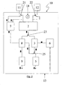
- FIG. 1 shows a 3D safety sensor 10 in measurement mode.
- the 3D security sensor 10 comprises a first camera 11, a second camera 12 and a control and evaluation unit 13.
- the control and evaluation unit 13 comprises an image evaluation unit 2, a comparator 3, a protection room violation output unit 5, a memory for protection space definition 6, a memory for test pattern 7, a disturbance detector 8, a disturbance output unit 9 and switches 21, 22, 23 and 25.
- a lighting unit 14 is provided, by means of which the spatial region in which the solid angle ranges, the cameras 11th or 12 are overlapped, can be provided, at least in some areas with a lighting structure having the properties inhomogeneous, aperiodic andsunä Republic.
- the first camera 11 is connected via the switch 21 to a first input of the image evaluation unit 2 and the second camera 12 via the switch 22 to a second input of the image evaluation unit 2.
- the output of the image evaluation unit 2 is connected via the switch 23 to a first input of the comparator 3, whose second input to the memory for protection space definition 6 connected is.
- the output of the comparator 3 is connected via the switch 25 to the protected space violation output unit 5.
- Two outputs of the memory for test pattern 7 are connected to the contact points of the switches 21, 22, which are not switched in the measuring mode, another connection is to an input of the fault detector 8.
- Other inputs of the fault detector 8 are connected to the contact points of the switches 23 and 25, which are not switched in measuring mode, connected.
- the output of the disturbance detector 8 is connected to the disturbance output unit 9 which serves to output the disturbance message.
- the images taken by the first camera 11 and the second camera 12 are supplied to the image evaluation unit 2 and processed therein into a 3D sensor image.
- This 3D sensor image is forwarded to the comparator 3, which performs a comparison with a stored in memory for shelter definition 6 3D sensor image for an undisturbed shelter. If agreement is found within the expected tolerance ranges between the recorded and the stored 3D sensor image, the protection space violation output unit 5 remains passive or outputs a signal "Protection room not injured". If 3 significant differences between the recorded and the stored sensor image found in the comparator, a violation of the shelter is detected and possibly triggered a safety function.
- the memory for test pattern 7, the disturbance detector 8 and the disturbance output unit 9 remain inoperative in this mode of operation.
- FIG. 2 shows the 3D security sensor 10 according to FIG. 1 in a first test operation.
- the switches 21, 22, 23 and 25 are each brought into a second switching position.
- the first and the second input of the image evaluation unit 2 are each connected via the switches 21, 22 to an output of the memory for the test pattern 7.
- the image evaluation unit 2 the now defined test pattern, is tested from the memory for test pattern 7 are supplied as input data.
- the result of the processing of these input data by the image evaluation unit 2 is transmitted to the disturbance detector 8, in which it is compared with the correct result.
- This correct result can also be stored in the memory for test pattern 7 or, if the comparator 3 is designed to be suitable, also in the memory for protection space definition 6 and forwarded via the comparator 3 to the interference detector 8. If, within the expected tolerance ranges, correspondence is found between the output signal of the image evaluation unit 2 fed to the disturbance detector 8 and the correct result by the disturbance detector 8, then no result "disturbance" is forwarded to the disturbance output unit 9, otherwise this result is forwarded.
- the detection of a disturbance becomes particularly precise if the correct result is stored in the memory for protection space definition 6 and in the memory for test pattern 7, since in this embodiment, if there is a match within the expected tolerance ranges of the result of the above-described comparisons in the disturbance detector 8, clearly a malfunction the image evaluation unit 2 can be closed.
- FIG. 3 shows the 3D security sensor 10 according to FIG. 1 in a second test operation, which is performed according to the inventive method cumulatively to the first test operation.
- the switches 21, 22 and 25 are as in the first test operation according to FIG. 2 switched, but switch 23 as in the measuring operation according to FIG. 1 , Accordingly, in this operating mode, the output signal that the image evaluation unit 2 generates from the test pattern signals is forwarded to the comparator 3 and compared with the definition of the protective field or the protective fields stored in the memory for protection space definition 6.
- the disturbance detector 8 is operated to check whether the comparator 3 is correctly responding to the virtual guard space violations provoked for the test. If this is the case, there is no fault. If this is not the case, a fault exists either in the image evaluation unit 2, which can be detected in the first test operation, or in the comparator 3 or in the memory for the protection space definition 6. If the memory for the protection space definition 6 is adjusted so that it can be read out separately, for example by displaying it on a display, it is also easy to decide between these components which is working incorrectly.
- the fault output unit 9 receives the signal that there is a fault from Fault detector 8 and converts this into a fault message.
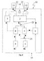
- FIG. 4 shows an embodiment of the invention, with which a third test operation can be carried out, which includes not only the actual control and evaluation electronics 13, but also the cameras 11, 12 in the functional test and is performed according to the inventive method cumulatively to the first test operation.
- the illustrated 3D safety sensor 10 largely corresponds to the in FIG. 1 illustrated 3D safety sensor.
- the image evaluation unit 2 has an additional output, via which data can be written into the memory for protection space functions 6 in a memory area reserved for this purpose.
- the illumination structure generated by the illumination unit 14 is also stored as a test pattern in the memory for test pattern 7.
- the position of the switches 21, 22 and 23 is identical to that in the case of the in FIG. 1 illustrated measuring operation, but the position of the switch 25 deviates from it, so that the output of the image evaluation unit 2 with and the output of the comparator 3 are each in communication with an input of the interference detector 8.
- the third test operation comprises the following steps: First, with the cameras 11, 12 an image is taken without illumination by the illumination unit 14 and evaluated in the image evaluation unit 2. The result of the evaluation is stored in the memory area provided for this purpose in the memory for protection space definitions 6. Subsequently, with the cameras 11, 12, a picture is taken with structured illumination by the lighting unit 14 that is now switched on, evaluated in the image evaluation unit 2 and the output of the image evaluation unit 2 an input of the comparator 3 supplied. At the other input of the comparator 3, the previously recorded image stored without illumination in the dedicated memory area of the memory for protection space definition 6 is provided, and the comparator 3 compares both images. The result of this comparison must provide the structure of the illumination, at least in some areas of the image.
- the output signal of the comparator 3 is applied to one input of the disturbance detector 8 and the illumination structure stored in the memory for test pattern 7 is applied to another input of the disturbance detector 8.
- the disturbance detector 8 compares both signals with each other; If they also do not agree in partial areas, then a fault message is output via the fault output unit 9, otherwise it is ensured that all components are functional.
Landscapes
- Engineering & Computer Science (AREA)
- General Engineering & Computer Science (AREA)
- Mechanical Engineering (AREA)
- Computer Vision & Pattern Recognition (AREA)
- Physics & Mathematics (AREA)
- General Physics & Mathematics (AREA)
- Length Measuring Devices By Optical Means (AREA)
- Alarm Systems (AREA)
- Geophysics And Detection Of Objects (AREA)
Claims (7)
- °) Capteur de sécurité en 3D (10) comprenant :une première caméra (11) et une seconde caméra (12), alignées pour que leurs plages d'angle solide se chevauchent, et une unité de commande etd'exploitation (13) comprenant une unité d'exploitation d'image (2), un comparateur (3), une mémoire de définition de l'espace protégé (6), etune unité de sortie, d'atteinte à l'espace protégé (5),dans lequel- l'unité de commande et d'exploitation (13) comprend en plus une mémoire de motif de test (7), un détecteur d'incident (8) et une unité de sortie d'incident (9),- des liaisons de transmission de signaux sont prévues au moins entre une sortie de la mémoire de motif de test (7) et une entrée du détecteur d'incident (8), entre une sortie du détecteur d'incident (8) et une entrée de l'unité de sortie d'incident (9), ainsi qu'entre une sortie de la mémoire des définitions de l'espace protégé (6) et une entrée du comparateur (3),- deux entrées de l'unité d'exploitation d'image (2) peuvent être reliées respectivement par des commutateurs (21, 22) chacune à la sortie d'une caméra (11, 12) ou à la sortie de la mémoire de motif de test (7),- une sortie de l'unité d'exploitation d'image (2) est respectivement reliée par un commutateur (23) à une entrée du comparateur (3) ou à une entrée du détecteur d'incident (8) et/ou une sortie du comparateur (3) est reliée respectivement par un commutateur (25) à une entrée de l'unité de sortie, d'atteinte à l'espace protégé (5) ou à une entrée du détecteur d'incident (8).
- °) Capteur de sécurité en 3D selon la revendication 1,
dans lequel
en plus, il est prévu une liaison de signal entre une sortie de l'unité d'exploitation d'image (2) et une plage de la mémoire des définitions de l'espace protégé (6), pour enregistrer les résultats de l'exploitation de l'unité d'exploitation d'image (2) dans une plage prédéterminée de la mémoire des définitions de l'espace protégé (6). - °) Capteur de sécurité en 3D selon la revendication 1 ou 2,
dans lequel
en plus, il est prévu une unité d'éclairage (14) permettant d'appliquer à la plage d'espace dans laquelle les plages d'angle solide saisies par les caméras (11, 12) se chevauchent, au moins dans des zones partielles, d'une structure d'éclairage ayant les propriétés d'être non-homogène, apériodique et non-analogue avec elle-même. - °) Capteur de sécurité en 3D selon les revendications précédentes,
dans lequel
l'unité d'exploitation d'image (2) est complètement réalisée sous la forme de circuit. - °) Procédé de tests d'un capteur de sécurité en 3D selon une revendication précédente,
selon lequel- le capteur de sécurité en 3D est installé pour que les images prises par une première caméra (11) et une seconde caméra (12), soient traitées par une unité d'exploitation d'image (2) pour donner une image de capteur en 3D,- le procédé comprenant les étapes suivantes :* enregistrer des motifs de test dans une mémoire de motif de test (7),* appliquer des motifs de test comme données d'entrée à une première et à une seconde entrée de l'unité d'exploitation d'image (2) à la place des données de la première et de la seconde caméra (11, 12),* vérifier le fonctionnement correct de l'unité d'exploitation d'image (2) par comparaison des résultats du traitement de ces données d'image par l'unité d'exploitation d'image (2) avec une image de consigne enregistrée dans la mémoire de motif de test (7), à l'aide d'un détecteur d'incident (8), et* signaler un incident par l'unité de sortie d'incident (9) si l'on constate une différence dépassant les tolérances acceptées. - °) Procédé selon la revendication 5, comprenant en outre les étapes suivantes :- vérifier le fonctionnement du comparateur (3) en surveillant si un motif de test fourni par la mémoire de motif de test (7) à l'unité d'exploitation d'image (2) et composé d'objets de dimension et de nombre nécessaire pour porter atteinte au domaine protégé, produit la réaction du comparateur (3) définie pour cette atteinte au domaine protégé, par le détecteur d'incident (8), et- signaler un incident par l'unité de sortie d'incident (9) si cela n'est pas le cas.
- °) Procédé selon la revendication 5 ou 6, comprenant en outre les étapes suivantes :- fournir un motif d'éclairage à la mémoire de motif de test (7),- saisir d'une première image d'un espace protégé, à surveiller, sans l'éclairage structuré par le motif d'éclairage,- exploiter la première image prise dans l'unité d'exploitation d'image (2),- enregistrer la première image exploitée dans une zone prévue à cet effet de la mémoire des définitions d'espace protégé (6),- prendre une seconde image d'un espace protégé à surveiller avec un éclairage structuré,- exploiter la seconde image prise dans l'unité d'exploitation d'image (2),- comparer la seconde image exploitée à une première image exploitée, fournie par la mémoire des définitions d'espace protégé (6) dans le comparateur (3),- comparer le résultat du comparateur (3) à la structure d'éclairage fournie par la mémoire de motif de test (7) dans le détecteur d'incident (8), et- signaler un incident par l'unité de sortie d'incident (9) si la comparaison ne donne aucune concordance même dans des zones partielles.
Priority Applications (3)
| Application Number | Priority Date | Filing Date | Title |
|---|---|---|---|
| EP07014270A EP2017571B1 (fr) | 2007-07-20 | 2007-07-20 | Capteur de sécurité en 3D et procédé destiné à tester un capteur de sécurité en 3D |
| DE502007002747T DE502007002747D1 (de) | 2007-07-20 | 2007-07-20 | 3D-Sicherheits-Sensor und Verfahren zum Testen eines 3D-Sicherheits-Sensors |
| AT07014270T ATE456783T1 (de) | 2007-07-20 | 2007-07-20 | 3d-sicherheits-sensor und verfahren zum testen eines 3d-sicherheits-sensors |
Applications Claiming Priority (1)
| Application Number | Priority Date | Filing Date | Title |
|---|---|---|---|
| EP07014270A EP2017571B1 (fr) | 2007-07-20 | 2007-07-20 | Capteur de sécurité en 3D et procédé destiné à tester un capteur de sécurité en 3D |
Publications (2)
| Publication Number | Publication Date |
|---|---|
| EP2017571A1 EP2017571A1 (fr) | 2009-01-21 |
| EP2017571B1 true EP2017571B1 (fr) | 2010-01-27 |
Family
ID=38669529
Family Applications (1)
| Application Number | Title | Priority Date | Filing Date |
|---|---|---|---|
| EP07014270A Not-in-force EP2017571B1 (fr) | 2007-07-20 | 2007-07-20 | Capteur de sécurité en 3D et procédé destiné à tester un capteur de sécurité en 3D |
Country Status (3)
| Country | Link |
|---|---|
| EP (1) | EP2017571B1 (fr) |
| AT (1) | ATE456783T1 (fr) |
| DE (1) | DE502007002747D1 (fr) |
Families Citing this family (1)
| Publication number | Priority date | Publication date | Assignee | Title |
|---|---|---|---|---|
| EP2818824B1 (fr) * | 2013-06-28 | 2015-09-16 | Sick Ag | Appareil comprenant un capteur optoélectronique 3D et procédé de réconaissance d'objets |
Family Cites Families (5)
| Publication number | Priority date | Publication date | Assignee | Title |
|---|---|---|---|---|
| DE59804862D1 (de) | 1997-09-15 | 2002-08-29 | Rms Kleine Gmbh Vertrieb Elekt | Verfahren und Vorrichtung zur optischen Überwachung eines Raumbereichs |
| DE10017344C1 (de) * | 2000-04-07 | 2001-11-29 | Pilz Gmbh & Co | Verfahren und Vorrichtung zum Überprüfen der Funktionssicherheit einer Bildaufnahmeeinheit |
| EP1543270B8 (fr) | 2002-09-24 | 2013-01-23 | Pilz GmbH & Co. KG | Procede et dispositif pour securiser une zone de risque |
| DE10253501A1 (de) | 2002-11-16 | 2004-05-27 | Robert Bosch Gmbh | Bildgeber |
| ITTO20050163A1 (it) * | 2005-03-15 | 2006-09-16 | K A Schmersal Gmbh | Sistema di visione di sicurezza con verifica della capacita' di rilevamento |
-
2007
- 2007-07-20 DE DE502007002747T patent/DE502007002747D1/de active Active
- 2007-07-20 AT AT07014270T patent/ATE456783T1/de active
- 2007-07-20 EP EP07014270A patent/EP2017571B1/fr not_active Not-in-force
Also Published As
| Publication number | Publication date |
|---|---|
| EP2017571A1 (fr) | 2009-01-21 |
| DE502007002747D1 (de) | 2010-03-18 |
| ATE456783T1 (de) | 2010-02-15 |
Similar Documents
| Publication | Publication Date | Title |
|---|---|---|
| EP2095008B1 (fr) | Procédé et dispositif de surveillance d'un espace à trois dimensions | |
| EP1949143B1 (fr) | Dispositif et procede pour surveiller une zone de l'espace, en particulier pour securiser une zone a risques d'une installation automatisee | |
| DE102007025373B3 (de) | Visuelle Überwachung mit Entfernungsbestimmung und Plausibilitätsprüfung anhand von Bildgrößen | |
| EP3200122B1 (fr) | Capteur optoelectronique et procede de reconnaissance fiable d'objets de taille minimum | |
| EP1933167B1 (fr) | Capteur optoélectronique et procédé correspondant de détection et de détermination de la distance d'un objet | |
| EP2025991B1 (fr) | Dispositif et procédé de surveillance tridimensionnelle d'un domaine spatial doté d'au moins deux capteurs d'images | |
| DE10143504A1 (de) | Überwachungsverfahren und optoelektronischer Sensor | |
| WO2001013029A1 (fr) | Dispositif pour proteger une zone dangereuse, notamment une zone dangereuse d'une machine fonctionnant de maniere automatisee | |
| WO2004029502A1 (fr) | Procede et dispositif pour securiser une zone de risque | |
| EP2019281B1 (fr) | Procédé destiné au fonctionnement d'un capteur en 3D | |
| EP3220164B1 (fr) | Procédé de fonctionnement d'un capteur écartométrique de surveillance et capteur écartométrique de surveillance | |
| EP2275989A1 (fr) | Caméra 3D stéréoscopique | |
| EP1993081A1 (fr) | Dispositif de capteur optoélectronique et procédé de surveillance d'une zone de surveillance | |
| DE102006041307A1 (de) | Opto-elektronische Sensoranordnung | |
| DE10033608A1 (de) | Verfahren und Vorrichtung zum Absichern eines Gefahrenbereichs, insbesondere des Gefahrenbereichs einer automatisiert arbeitenden Maschine | |
| DE10327388C5 (de) | Schutzeinrichtung | |
| EP3217195B1 (fr) | Capteur optique | |
| DE102020114488B3 (de) | Optoelektronischer Sicherheitssensor und Verfahren zur Absicherung einer Maschine | |
| EP2017571B1 (fr) | Capteur de sécurité en 3D et procédé destiné à tester un capteur de sécurité en 3D | |
| DE102009026091A1 (de) | Verfahren und System zur Überwachung eines dreidimensionalen Raumbereichs mit mehreren Kameras | |
| EP3651458B1 (fr) | Caméra stéréo sécurisée et procédé de vérification de la capacité de fonctionnement des capteurs d'image | |
| DE19964492B4 (de) | Vorrichtung zur Absicherung eines Gefahrenbereichs, insbesondere des Gefahrenbereichs einer automatisiert arbeitenden Maschine | |
| EP1722151B1 (fr) | Dispositif pour sécuriser une zone dangereuse | |
| EP3496398B1 (fr) | Caméra stéréo sécurisée et procédé de vérification de la capacité de fonctionnement des capteurs d'image | |
| DE102017004030B4 (de) | Verfahren und Vorrichtung zum Sichern eines Arbeitsraums |
Legal Events
| Date | Code | Title | Description |
|---|---|---|---|
| PUAI | Public reference made under article 153(3) epc to a published international application that has entered the european phase |
Free format text: ORIGINAL CODE: 0009012 |
|
| 17P | Request for examination filed |
Effective date: 20080405 |
|
| AK | Designated contracting states |
Kind code of ref document: A1 Designated state(s): AT BE BG CH CY CZ DE DK EE ES FI FR GB GR HU IE IS IT LI LT LU LV MC MT NL PL PT RO SE SI SK TR |
|
| AX | Request for extension of the european patent |
Extension state: AL BA HR MK RS |
|
| AKX | Designation fees paid |
Designated state(s): AT BE BG CH CY CZ DE DK EE ES FI FR GB GR HU IE IS IT LI LT LU LV MC MT NL PL PT RO SE SI SK TR |
|
| GRAP | Despatch of communication of intention to grant a patent |
Free format text: ORIGINAL CODE: EPIDOSNIGR1 |
|
| GRAS | Grant fee paid |
Free format text: ORIGINAL CODE: EPIDOSNIGR3 |
|
| GRAA | (expected) grant |
Free format text: ORIGINAL CODE: 0009210 |
|
| AK | Designated contracting states |
Kind code of ref document: B1 Designated state(s): AT BE BG CH CY CZ DE DK EE ES FI FR GB GR HU IE IS IT LI LT LU LV MC MT NL PL PT RO SE SI SK TR |
|
| REG | Reference to a national code |
Ref country code: GB Ref legal event code: FG4D Free format text: NOT ENGLISH |
|
| REG | Reference to a national code |
Ref country code: CH Ref legal event code: EP |
|
| REG | Reference to a national code |
Ref country code: IE Ref legal event code: FG4D |
|
| REF | Corresponds to: |
Ref document number: 502007002747 Country of ref document: DE Date of ref document: 20100318 Kind code of ref document: P |
|
| REG | Reference to a national code |
Ref country code: NL Ref legal event code: VDEP Effective date: 20100127 |
|
| LTIE | Lt: invalidation of european patent or patent extension |
Effective date: 20100127 |
|
| PG25 | Lapsed in a contracting state [announced via postgrant information from national office to epo] |
Ref country code: ES Free format text: LAPSE BECAUSE OF FAILURE TO SUBMIT A TRANSLATION OF THE DESCRIPTION OR TO PAY THE FEE WITHIN THE PRESCRIBED TIME-LIMIT Effective date: 20100508 Ref country code: IS Free format text: LAPSE BECAUSE OF FAILURE TO SUBMIT A TRANSLATION OF THE DESCRIPTION OR TO PAY THE FEE WITHIN THE PRESCRIBED TIME-LIMIT Effective date: 20100527 Ref country code: NL Free format text: LAPSE BECAUSE OF FAILURE TO SUBMIT A TRANSLATION OF THE DESCRIPTION OR TO PAY THE FEE WITHIN THE PRESCRIBED TIME-LIMIT Effective date: 20100127 Ref country code: PT Free format text: LAPSE BECAUSE OF FAILURE TO SUBMIT A TRANSLATION OF THE DESCRIPTION OR TO PAY THE FEE WITHIN THE PRESCRIBED TIME-LIMIT Effective date: 20100527 Ref country code: LT Free format text: LAPSE BECAUSE OF FAILURE TO SUBMIT A TRANSLATION OF THE DESCRIPTION OR TO PAY THE FEE WITHIN THE PRESCRIBED TIME-LIMIT Effective date: 20100127 |
|
| REG | Reference to a national code |
Ref country code: IE Ref legal event code: FD4D |
|
| PG25 | Lapsed in a contracting state [announced via postgrant information from national office to epo] |
Ref country code: FI Free format text: LAPSE BECAUSE OF FAILURE TO SUBMIT A TRANSLATION OF THE DESCRIPTION OR TO PAY THE FEE WITHIN THE PRESCRIBED TIME-LIMIT Effective date: 20100127 Ref country code: SI Free format text: LAPSE BECAUSE OF FAILURE TO SUBMIT A TRANSLATION OF THE DESCRIPTION OR TO PAY THE FEE WITHIN THE PRESCRIBED TIME-LIMIT Effective date: 20100127 Ref country code: PL Free format text: LAPSE BECAUSE OF FAILURE TO SUBMIT A TRANSLATION OF THE DESCRIPTION OR TO PAY THE FEE WITHIN THE PRESCRIBED TIME-LIMIT Effective date: 20100127 Ref country code: LV Free format text: LAPSE BECAUSE OF FAILURE TO SUBMIT A TRANSLATION OF THE DESCRIPTION OR TO PAY THE FEE WITHIN THE PRESCRIBED TIME-LIMIT Effective date: 20100127 |
|
| PG25 | Lapsed in a contracting state [announced via postgrant information from national office to epo] |
Ref country code: IE Free format text: LAPSE BECAUSE OF FAILURE TO SUBMIT A TRANSLATION OF THE DESCRIPTION OR TO PAY THE FEE WITHIN THE PRESCRIBED TIME-LIMIT Effective date: 20100127 Ref country code: GR Free format text: LAPSE BECAUSE OF FAILURE TO SUBMIT A TRANSLATION OF THE DESCRIPTION OR TO PAY THE FEE WITHIN THE PRESCRIBED TIME-LIMIT Effective date: 20100428 Ref country code: CY Free format text: LAPSE BECAUSE OF FAILURE TO SUBMIT A TRANSLATION OF THE DESCRIPTION OR TO PAY THE FEE WITHIN THE PRESCRIBED TIME-LIMIT Effective date: 20100127 Ref country code: SE Free format text: LAPSE BECAUSE OF FAILURE TO SUBMIT A TRANSLATION OF THE DESCRIPTION OR TO PAY THE FEE WITHIN THE PRESCRIBED TIME-LIMIT Effective date: 20100127 Ref country code: RO Free format text: LAPSE BECAUSE OF FAILURE TO SUBMIT A TRANSLATION OF THE DESCRIPTION OR TO PAY THE FEE WITHIN THE PRESCRIBED TIME-LIMIT Effective date: 20100127 Ref country code: EE Free format text: LAPSE BECAUSE OF FAILURE TO SUBMIT A TRANSLATION OF THE DESCRIPTION OR TO PAY THE FEE WITHIN THE PRESCRIBED TIME-LIMIT Effective date: 20100127 |
|
| PG25 | Lapsed in a contracting state [announced via postgrant information from national office to epo] |
Ref country code: SK Free format text: LAPSE BECAUSE OF FAILURE TO SUBMIT A TRANSLATION OF THE DESCRIPTION OR TO PAY THE FEE WITHIN THE PRESCRIBED TIME-LIMIT Effective date: 20100127 Ref country code: CZ Free format text: LAPSE BECAUSE OF FAILURE TO SUBMIT A TRANSLATION OF THE DESCRIPTION OR TO PAY THE FEE WITHIN THE PRESCRIBED TIME-LIMIT Effective date: 20100127 Ref country code: BG Free format text: LAPSE BECAUSE OF FAILURE TO SUBMIT A TRANSLATION OF THE DESCRIPTION OR TO PAY THE FEE WITHIN THE PRESCRIBED TIME-LIMIT Effective date: 20100427 |
|
| PLBE | No opposition filed within time limit |
Free format text: ORIGINAL CODE: 0009261 |
|
| STAA | Information on the status of an ep patent application or granted ep patent |
Free format text: STATUS: NO OPPOSITION FILED WITHIN TIME LIMIT |
|
| 26N | No opposition filed |
Effective date: 20101028 |
|
| BERE | Be: lapsed |
Owner name: SICK A.G. Effective date: 20100731 |
|
| PG25 | Lapsed in a contracting state [announced via postgrant information from national office to epo] |
Ref country code: DK Free format text: LAPSE BECAUSE OF FAILURE TO SUBMIT A TRANSLATION OF THE DESCRIPTION OR TO PAY THE FEE WITHIN THE PRESCRIBED TIME-LIMIT Effective date: 20100127 |
|
| PG25 | Lapsed in a contracting state [announced via postgrant information from national office to epo] |
Ref country code: MC Free format text: LAPSE BECAUSE OF NON-PAYMENT OF DUE FEES Effective date: 20100731 |
|
| PG25 | Lapsed in a contracting state [announced via postgrant information from national office to epo] |
Ref country code: IT Free format text: LAPSE BECAUSE OF FAILURE TO SUBMIT A TRANSLATION OF THE DESCRIPTION OR TO PAY THE FEE WITHIN THE PRESCRIBED TIME-LIMIT Effective date: 20100127 |
|
| REG | Reference to a national code |
Ref country code: FR Ref legal event code: ST Effective date: 20110331 |
|
| PG25 | Lapsed in a contracting state [announced via postgrant information from national office to epo] |
Ref country code: FR Free format text: LAPSE BECAUSE OF NON-PAYMENT OF DUE FEES Effective date: 20100802 |
|
| PG25 | Lapsed in a contracting state [announced via postgrant information from national office to epo] |
Ref country code: BE Free format text: LAPSE BECAUSE OF NON-PAYMENT OF DUE FEES Effective date: 20100731 |
|
| PG25 | Lapsed in a contracting state [announced via postgrant information from national office to epo] |
Ref country code: MT Free format text: LAPSE BECAUSE OF FAILURE TO SUBMIT A TRANSLATION OF THE DESCRIPTION OR TO PAY THE FEE WITHIN THE PRESCRIBED TIME-LIMIT Effective date: 20100127 |
|
| REG | Reference to a national code |
Ref country code: CH Ref legal event code: PL |
|
| PG25 | Lapsed in a contracting state [announced via postgrant information from national office to epo] |
Ref country code: CH Free format text: LAPSE BECAUSE OF NON-PAYMENT OF DUE FEES Effective date: 20110731 Ref country code: LI Free format text: LAPSE BECAUSE OF NON-PAYMENT OF DUE FEES Effective date: 20110731 |
|
| PG25 | Lapsed in a contracting state [announced via postgrant information from national office to epo] |
Ref country code: LU Free format text: LAPSE BECAUSE OF NON-PAYMENT OF DUE FEES Effective date: 20100720 Ref country code: HU Free format text: LAPSE BECAUSE OF FAILURE TO SUBMIT A TRANSLATION OF THE DESCRIPTION OR TO PAY THE FEE WITHIN THE PRESCRIBED TIME-LIMIT Effective date: 20100728 |
|
| PG25 | Lapsed in a contracting state [announced via postgrant information from national office to epo] |
Ref country code: TR Free format text: LAPSE BECAUSE OF FAILURE TO SUBMIT A TRANSLATION OF THE DESCRIPTION OR TO PAY THE FEE WITHIN THE PRESCRIBED TIME-LIMIT Effective date: 20100127 |
|
| REG | Reference to a national code |
Ref country code: AT Ref legal event code: MM01 Ref document number: 456783 Country of ref document: AT Kind code of ref document: T Effective date: 20120731 |
|
| PG25 | Lapsed in a contracting state [announced via postgrant information from national office to epo] |
Ref country code: AT Free format text: LAPSE BECAUSE OF NON-PAYMENT OF DUE FEES Effective date: 20120731 |
|
| PGFP | Annual fee paid to national office [announced via postgrant information from national office to epo] |
Ref country code: GB Payment date: 20150724 Year of fee payment: 9 |
|
| GBPC | Gb: european patent ceased through non-payment of renewal fee |
Effective date: 20160720 |
|
| PG25 | Lapsed in a contracting state [announced via postgrant information from national office to epo] |
Ref country code: GB Free format text: LAPSE BECAUSE OF NON-PAYMENT OF DUE FEES Effective date: 20160720 |
|
| PGFP | Annual fee paid to national office [announced via postgrant information from national office to epo] |
Ref country code: DE Payment date: 20200723 Year of fee payment: 14 |
|
| REG | Reference to a national code |
Ref country code: DE Ref legal event code: R119 Ref document number: 502007002747 Country of ref document: DE |
|
| PG25 | Lapsed in a contracting state [announced via postgrant information from national office to epo] |
Ref country code: DE Free format text: LAPSE BECAUSE OF NON-PAYMENT OF DUE FEES Effective date: 20220201 |