EP1061489A1 - Détecteur d'intrusion avec dispositif de surveillance contre un sabotage - Google Patents
Détecteur d'intrusion avec dispositif de surveillance contre un sabotage Download PDFInfo
- Publication number
- EP1061489A1 EP1061489A1 EP99110848A EP99110848A EP1061489A1 EP 1061489 A1 EP1061489 A1 EP 1061489A1 EP 99110848 A EP99110848 A EP 99110848A EP 99110848 A EP99110848 A EP 99110848A EP 1061489 A1 EP1061489 A1 EP 1061489A1
- Authority
- EP
- European Patent Office
- Prior art keywords
- infrared
- detector
- receiver
- radiation
- transmitter
- Prior art date
- Legal status (The legal status is an assumption and is not a legal conclusion. Google has not performed a legal analysis and makes no representation as to the accuracy of the status listed.)
- Granted
Links
- 238000012544 monitoring process Methods 0.000 title claims description 18
- 230000005855 radiation Effects 0.000 claims abstract description 51
- 238000011156 evaluation Methods 0.000 claims description 20
- 238000002604 ultrasonography Methods 0.000 claims description 20
- 239000000463 material Substances 0.000 claims description 10
- 230000003287 optical effect Effects 0.000 claims description 10
- 238000001514 detection method Methods 0.000 claims description 4
- 238000012806 monitoring device Methods 0.000 claims description 4
- 239000007921 spray Substances 0.000 description 12
- 230000000873 masking effect Effects 0.000 description 9
- 238000000034 method Methods 0.000 description 5
- 230000005540 biological transmission Effects 0.000 description 3
- 238000012937 correction Methods 0.000 description 3
- 230000001419 dependent effect Effects 0.000 description 3
- 230000009977 dual effect Effects 0.000 description 3
- 230000000694 effects Effects 0.000 description 3
- 239000002245 particle Substances 0.000 description 3
- 238000005507 spraying Methods 0.000 description 3
- 230000036961 partial effect Effects 0.000 description 2
- -1 polyethylene Polymers 0.000 description 2
- 238000012549 training Methods 0.000 description 2
- 239000004698 Polyethylene Substances 0.000 description 1
- 239000004743 Polypropylene Substances 0.000 description 1
- 230000006978 adaptation Effects 0.000 description 1
- 238000006243 chemical reaction Methods 0.000 description 1
- 230000000295 complement effect Effects 0.000 description 1
- 230000003247 decreasing effect Effects 0.000 description 1
- 230000006735 deficit Effects 0.000 description 1
- 238000013461 design Methods 0.000 description 1
- 238000010586 diagram Methods 0.000 description 1
- 238000002845 discoloration Methods 0.000 description 1
- 238000004519 manufacturing process Methods 0.000 description 1
- 239000003973 paint Substances 0.000 description 1
- 229920000573 polyethylene Polymers 0.000 description 1
- 229920001155 polypropylene Polymers 0.000 description 1
- 230000002829 reductive effect Effects 0.000 description 1
- 230000000284 resting effect Effects 0.000 description 1
- 239000000779 smoke Substances 0.000 description 1
- 239000007779 soft material Substances 0.000 description 1
- 239000004071 soot Substances 0.000 description 1
- 230000003595 spectral effect Effects 0.000 description 1
- 238000001228 spectrum Methods 0.000 description 1
- 230000001960 triggered effect Effects 0.000 description 1
Images
Classifications
-
- G—PHYSICS
- G08—SIGNALLING
- G08B—SIGNALLING OR CALLING SYSTEMS; ORDER TELEGRAPHS; ALARM SYSTEMS
- G08B29/00—Checking or monitoring of signalling or alarm systems; Prevention or correction of operating errors, e.g. preventing unauthorised operation
- G08B29/18—Prevention or correction of operating errors
- G08B29/183—Single detectors using dual technologies
-
- G—PHYSICS
- G08—SIGNALLING
- G08B—SIGNALLING OR CALLING SYSTEMS; ORDER TELEGRAPHS; ALARM SYSTEMS
- G08B13/00—Burglar, theft or intruder alarms
- G08B13/16—Actuation by interference with mechanical vibrations in air or other fluid
- G08B13/1609—Actuation by interference with mechanical vibrations in air or other fluid using active vibration detection systems
- G08B13/1645—Actuation by interference with mechanical vibrations in air or other fluid using active vibration detection systems using ultrasonic detection means and other detection means, e.g. microwave or infrared radiation
-
- G—PHYSICS
- G08—SIGNALLING
- G08B—SIGNALLING OR CALLING SYSTEMS; ORDER TELEGRAPHS; ALARM SYSTEMS
- G08B13/00—Burglar, theft or intruder alarms
- G08B13/18—Actuation by interference with heat, light, or radiation of shorter wavelength; Actuation by intruding sources of heat, light, or radiation of shorter wavelength
- G08B13/181—Actuation by interference with heat, light, or radiation of shorter wavelength; Actuation by intruding sources of heat, light, or radiation of shorter wavelength using active radiation detection systems
-
- G—PHYSICS
- G08—SIGNALLING
- G08B—SIGNALLING OR CALLING SYSTEMS; ORDER TELEGRAPHS; ALARM SYSTEMS
- G08B13/00—Burglar, theft or intruder alarms
- G08B13/18—Actuation by interference with heat, light, or radiation of shorter wavelength; Actuation by intruding sources of heat, light, or radiation of shorter wavelength
- G08B13/189—Actuation by interference with heat, light, or radiation of shorter wavelength; Actuation by intruding sources of heat, light, or radiation of shorter wavelength using passive radiation detection systems
- G08B13/19—Actuation by interference with heat, light, or radiation of shorter wavelength; Actuation by intruding sources of heat, light, or radiation of shorter wavelength using passive radiation detection systems using infrared-radiation detection systems
-
- G—PHYSICS
- G08—SIGNALLING
- G08B—SIGNALLING OR CALLING SYSTEMS; ORDER TELEGRAPHS; ALARM SYSTEMS
- G08B29/00—Checking or monitoring of signalling or alarm systems; Prevention or correction of operating errors, e.g. preventing unauthorised operation
- G08B29/02—Monitoring continuously signalling or alarm systems
- G08B29/04—Monitoring of the detection circuits
- G08B29/046—Monitoring of the detection circuits prevention of tampering with detection circuits
Definitions
- the present invention relates to an intrusion detector with and in a housing arranged infrared part, with an infrared sensor, one provided in the housing wall Detector window for the passage of infrared radiation from the outside to the infrared sensor, a means for bundling the infrared radiation incident through the detector window the infrared sensor and with one comprising an infrared transmitter and an infrared receiver Sabotage monitoring device.
- Such sabotage monitoring devices also referred to as anti-mask devices, as for example in EP-A-0 186 226, in EP-A-0 499 177 and in EP-A-0 556 898 are used to identify the two types of cover for the detector, that is the coverage of the detector in a certain, possibly only slight, Distance from the detector window, and the immediate coverage of the detector window by, for example Covering with a film or spraying with an infrared-opaque spray, such as paint spray.
- the first type of coverage is subsequently referred to as remote coverage and the second is called a spray cover, with remote cover being a cover at a distance of a few millimeters up to a maximum of about 15 cm from the detector window.
- the known devices for sabotage monitoring are single or two-channel systems built up.
- two-channel systems such as that described in EP-A-0 186 226 Device, sends a first infrared transmitter, which is arranged inside the detector, Infrared radiation in the monitoring room in front of the detector and a first receiver measures the radiation reflected from the surveillance room.
- a second one, on the outside of the detector arranged infrared transmitter sends radiation through the detector window to a second Receiver that measures the incident radiation from the second transmitter.
- the first transmitter and the first receiver form a channel for monitoring attempts at sabotage in the manner of remote coverage and the second transmitter and the second receiver form a channel Monitoring of sabotage attempts in the manner of spray coverage.
- the device for sabotage monitoring contains only one infrared transmitter and only one infrared receiver, the transmitter is arranged on the outside and the receiver inside the detector. The transmitter sends infrared radiation on the one hand into the monitoring room in front of the detector and on the other hand through the detector window onto the receiver.
- a similar single-channel system is in EP-A-0 556 898.
- the detector window to coincide with the Time discolors and possibly also its transmission properties for infrared radiation changes.
- the latter can be a technical impairment to the functionality of the detector Be a disadvantage; in any case, the discoloration of the detector window is aesthetic Disadvantage because over time the detector window differs from the detector housing Color assumes.
- the diffraction-optical grating structure is only for detection suitable from spray cover, but not from remote cover.
- the invention now aims to provide an intrusion detector with a device for tamper monitoring be specified, which neither the creative freedom for the training of the Detector housing constricts, still impairing functional reliability or the exterior Appearance of a detector equipped with such a device. Furthermore both types of sabotage, namely the remote cover and the spray cover, can be recognized in so-called real-time mode if possible.
- Real-time mode is a process in which only sufficiently large and sufficient stable changes trigger a sabotage alarm which, when the signals return to the Normal state is automatically withdrawn.
- This mode reacts slower than the second known method, the so-called proximity latch mode, has the advantage automatic alarm cancellation.
- the solution according to the invention is characterized in that the infrared transmitter and the Infrared receivers are arranged inside the housing that the detector window for Radiation emitted by the infrared transmitter is permeable, and that the monitoring of sabotage of the detector by measuring the from the inside of the detector window and the the surrounding space to the infrared receiver reflected portion of said radiation he follows.
- the arrangement of the transmitter and receiver under the detector window is not only aesthetic Considerations and avoiding the risk of excessive and difficult to remove Particle deposits on the detector window have the further advantage that not from the outside it can be seen that the detector has a device for monitoring sabotage.
- dark material means a material that is below one Well absorbed wavelength of about 4 ⁇ m.
- the reflective layer is in the visible range transparent and allows infrared radiation of short wavelengths, preferably below 4 - 7 ⁇ m through, so that it can get into the dark carrier layer, where it is absorbed.
- the mirror made of dark material ensures that as little interference light as possible on the sensor and falls on the infrared receiver, and is therefore a prerequisite that the detector does both types of sabotage, Remote coverage and spray coverage, can detect in real-time mode.
- a third preferred embodiment of the intrusion detector according to the invention is thereby characterized in that the detector consists of an additional transmitter and an additional Receiver existing additional part that an evaluation of the signal of the additional Receiver takes place in two frequency ranges, one of which for movements in the Surveillance room and the other is characteristic of a cover of the detector, and that a common evaluation circuit is provided for the additional part and the infrared part is.
- the additional part is preferably an ultrasonic part with an ultrasonic transmitter and a Ultrasonic receiver or a microwave part with a microwave transmitter and a microwave receiver.
- a further preferred embodiment of the intrusion detector according to the invention is thereby characterized in that evaluation circuit downstream of the infrared sensor PIR channel, an anti-mask channel downstream of the infrared receiver and one second receiver downstream US channel with US antimask channel and one to the outputs of the above-mentioned channels connected logic level for the combined evaluation which has signals from these channels.
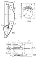
- Fig. 1 shows a longitudinal section through an intrusion detector according to the invention in the direction perpendicular to the rear wall or floor thereof, the floor being removed
- FIG. 2 shows a partial view from behind, the mirror for bundling the incident Infrared radiation is removed from the detector.
- the intrusion detector shown is a so-called Dual detector, which consists of the combination of a passive infrared detector and one with there is an ultrasound detector connected via an intelligent link.
- the infrared part reacts to the body radiation of a person in the infrared spectral range and Ultrasound part on the frequency shift of the caused by the Doppler effect a moving intruder reflected ultrasound.
- the intrusion detector can sabotage only one of the detectors.
- a Such sabotage usually takes place on the infrared detector in the form of the introduction to the description mentioned types of coverage remote coverage or spray coverage because of decommissioning of the ultrasound part of the whole detector would have to be covered, which is immediately recognizable would.
- the device used in the intrusion detector described below Sabotage monitoring also serves to detect sabotage on the infrared detector and can therefore not only be used in conjunction with dual detectors but also with passive infrared detectors may be used, in which case minor adaptations may be required can.
- the intrusion detector consists of a two-part housing with a base (not shown) and cover 1, a detector window 2 provided in the cover 1 for the Passage of the infrared radiation falling from the room to be monitored onto the detector Detector interior, a circuit board 3 arranged in the interior of the detector, on which, among other things, a Infrared sensor 4, an ultrasound transmitter 5, an ultrasound receiver 6 and an evaluation circuit 7 are arranged, and with a mirror 8 also arranged in the interior of the detector Focusing of the infrared radiation incident through the detector window 2 onto the infrared sensor 4.
- a pin element 9 of an electrical connector arranged, the socket element is located in the housing bottom.
- the entrance window 2 consists for example of polyethylene or polypropylene and is for Radiation in the wavelength range from about 5 to 15 ⁇ m and in the range around 0.9 ⁇ m permeable.
- the mirror 8 is designed such that it absorbs radiation in the near infrared and Reflected body radiation.
- a mirror with a day layer is particularly suitable for this made of dark material and a reflective layer applied on it, which for interference radiation below the wavelength range mentioned is transparent and radiation from this wavelength range strongly reflected.
- EP-A-0 303 913 referenced and with regard to the mirror material to EP-A-0 707 294.
- the entrance window 2 can be designed as a Fresnel lens and instead of the mirror 8, the infrared radiation on the Focus infrared sensor 4.
- the ultrasonic transmitter 5 emits ultrasound at a frequency of over 20 kHz through an opening 10 in the housing cover 1 in the interstitial space in front of the detector, and the ultrasonic receiver 6 takes the reflected from the surveillance room and through a window 11 in the housing cover 1 on the receiver 6 ultrasound and leads the evaluation circuit 7 a corresponding signal. While stationary objects only use ultrasound reflecting the transmission frequency, a moving object causes a frequency shift after the Doppler effect.
- the evaluation circuit 7 triggers an alarm signal when this Frequency shift corresponds to the values typical for a moving person and if at the same time the infrared sensor 4 is infrared radiation typical of a human being receives.
- the intrusion detector shown is with a so-called anti-mask device for detection of processes or optical changes immediately before the detector (so-called remote coverage) and changes in the optical properties of the entrance window 2, in particular equipped by its spraying (so-called spray cover).
- Such masking is used to manipulate the detector so that no infrared radiation can reach the infrared sensor so that unauthorized persons can no longer be detected and can move freely in the monitored room.
- Masking or sabotage will mostly perpetrated during the disarming of the detector when it is in a stand-by mode is switched on and people in the monitored room do not trigger an alarm.
- the detector should be able to automatically detect such masking, specifically preferably at the time of masking or at the latest when the detector is armed or the plant.
- the device for sabotage monitoring is designed so that with a single channel both masking methods can be reliably recognized.
- an infrared transmitter 12 is arranged on both sides of the infrared sensor 4 and symmetrically to the latter.
- an infrared receiver 13 is provided in the middle between the two infrared transmitters 12 and below the infrared sensor 4 is on the board 3 .
- This is inclined at a certain angle Board 3 arranged, the angle of inclination is selected so that that of the infrared transmitters 12 emitted radiation to a certain extent, from the optical properties of the Detector window dependent part, is reflected on the infrared receiver 13.
- the infrared receiver 13 is preferably formed by a so-called Pn diode.
- the signal of the infrared receiver 13 with an alarm threshold and preferably also compared to several pre-alarm thresholds or in the case of an evaluation with the help of fuzzy logic according to the corresponding fuzzy rules. If below Thresholds or reference values are mentioned, so they are always the same Fuzzy rules meant.
- the evaluation takes place in real-time mode, which is stable over time longer violations of the relevant threshold or reference values respond. A masking alarm is only triggered if the excess is long enough. Furthermore the masking alarm is automatically reset as soon as the detector returns to its normal state returns; intervention by an operator is not for resetting required.
- the infrared receiver 13 always receives a specific one in the normal operating state of the detector Proportion of the radiation emitted by the infrared transmitters 12, part of which is transmitted through the detector window 2 comes out and another part of the detector window 2 on the infrared receiver 13 is reflected. So you can, as long as the signal of the infrared receiver 13 within of a certain band range, we can safely assume that the detector is not masked.
- the Pn diode forming the infrared receiver 13 has a non-linear characteristic, and since the detector window 2 because of the arrangement of the device for sabotage monitoring inside the detector has to be transparent to a certain extent, that has to be extraneous light reaching the infrared receiver 13 can be compensated. To this end the incident extraneous light is measured and the signal of the infrared receiver 13 accordingly corrected.
- Another correction is due to the temperature dependence of the optical power of the infrared transmitter 12 required. This correction is done by changing the temperature either the electrical current through the infrared transmitter 12 is adjusted via the characteristic curve is that the intensity of the specified infrared radiation remains constant, or it is in the Infrared receiver 13 is the signal component originating from the infrared transmitter 12 with a temperature-dependent one optical power of the infrared transmitter 12 compensating correction factor multiplied.
- the signal of the infrared receiver 13 falls below a predetermined minimum value, does this mean that the radiation received by the infrared receiver 13 has decreased, and this is an indication of a spray cover of the detector window 2, which is sprayed in the State reflects the radiation of the infrared transmitter 12 less strongly than in the normal state. If the signal from the infrared receiver exceeds a predetermined maximum value, means that either from the outside a greater proportion of that from the infrared transmitters 12 emitted radiation is reflected (remote coverage), or that the detector window more reflective than in normal condition (spray cover with light color spray).
- the evaluation circuit 7 contains one connected to the infrared sensor 4 PIR channel 14, an anti-mask channel connected to the infrared receiver 13 15, a US channel 16 connected to the ultrasound receiver 5 with a US antimask channel 17 and a logic stage 18.
- the outputs of the four channels mentioned are led to the linkage stage 18, in which a combined evaluation of the signals of the individual channels.
- the result of this combined evaluation forms the basis for the decision for the alarm to be given by the detector, this is an intrusion alarm or a masking alarm.
- the combined evaluation of the PIR channel 7 and the US channel 16 essentially exists in that the detector emits an intrusion alarm when the signal is in the US channel 16 a predetermined, dependent on the speed of movement of an object, Frequency shift compared to the transmission frequency shows, and at the same time the IR channel 14 receives infrared radiation typical of the presence of a person.
- the evaluated Doppler frequency range is 25.6 kHz ⁇ 500 Hz, because with not extremely fast movements, what can be assumed for a burglar, a signal in this frequency range is produced.
- the Antimask channel 15 and the US channel 16 there is only a relatively loose link between the antimask channel 15 and the US channel 16 such that both of these channels have certain types of coverage can recognize, so that the two channels complement each other in a very effective way.
- the signal of the infrared receiver 13 is observed DC, or in other words, deviations of the signal from its rest value are examined. This is necessary for real-time mode because this is the only way the detector can return to its normal operating condition, i.e. the removal of the cover, can be recognized. Since the If the signal has to be processed digitally, there is an A / D conversion of the signal of the infrared receiver 13 through a high-resolution A / D converter.
- the great dynamics of the A / D converter is necessary because it covers the rest area of the signal and must recognize very small deviations from this, but the resting value because of the Manufacturing tolerances and the spread of the electro-optical efficiency of the optical Components is subject to strong scattering.
- the ultrasound part therefore protects itself against covers.
- he supports the infrared part when detecting remote coverage with materials that are for the infrared part only are difficult to see, such as transparent or black in the infrared range Objects.
- the antimask channel 15 recognizes bright, acoustically soft materials very good and thereby supports the anti-mask function of the ultrasound part. If the Infrared and the ultrasound part would be nested more closely, for example by Arrangement of ultrasonic transmitter 6 and ultrasonic receiver 5 on different sides of the Detector window 2 (left and right, top and bottom or diagonally opposite), could the signals of channels 15 and 16 are more closely linked.
- the ultrasound part consisting of the ultrasound transmitter 5 and the ultrasound receiver 6 can also be made up of a microwave transmitter and a microwave receiver Microwave part to be replaced, with certain circuitry familiar to those skilled in the art Adjustments are required.
Landscapes
- Physics & Mathematics (AREA)
- General Physics & Mathematics (AREA)
- Engineering & Computer Science (AREA)
- Computer Security & Cryptography (AREA)
- Health & Medical Sciences (AREA)
- General Health & Medical Sciences (AREA)
- Toxicology (AREA)
- Burglar Alarm Systems (AREA)
Priority Applications (5)
| Application Number | Priority Date | Filing Date | Title |
|---|---|---|---|
| DE59910349T DE59910349D1 (de) | 1999-06-07 | 1999-06-07 | Intrusionsmelder mit einer Einrichtung zur Sabotageüberwachung |
| AT99110848T ATE274735T1 (de) | 1999-06-07 | 1999-06-07 | Intrusionsmelder mit einer einrichtung zur sabotageüberwachung |
| EP99110848A EP1061489B1 (fr) | 1999-06-07 | 1999-06-07 | Détecteur d'intrusion avec dispositif de surveillance contre un sabotage |
| IL13586900A IL135869A (en) | 1999-06-07 | 2000-04-28 | Intrusion detector having a sabotage surveillance device |
| US09/587,812 US6377174B1 (en) | 1999-06-07 | 2000-06-06 | Intrusion detector having a sabotage surveillance device |
Applications Claiming Priority (2)
| Application Number | Priority Date | Filing Date | Title |
|---|---|---|---|
| EP99110848A EP1061489B1 (fr) | 1999-06-07 | 1999-06-07 | Détecteur d'intrusion avec dispositif de surveillance contre un sabotage |
| US09/587,812 US6377174B1 (en) | 1999-06-07 | 2000-06-06 | Intrusion detector having a sabotage surveillance device |
Publications (2)
| Publication Number | Publication Date |
|---|---|
| EP1061489A1 true EP1061489A1 (fr) | 2000-12-20 |
| EP1061489B1 EP1061489B1 (fr) | 2004-08-25 |
Family
ID=26153018
Family Applications (1)
| Application Number | Title | Priority Date | Filing Date |
|---|---|---|---|
| EP99110848A Expired - Lifetime EP1061489B1 (fr) | 1999-06-07 | 1999-06-07 | Détecteur d'intrusion avec dispositif de surveillance contre un sabotage |
Country Status (2)
| Country | Link |
|---|---|
| US (1) | US6377174B1 (fr) |
| EP (1) | EP1061489B1 (fr) |
Cited By (1)
| Publication number | Priority date | Publication date | Assignee | Title |
|---|---|---|---|---|
| WO2002058025A1 (fr) * | 2001-01-19 | 2002-07-25 | Crowcon Detection Instruments Ltd | Activation optique |
Families Citing this family (19)
| Publication number | Priority date | Publication date | Assignee | Title |
|---|---|---|---|---|
| NL1019039C2 (nl) * | 2001-09-26 | 2003-03-27 | Interlogix B V | Bewakingsdetector. |
| JP4761340B2 (ja) * | 2001-09-26 | 2011-08-31 | オプテックス株式会社 | 防犯用センサ装置 |
| EP1372124A1 (fr) * | 2002-06-10 | 2003-12-17 | Siemens Building Technologies AG | Capteur d'alarme avec interface de communication et système d'alarme |
| US7004784B2 (en) * | 2004-02-26 | 2006-02-28 | Robert Bosch Gmbh | Tamper detection for security system |
| JP2005241556A (ja) * | 2004-02-27 | 2005-09-08 | Optex Co Ltd | 受動型赤外線感知器、およびそれに用いられる妨害検知システム |
| JP4576525B2 (ja) * | 2004-05-07 | 2010-11-10 | オプテックス株式会社 | 防犯センサ |
| WO2007095992A1 (fr) * | 2006-02-20 | 2007-08-30 | Robert Bosch Gmbh | Dispositif de detection d'obstruction |
| US8017913B2 (en) * | 2006-07-27 | 2011-09-13 | Visonic Ltd. | Passive infrared detectors |
| US7880603B2 (en) * | 2006-10-09 | 2011-02-01 | Robert Bosch Gmbh | System and method for controlling an anti-masking system |
| EP2128832A1 (fr) * | 2008-05-30 | 2009-12-02 | Robert Bosch GmbH | Système anti-masquage et procédé de détecteurs de mouvements |
| EP2498232A1 (fr) * | 2011-03-10 | 2012-09-12 | Siemens Aktiengesellschaft | Détecteur |
| US9123222B2 (en) | 2012-03-15 | 2015-09-01 | Ninve Jr. Inc. | Apparatus and method for detecting tampering with an infra-red motion sensor |
| CN103377681A (zh) * | 2012-04-26 | 2013-10-30 | 鸿富锦精密工业(深圳)有限公司 | 电子装置 |
| US9324222B2 (en) * | 2013-02-28 | 2016-04-26 | Honeywell International Inc. | Tamper resistant motion detector |
| RU2546077C1 (ru) * | 2014-04-14 | 2015-04-10 | Федеральное государственное бюджетное образовательное учреждение высшего профессионального образования "Московский государственный технический университет имени Н.Э. Баумана (МГТУ им. Н.Э. Баумана) | Способ обнаружения нарушителя и определения параметров нарушения |
| FI127322B (fi) | 2016-04-22 | 2018-03-29 | Maricare Oy | Anturi ja järjestelmä valvontaan |
| US10762773B1 (en) | 2019-08-19 | 2020-09-01 | Ademco Inc. | Systems and methods for building and using a false alarm predicting model to determine whether to alert a user and/or relevant authorities about an alarm signal from a security system |
| US11403923B2 (en) | 2020-12-09 | 2022-08-02 | Ademco Inc. | Selectively enabled tamper detection |
| EP4174814A1 (fr) * | 2021-10-26 | 2023-05-03 | Carrier Fire & Security EMEA BV | Détecteur de mouvement avec détection de masquage |
Citations (9)
| Publication number | Priority date | Publication date | Assignee | Title |
|---|---|---|---|---|
| EP0186226A1 (fr) * | 1984-11-30 | 1986-07-02 | Laboratoires D'electronique Philips | Dispositif de détection d'intrus muni d'un dispositif d'antimasquage |
| EP0475219A1 (fr) * | 1990-09-05 | 1992-03-18 | Cerberus Ag | Détecteur d'intrusion à infrarouge |
| EP0476397A1 (fr) * | 1990-09-05 | 1992-03-25 | Cerberus Ag | Détecteur d'intrusion |
| EP0481934A1 (fr) * | 1990-10-19 | 1992-04-22 | ELKRON S.p.A. | Dispositif d'antimasquage pour systèmes de sécurité |
| EP0499177A1 (fr) * | 1991-02-11 | 1992-08-19 | BITRON VIDEO S.r.l. | Dispositif de détection d'intrusion |
| EP0507025A2 (fr) * | 1991-04-04 | 1992-10-07 | Guardall Limited | Arrangements et procédés pour la détection d'intrusion |
| EP0660284A1 (fr) * | 1993-12-21 | 1995-06-28 | Optex Co. Ltd. | Système à infrarouge de détection d'intrus |
| WO1996006865A1 (fr) * | 1994-08-28 | 1996-03-07 | Visonic Sicherheitstechnik Gmbh | Detecteur d'intrus infrarouge pourvu d'un dispositif de detection d'occultation |
| EP0772171A1 (fr) * | 1995-11-03 | 1997-05-07 | Cerberus Ag | Détecteur passif d'intrusion et utilisation du détecteur |
Family Cites Families (10)
| Publication number | Priority date | Publication date | Assignee | Title |
|---|---|---|---|---|
| US4410884A (en) * | 1977-08-18 | 1983-10-18 | Firma Aug. Winkhaus | Alarm system |
| EP0107042B1 (fr) * | 1982-10-01 | 1987-01-07 | Cerberus Ag | Détecteur infra-rouge pour déterminer un intrus dans une zone |
| CH667342A5 (de) * | 1984-02-13 | 1988-09-30 | Cerberus Ag | Verfahren und schaltungsanordnung zur funktionskontrolle von ultraschall-alarmanlagen. |
| DE3573670D1 (en) * | 1985-01-08 | 1989-11-16 | Cerberus Ag | Infrared intrusion detector |
| US5093656A (en) * | 1990-03-12 | 1992-03-03 | Dipoala William S | Active supervision of motion-detection systems |
| NL9200283A (nl) * | 1992-02-17 | 1993-09-16 | Aritech Bv | Bewakingssysteem. |
| US5504473A (en) * | 1993-07-22 | 1996-04-02 | Digital Security Controls Ltd. | Method of analyzing signal quality |
| GB9512753D0 (en) * | 1995-06-22 | 1995-08-30 | Dando David J | Intrusion sensing system |
| IL119372A (en) | 1995-11-03 | 2000-02-17 | Siemens Building Tech Ag | Passive infrared intruder detector |
| NL1003500C2 (nl) * | 1996-07-04 | 1998-01-07 | Aritech Bv | Bewakingssysteem met lichtgeleidende middelen. |
-
1999
- 1999-06-07 EP EP99110848A patent/EP1061489B1/fr not_active Expired - Lifetime
-
2000
- 2000-06-06 US US09/587,812 patent/US6377174B1/en not_active Expired - Lifetime
Patent Citations (9)
| Publication number | Priority date | Publication date | Assignee | Title |
|---|---|---|---|---|
| EP0186226A1 (fr) * | 1984-11-30 | 1986-07-02 | Laboratoires D'electronique Philips | Dispositif de détection d'intrus muni d'un dispositif d'antimasquage |
| EP0475219A1 (fr) * | 1990-09-05 | 1992-03-18 | Cerberus Ag | Détecteur d'intrusion à infrarouge |
| EP0476397A1 (fr) * | 1990-09-05 | 1992-03-25 | Cerberus Ag | Détecteur d'intrusion |
| EP0481934A1 (fr) * | 1990-10-19 | 1992-04-22 | ELKRON S.p.A. | Dispositif d'antimasquage pour systèmes de sécurité |
| EP0499177A1 (fr) * | 1991-02-11 | 1992-08-19 | BITRON VIDEO S.r.l. | Dispositif de détection d'intrusion |
| EP0507025A2 (fr) * | 1991-04-04 | 1992-10-07 | Guardall Limited | Arrangements et procédés pour la détection d'intrusion |
| EP0660284A1 (fr) * | 1993-12-21 | 1995-06-28 | Optex Co. Ltd. | Système à infrarouge de détection d'intrus |
| WO1996006865A1 (fr) * | 1994-08-28 | 1996-03-07 | Visonic Sicherheitstechnik Gmbh | Detecteur d'intrus infrarouge pourvu d'un dispositif de detection d'occultation |
| EP0772171A1 (fr) * | 1995-11-03 | 1997-05-07 | Cerberus Ag | Détecteur passif d'intrusion et utilisation du détecteur |
Cited By (1)
| Publication number | Priority date | Publication date | Assignee | Title |
|---|---|---|---|---|
| WO2002058025A1 (fr) * | 2001-01-19 | 2002-07-25 | Crowcon Detection Instruments Ltd | Activation optique |
Also Published As
| Publication number | Publication date |
|---|---|
| US6377174B1 (en) | 2002-04-23 |
| EP1061489B1 (fr) | 2004-08-25 |
Similar Documents
| Publication | Publication Date | Title |
|---|---|---|
| EP1061489B1 (fr) | Détecteur d'intrusion avec dispositif de surveillance contre un sabotage | |
| DE69300368T3 (de) | Eindringalarmsystem. | |
| DE60113316T3 (de) | Sicherheitssensor mit Sabotage-Feststellungsfähigkeit | |
| DE3831654C2 (fr) | ||
| EP2407949B1 (fr) | Source lumineuse auxiliaire en forme annulaire | |
| EP0107042A1 (fr) | Détecteur infra-rouge pour déterminer un intrus dans une zone | |
| DE69430113T2 (de) | Infrarotes Eindringlings-Detektierungssystem | |
| WO2004001693A1 (fr) | Detecteur de fumee a diffusion | |
| EP1738580B1 (fr) | Dispositif pour surveiller une zone, notamment pour securiser une zone dangereuse d'une installation automatique | |
| EP1093100B1 (fr) | Capteur infrarouge passif | |
| EP0711442B1 (fr) | Detecteur infrarouge d'intrusion actif | |
| EP0821330B1 (fr) | Détecteur de fumée | |
| DE69806404T2 (de) | Partikeldetektion mit hoher empfindlichkeit | |
| EP1071931B1 (fr) | Dispositif detecteur et procede destine au fonctionnement d'un dispositif detecteur | |
| DE2937923C2 (de) | Anordnung zum Verhindern von Fehlalarmen eines passiven Infrarot-Bewegungsmelders | |
| EP1308914B1 (fr) | Capteur infrarouge passif | |
| EP0476397B2 (fr) | Détecteur d'intrusion | |
| DE69124661T2 (de) | Einbruch-Detektor | |
| DE3612653C2 (fr) | ||
| EP1087352A1 (fr) | Détecteur optique de fumée | |
| DE8609515U1 (de) | Vorrichtung zur Sabotageüberwachung an einem IR-Bewegungsmelder | |
| EP0845765A1 (fr) | Système de détection d'intrusions | |
| EP0240657B1 (fr) | Procédé pour signaler un mouvement | |
| EP1079351B1 (fr) | Dispositif de surveillance d'un espace | |
| WO2014180773A1 (fr) | Détecteur d'incendie |
Legal Events
| Date | Code | Title | Description |
|---|---|---|---|
| PUAI | Public reference made under article 153(3) epc to a published international application that has entered the european phase |
Free format text: ORIGINAL CODE: 0009012 |
|
| AK | Designated contracting states |
Kind code of ref document: A1 Designated state(s): AT BE CH CY DE DK ES FI FR GB GR IE IT LI LU MC NL PT SE |
|
| AX | Request for extension of the european patent |
Free format text: AL;LT;LV;MK;RO;SI |
|
| RAP1 | Party data changed (applicant data changed or rights of an application transferred) |
Owner name: SIEMENS BUILDING TECHNOLOGIES AG |
|
| 17P | Request for examination filed |
Effective date: 20010608 |
|
| AKX | Designation fees paid |
Free format text: AT BE CH CY DE DK ES FI FR GB GR IE IT LI LU MC NL PT SE |
|
| 17Q | First examination report despatched |
Effective date: 20030211 |
|
| GRAP | Despatch of communication of intention to grant a patent |
Free format text: ORIGINAL CODE: EPIDOSNIGR1 |
|
| GRAS | Grant fee paid |
Free format text: ORIGINAL CODE: EPIDOSNIGR3 |
|
| GRAA | (expected) grant |
Free format text: ORIGINAL CODE: 0009210 |
|
| AK | Designated contracting states |
Kind code of ref document: B1 Designated state(s): AT BE CH CY DE DK ES FI FR GB GR IE IT LI LU MC NL PT SE |
|
| PG25 | Lapsed in a contracting state [announced via postgrant information from national office to epo] |
Ref country code: FI Free format text: LAPSE BECAUSE OF FAILURE TO SUBMIT A TRANSLATION OF THE DESCRIPTION OR TO PAY THE FEE WITHIN THE PRESCRIBED TIME-LIMIT Effective date: 20040825 |
|
| REG | Reference to a national code |
Ref country code: GB Ref legal event code: FG4D Free format text: NOT ENGLISH |
|
| REG | Reference to a national code |
Ref country code: CH Ref legal event code: EP |
|
| GBT | Gb: translation of ep patent filed (gb section 77(6)(a)/1977) |
Effective date: 20040825 |
|
| REG | Reference to a national code |
Ref country code: IE Ref legal event code: FG4D Free format text: GERMAN |
|
| REF | Corresponds to: |
Ref document number: 59910349 Country of ref document: DE Date of ref document: 20040930 Kind code of ref document: P |
|
| PG25 | Lapsed in a contracting state [announced via postgrant information from national office to epo] |
Ref country code: GR Free format text: LAPSE BECAUSE OF FAILURE TO SUBMIT A TRANSLATION OF THE DESCRIPTION OR TO PAY THE FEE WITHIN THE PRESCRIBED TIME-LIMIT Effective date: 20041125 Ref country code: DK Free format text: LAPSE BECAUSE OF FAILURE TO SUBMIT A TRANSLATION OF THE DESCRIPTION OR TO PAY THE FEE WITHIN THE PRESCRIBED TIME-LIMIT Effective date: 20041125 |
|
| PG25 | Lapsed in a contracting state [announced via postgrant information from national office to epo] |
Ref country code: ES Free format text: LAPSE BECAUSE OF FAILURE TO SUBMIT A TRANSLATION OF THE DESCRIPTION OR TO PAY THE FEE WITHIN THE PRESCRIBED TIME-LIMIT Effective date: 20041206 |
|
| REG | Reference to a national code |
Ref country code: SE Ref legal event code: TRGR |
|
| PG25 | Lapsed in a contracting state [announced via postgrant information from national office to epo] |
Ref country code: LU Free format text: LAPSE BECAUSE OF NON-PAYMENT OF DUE FEES Effective date: 20050607 Ref country code: CY Free format text: LAPSE BECAUSE OF FAILURE TO SUBMIT A TRANSLATION OF THE DESCRIPTION OR TO PAY THE FEE WITHIN THE PRESCRIBED TIME-LIMIT Effective date: 20050607 |
|
| PG25 | Lapsed in a contracting state [announced via postgrant information from national office to epo] |
Ref country code: MC Free format text: LAPSE BECAUSE OF NON-PAYMENT OF DUE FEES Effective date: 20050630 |
|
| ET | Fr: translation filed | ||
| PLBE | No opposition filed within time limit |
Free format text: ORIGINAL CODE: 0009261 |
|
| STAA | Information on the status of an ep patent application or granted ep patent |
Free format text: STATUS: NO OPPOSITION FILED WITHIN TIME LIMIT |
|
| 26N | No opposition filed |
Effective date: 20050526 |
|
| REG | Reference to a national code |
Ref country code: CH Ref legal event code: PFA Owner name: SIEMENS BUILDING TECHNOLOGIES AG C-IPR Free format text: SIEMENS BUILDING TECHNOLOGIES AG#BELLERIVESTRASSE 36#8034 ZUERICH (CH) -TRANSFER TO- SIEMENS BUILDING TECHNOLOGIES AG C-IPR#GUBELSTRASSE 22#6300 ZUG (CH) |
|
| PG25 | Lapsed in a contracting state [announced via postgrant information from national office to epo] |
Ref country code: PT Free format text: LAPSE BECAUSE OF NON-PAYMENT OF DUE FEES Effective date: 20050125 |
|
| REG | Reference to a national code |
Ref country code: FR Ref legal event code: TP Ref country code: FR Ref legal event code: CD |
|
| REG | Reference to a national code |
Ref country code: CH Ref legal event code: PUE Owner name: SIEMENS AKTIENGESELLSCHAFT Free format text: SIEMENS BUILDING TECHNOLOGIES AG C-IPR#GUBELSTRASSE 22#6300 ZUG (CH) -TRANSFER TO- SIEMENS AKTIENGESELLSCHAFT#WITTELSBACHERPLATZ 2#80333 MUENCHEN (DE) Ref country code: CH Ref legal event code: NV Representative=s name: SIEMENS SCHWEIZ AG |
|
| REG | Reference to a national code |
Ref country code: GB Ref legal event code: 732E Free format text: REGISTERED BETWEEN 20090514 AND 20090520 |
|
| PGFP | Annual fee paid to national office [announced via postgrant information from national office to epo] |
Ref country code: IE Payment date: 20090619 Year of fee payment: 11 |
|
| PGFP | Annual fee paid to national office [announced via postgrant information from national office to epo] |
Ref country code: AT Payment date: 20090513 Year of fee payment: 11 |
|
| PGFP | Annual fee paid to national office [announced via postgrant information from national office to epo] |
Ref country code: BE Payment date: 20090612 Year of fee payment: 11 |
|
| BERE | Be: lapsed |
Owner name: *SIEMENS BUILDING TECHNOLOGIES A.G. Effective date: 20100630 |
|
| REG | Reference to a national code |
Ref country code: IE Ref legal event code: MM4A |
|
| REG | Reference to a national code |
Ref country code: NL Ref legal event code: SD Effective date: 20110318 |
|
| PG25 | Lapsed in a contracting state [announced via postgrant information from national office to epo] |
Ref country code: IE Free format text: LAPSE BECAUSE OF NON-PAYMENT OF DUE FEES Effective date: 20100607 |
|
| PG25 | Lapsed in a contracting state [announced via postgrant information from national office to epo] |
Ref country code: AT Free format text: LAPSE BECAUSE OF NON-PAYMENT OF DUE FEES Effective date: 20100607 |
|
| PG25 | Lapsed in a contracting state [announced via postgrant information from national office to epo] |
Ref country code: BE Free format text: LAPSE BECAUSE OF NON-PAYMENT OF DUE FEES Effective date: 20100630 |
|
| PGFP | Annual fee paid to national office [announced via postgrant information from national office to epo] |
Ref country code: IT Payment date: 20120626 Year of fee payment: 14 |
|
| PG25 | Lapsed in a contracting state [announced via postgrant information from national office to epo] |
Ref country code: IT Free format text: LAPSE BECAUSE OF NON-PAYMENT OF DUE FEES Effective date: 20130607 |
|
| REG | Reference to a national code |
Ref country code: FR Ref legal event code: PLFP Year of fee payment: 17 |
|
| REG | Reference to a national code |
Ref country code: DE Ref legal event code: R082 Ref document number: 59910349 Country of ref document: DE Representative=s name: TERGAU & WALKENHORST PATENTANWAELTE PARTGMBB, DE Ref country code: DE Ref legal event code: R081 Ref document number: 59910349 Country of ref document: DE Owner name: VANDERBILT INTERNATIONAL GMBH, DE Free format text: FORMER OWNER: SIEMENS AKTIENGESELLSCHAFT, 80333 MUENCHEN, DE |
|
| REG | Reference to a national code |
Ref country code: FR Ref legal event code: TP Owner name: VANDERBILT INTERNATIONAL GMBH, DE Effective date: 20160224 |
|
| REG | Reference to a national code |
Ref country code: NL Ref legal event code: PD Owner name: VANDERBILT INTERNATIONAL GMBH; DE Free format text: DETAILS ASSIGNMENT: VERANDERING VAN EIGENAAR(S), OVERDRACHT; FORMER OWNER NAME: SIEMENS AKTIENGESELLSCHAFT Effective date: 20151229 |
|
| REG | Reference to a national code |
Ref country code: CH Ref legal event code: PUE Owner name: VANDERBILT INTERNATIONAL GMBH, DE Free format text: FORMER OWNER: SIEMENS AKTIENGESELLSCHAFT, DE Ref country code: CH Ref legal event code: NV Representative=s name: ISLER AND PEDRAZZINI AG, CH |
|
| REG | Reference to a national code |
Ref country code: FR Ref legal event code: PLFP Year of fee payment: 18 |
|
| PGFP | Annual fee paid to national office [announced via postgrant information from national office to epo] |
Ref country code: CH Payment date: 20160621 Year of fee payment: 18 Ref country code: GB Payment date: 20160628 Year of fee payment: 18 |
|
| PGFP | Annual fee paid to national office [announced via postgrant information from national office to epo] |
Ref country code: SE Payment date: 20160621 Year of fee payment: 18 Ref country code: FR Payment date: 20160621 Year of fee payment: 18 Ref country code: NL Payment date: 20160621 Year of fee payment: 18 |
|
| PGFP | Annual fee paid to national office [announced via postgrant information from national office to epo] |
Ref country code: DE Payment date: 20160627 Year of fee payment: 18 |
|
| REG | Reference to a national code |
Ref country code: DE Ref legal event code: R119 Ref document number: 59910349 Country of ref document: DE |
|
| REG | Reference to a national code |
Ref country code: SE Ref legal event code: EUG |
|
| REG | Reference to a national code |
Ref country code: CH Ref legal event code: PL |
|
| REG | Reference to a national code |
Ref country code: NL Ref legal event code: MM Effective date: 20170701 |
|
| GBPC | Gb: european patent ceased through non-payment of renewal fee |
Effective date: 20170607 |
|
| PG25 | Lapsed in a contracting state [announced via postgrant information from national office to epo] |
Ref country code: SE Free format text: LAPSE BECAUSE OF NON-PAYMENT OF DUE FEES Effective date: 20170608 |
|
| PG25 | Lapsed in a contracting state [announced via postgrant information from national office to epo] |
Ref country code: NL Free format text: LAPSE BECAUSE OF NON-PAYMENT OF DUE FEES Effective date: 20170701 |
|
| REG | Reference to a national code |
Ref country code: FR Ref legal event code: ST Effective date: 20180228 |
|
| PG25 | Lapsed in a contracting state [announced via postgrant information from national office to epo] |
Ref country code: CH Free format text: LAPSE BECAUSE OF NON-PAYMENT OF DUE FEES Effective date: 20170630 Ref country code: GB Free format text: LAPSE BECAUSE OF NON-PAYMENT OF DUE FEES Effective date: 20170607 Ref country code: LI Free format text: LAPSE BECAUSE OF NON-PAYMENT OF DUE FEES Effective date: 20170630 Ref country code: DE Free format text: LAPSE BECAUSE OF NON-PAYMENT OF DUE FEES Effective date: 20180103 |
|
| PG25 | Lapsed in a contracting state [announced via postgrant information from national office to epo] |
Ref country code: FR Free format text: LAPSE BECAUSE OF NON-PAYMENT OF DUE FEES Effective date: 20170630 |