EP0875439A2 - Dispositif de tension et de serrage - Google Patents
Dispositif de tension et de serrage Download PDFInfo
- Publication number
- EP0875439A2 EP0875439A2 EP98104211A EP98104211A EP0875439A2 EP 0875439 A2 EP0875439 A2 EP 0875439A2 EP 98104211 A EP98104211 A EP 98104211A EP 98104211 A EP98104211 A EP 98104211A EP 0875439 A2 EP0875439 A2 EP 0875439A2
- Authority
- EP
- European Patent Office
- Prior art keywords
- clamping
- actuator
- abutment
- clamping device
- spring
- Prior art date
- Legal status (The legal status is an assumption and is not a legal conclusion. Google has not performed a legal analysis and makes no representation as to the accuracy of the status listed.)
- Granted
Links
Images
Classifications
-
- B—PERFORMING OPERATIONS; TRANSPORTING
- B62—LAND VEHICLES FOR TRAVELLING OTHERWISE THAN ON RAILS
- B62D—MOTOR VEHICLES; TRAILERS
- B62D1/00—Steering controls, i.e. means for initiating a change of direction of the vehicle
- B62D1/02—Steering controls, i.e. means for initiating a change of direction of the vehicle vehicle-mounted
- B62D1/16—Steering columns
- B62D1/18—Steering columns yieldable or adjustable, e.g. tiltable
- B62D1/184—Mechanisms for locking columns at selected positions
-
- Y—GENERAL TAGGING OF NEW TECHNOLOGICAL DEVELOPMENTS; GENERAL TAGGING OF CROSS-SECTIONAL TECHNOLOGIES SPANNING OVER SEVERAL SECTIONS OF THE IPC; TECHNICAL SUBJECTS COVERED BY FORMER USPC CROSS-REFERENCE ART COLLECTIONS [XRACs] AND DIGESTS
- Y10—TECHNICAL SUBJECTS COVERED BY FORMER USPC
- Y10T—TECHNICAL SUBJECTS COVERED BY FORMER US CLASSIFICATION
- Y10T403/00—Joints and connections
- Y10T403/59—Manually releaseable latch type
- Y10T403/591—Manually releaseable latch type having operating mechanism
Definitions
- EP 0 493 181 B1 also shows and describes a tensioning and clamping device of this type.
- pairs of balls are provided as rolling elements, which in Bores of the actuator are pivotable between two abutments is.
- the rolling elements also run on runways that are designed according to Art are formed by screw surfaces when the actuator pivots becomes. In the tensioned or clamped position, these rolling elements lie in depressions the runway, so that here exactly that disadvantageous effect occurs that above has been described.
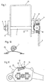
- the clamping and clamping device shown in Fig. 1 has a shaft 1.
- Am an abutment 2 is fixed at one end of the shaft 1, for example via a nut 3, which is screwed onto the end thread of this shaft 1 and is secured here.
- a second abutment is spaced from this abutment 2 5 provided, which is penetrated by the shaft 1, with a small Game, so that the shaft 1 is rotatable relative to this abutment 5.
- This abutment 5 acts an actuator 6 with an operating lever 7 together, this actuator 6 in the embodiment shown is non-rotatably connected to the shaft 1.
- This actuator 6 has in the adjacent second abutment 5th facing surface 8 two wells lying symmetrically with respect to the shaft 1 9, in which there are freely rotatably mounted cylindrical rolling elements 10 which are designed here as cylindrical rollers, this arrangement being designed in this way is that these rolling elements 10 protrude slightly from the surface 8.
- the axes of the the two rollers 10 are in alignment and intersect the axis of the shaft 1.
- On a laterally projecting section 11 of the actuator 6 is a Gear 12 fixedly mounted, the part of a hydraulic damping or Braking device 13 is.
- This actuator 6 also has two edges bump-like stops 14. In the peripheral region of the actuator 6 and here between the two stops 14 is a leaf spring 15 with one Set in late 16. This leaf spring 15 has a parallel to the axis of the shaft 1 extending and directed against the axis, wedge-like deformation 17.
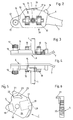
- FIG. 7 shows the relative position of the spring 15 and the cam 22 to one another, when the tensioning and clamping device is unclamped when it is released.
- the Spring 15 is somewhat distanced from cam 22 when the catch is released. It but it is also possible to design this arrangement so that even when solved If the spring 15 latches against the cam 22 under pretension, which schematically illustrates Fig. 11. Due to the relative rotation of the spring 15 and cam 22, the spring 15 is deflected radially and thereby tensioned.
- the spring 15 can rest on the cam 22 over the entire length thereof or only over a small part of the length of the cam. Depending on the constructive In this way, the balance of forces during pivoting is configured the parts affected against each other.
- This gear 12 is one hydraulic damping or braking device 13 in operative connection, so that the actuator 6 by means of the operating lever 7 against an always uniform acting force is pivotable.
- the spring 15 lies on the axis of the Shaft 1 seen from outside the cam 22. It is within the scope of the invention place the spring inwards so that it is off the axis of the shaft 1 seen from a smaller radial distance than the cam 22. Der The cam is then to be shaped according to its described function.
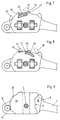
- the rolling elements are mounted in the actuator 6, so it is possible to accommodate them in the abutment 5 and then the Arrange runways for these rolling elements in the actuator 6.
- leaf spring 15 can also act in the radial direction spring can be provided, possibly via an intermediate link (ball) as Snap part is formed.
- the helix-like runways can be somewhat tortuous, so that the points of contact between the rolling element and the runway at the relative Swiveling of actuator 6 and abutment 5 to each other on one Spiral lie, the axis of which forms the shaft 1.
- This twist of the runway is designed so that the rolling element in the clamping or clamping position at the end of their rolling path as close as possible to the shaft 1 and at Loosen the clamping and clamping device in one of the mentioned axes take a distant position. The extent of this twist is very small and in not shown in the drawing.
Landscapes
- Engineering & Computer Science (AREA)
- Chemical & Material Sciences (AREA)
- Combustion & Propulsion (AREA)
- Transportation (AREA)
- Mechanical Engineering (AREA)
- Clamps And Clips (AREA)
- Transmission Devices (AREA)
- Braking Arrangements (AREA)
Applications Claiming Priority (2)
| Application Number | Priority Date | Filing Date | Title |
|---|---|---|---|
| DE19718031 | 1997-04-29 | ||
| DE19718031A DE19718031C1 (de) | 1997-04-29 | 1997-04-29 | Spann- und Klemmvorrichtung |
Publications (3)
| Publication Number | Publication Date |
|---|---|
| EP0875439A2 true EP0875439A2 (fr) | 1998-11-04 |
| EP0875439A3 EP0875439A3 (fr) | 1999-11-03 |
| EP0875439B1 EP0875439B1 (fr) | 2001-05-02 |
Family
ID=7828068
Family Applications (1)
| Application Number | Title | Priority Date | Filing Date |
|---|---|---|---|
| EP98104211A Expired - Lifetime EP0875439B1 (fr) | 1997-04-29 | 1998-03-10 | Dispositif de tension et de serrage |
Country Status (10)
| Country | Link |
|---|---|
| US (1) | US6089780A (fr) |
| EP (1) | EP0875439B1 (fr) |
| JP (1) | JP4294756B2 (fr) |
| CN (1) | CN1089702C (fr) |
| AR (1) | AR011471A1 (fr) |
| BR (1) | BR9801977A (fr) |
| CA (1) | CA2231966C (fr) |
| DE (2) | DE19718031C1 (fr) |
| ES (1) | ES2158629T3 (fr) |
| ZA (1) | ZA982637B (fr) |
Families Citing this family (9)
| Publication number | Priority date | Publication date | Assignee | Title |
|---|---|---|---|---|
| DE10261538A1 (de) * | 2002-12-23 | 2004-07-01 | Thyssenkrupp Presta Ag | Lenksäule |
| GB2428771B (en) * | 2005-07-30 | 2009-05-13 | Nsk Steering Sys Europ Ltd | Detent device and vehicle steering column incorporating same |
| DE102011055410A1 (de) * | 2011-11-16 | 2013-05-16 | Thyssenkrupp Presta Aktiengesellschaft | Feststelleinrichtung für eine verstellbare Lenksäule für ein Kraftfahrzeug |
| DE102011057104B4 (de) | 2011-12-28 | 2016-03-10 | Thyssenkrupp Presta Aktiengesellschaft | Feststelleinrichtung für eine verstellbare Lenksäule |
| DE102012100486B3 (de) | 2012-01-20 | 2013-02-28 | Thyssenkrupp Presta Aktiengesellschaft | Lenksäule für ein Kraftfahrzeug |
| DE102012102556B3 (de) | 2012-03-26 | 2013-06-27 | Thyssenkrupp Presta Aktiengesellschaft | Aufsteckkörper für einen Spannbolzen |
| DE102014018653B4 (de) | 2014-12-13 | 2020-06-18 | Torsten Harms | Klemmeinrichtung für eine Lenksäule eines Kraftfahrzeugs |
| CN104763729B (zh) * | 2015-04-15 | 2017-05-10 | 中国电子科技集团公司第二十二研究所 | 一种自锁式固紧器 |
| CN104959927B (zh) * | 2015-06-12 | 2016-11-02 | 雄华机械(苏州)有限公司 | 一种汽车方向盘位置调节装置的固定治具 |
Citations (2)
| Publication number | Priority date | Publication date | Assignee | Title |
|---|---|---|---|---|
| EP0493181B1 (fr) | 1990-12-28 | 1994-03-30 | Ecia - Equipements Et Composants Pour L'industrie Automobile | Dispositif de blocage en position d'une colonne de direction réglable de véhicule automobile |
| EP0600700B1 (fr) | 1992-12-02 | 1995-09-13 | The Torrington Company Limited | Mécanisme de serrage pour une colonne de direction |
Family Cites Families (14)
| Publication number | Priority date | Publication date | Assignee | Title |
|---|---|---|---|---|
| US3665778A (en) * | 1970-09-02 | 1972-05-30 | Ford Motor Co | Energy absorbing steering column |
| DE2944648A1 (de) * | 1979-11-06 | 1981-05-14 | Skf Kugellagerfabriken Gmbh, 8720 Schweinfurt | Vorrichtung zum befestigen einer achse o.dgl. in einer nabe und anwendung derselben |
| DE3602247C2 (de) * | 1986-01-25 | 1997-01-23 | Widia Gmbh | Werkzeugkupplung zur Verbindung eines wechselbaren Werkzeugkopfes mit einem Werkzeughalter an einer Werkzeugmaschine |
| NL8601035A (nl) * | 1986-04-23 | 1987-11-16 | Volvo Car Bv | Stuurkolomklem. |
| US4911574A (en) * | 1986-12-23 | 1990-03-27 | Tri Tool Inc. | Cam lock for tool elements |
| FR2654058B1 (fr) * | 1989-11-09 | 1992-02-21 | Ecia Equip Composants Ind Auto | Dispositif de maintien d'un organe tubulaire en particulier d'une colonne de direction de vehicule automobile. |
| JPH085398Y2 (ja) * | 1991-04-26 | 1996-02-14 | 株式会社日研工作所 | 回動軸部のクランプ装置 |
| SE502558C2 (sv) * | 1994-03-09 | 1995-11-13 | Fuji Autotech Ab | Teleskoperbart och svängbart rattstångsfäste |
| DE19506210C1 (de) * | 1995-02-23 | 1996-06-27 | Lemfoerder Metallwaren Ag | Klemmvorrichtung für eine einstellbare Lenksäule in Kraftfahrzeugen |
| US5606892A (en) * | 1995-03-31 | 1997-03-04 | Ford Motor Company | Modular steering column assembly |
| US5785461A (en) * | 1996-01-18 | 1998-07-28 | Lambert; Gene F. | Wedge tensioning device |
| FR2745777B1 (fr) * | 1996-03-06 | 1998-04-30 | Lemforder Nacam Sa | Dispositif antirotation de corps de colonne de direction de vehicule automobile |
| DE19640196C1 (de) * | 1996-09-30 | 1998-04-23 | Schaeffler Waelzlager Ohg | Klemmvorrichtung für eine Lenksäule |
| US5787759A (en) * | 1997-02-11 | 1998-08-04 | General Motors Corporation | Position control apparatus for steering column |
-
1997
- 1997-04-29 DE DE19718031A patent/DE19718031C1/de not_active Expired - Fee Related
-
1998
- 1998-03-10 ES ES98104211T patent/ES2158629T3/es not_active Expired - Lifetime
- 1998-03-10 DE DE59800659T patent/DE59800659D1/de not_active Expired - Lifetime
- 1998-03-10 EP EP98104211A patent/EP0875439B1/fr not_active Expired - Lifetime
- 1998-03-30 ZA ZA982637A patent/ZA982637B/xx unknown
- 1998-04-22 CA CA002231966A patent/CA2231966C/fr not_active Expired - Fee Related
- 1998-04-24 CN CN98107447A patent/CN1089702C/zh not_active Expired - Lifetime
- 1998-04-27 US US09/067,501 patent/US6089780A/en not_active Expired - Lifetime
- 1998-04-27 JP JP11729898A patent/JP4294756B2/ja not_active Expired - Fee Related
- 1998-04-29 AR ARP980101979A patent/AR011471A1/es unknown
- 1998-04-29 BR BR9801977A patent/BR9801977A/pt not_active IP Right Cessation
Patent Citations (2)
| Publication number | Priority date | Publication date | Assignee | Title |
|---|---|---|---|---|
| EP0493181B1 (fr) | 1990-12-28 | 1994-03-30 | Ecia - Equipements Et Composants Pour L'industrie Automobile | Dispositif de blocage en position d'une colonne de direction réglable de véhicule automobile |
| EP0600700B1 (fr) | 1992-12-02 | 1995-09-13 | The Torrington Company Limited | Mécanisme de serrage pour une colonne de direction |
Also Published As
| Publication number | Publication date |
|---|---|
| CA2231966C (fr) | 2006-07-11 |
| US6089780A (en) | 2000-07-18 |
| CA2231966A1 (fr) | 1998-10-29 |
| EP0875439A3 (fr) | 1999-11-03 |
| EP0875439B1 (fr) | 2001-05-02 |
| JPH10328950A (ja) | 1998-12-15 |
| AR011471A1 (es) | 2000-08-16 |
| DE59800659D1 (de) | 2001-06-07 |
| ZA982637B (en) | 1998-10-08 |
| BR9801977A (pt) | 1999-06-15 |
| DE19718031C1 (de) | 1998-08-13 |
| JP4294756B2 (ja) | 2009-07-15 |
| CN1198373A (zh) | 1998-11-11 |
| ES2158629T3 (es) | 2001-09-01 |
| CN1089702C (zh) | 2002-08-28 |
Similar Documents
| Publication | Publication Date | Title |
|---|---|---|
| DE3000926C2 (de) | Stativarm für Meßgeräte, insbesondere optische Geräte, wie Kameras oder dergleichen | |
| EP0239830B1 (fr) | Dispositif de réglage de la position angulaire relative entre une roue dentée et une couronne dentée coaxiale | |
| DE3104707C2 (de) | Einstellvorrichtung für eine in axialer Richtung verstell- und einstellbare Lenksäule für Kraftfahrzeuge | |
| DE3222758A1 (de) | Stellvorrichtung fuer sitze, insbesondere kraftfahrzeugsitze | |
| EP3708753B1 (fr) | Ferrure de couvercle destinée à la fixation pivotante d'un couvercle de meuble sur un corps de meuble | |
| DE3304454C2 (fr) | ||
| EP0875439B1 (fr) | Dispositif de tension et de serrage | |
| EP1332306B1 (fr) | Dispositif de reglage a rotation | |
| DE3403297C2 (fr) | ||
| DE2838234B2 (de) | Gleichlauf-Drehgelenk in Tripod-Bauart zwischen zwei Wellenenden | |
| DE3012765C2 (fr) | ||
| DE19922333A1 (de) | Scheibenbremse mit Feststellbremsfunktion | |
| EP1382509A1 (fr) | Colonne de direction | |
| DE3335196C1 (de) | Spannvorrichtung für verzahnte Werkstücke | |
| EP0525507B1 (fr) | Dispositif de réglage d'un actionneur pour régler la cylindrée d'une machine hydrostatique | |
| AT523901B1 (de) | Selbstsichernder Vorspannring für Federbeine | |
| EP3747393B1 (fr) | Vis d'extension orthodontique | |
| DE3146289A1 (de) | Bremsfederkupplung fuer stellgetriebe, insbesondere von sitzstellvorrichtungen | |
| DE10234371B4 (de) | Blockierbare Feststellvorrichtung | |
| DE455844C (de) | Lenkvorrichtung fuer Kraftfahrzeuge | |
| DE10002263B4 (de) | Spannvorrichtung zum axialen Festspannen eines insbesondere scheibenförmigen Werkzeugs an der Spindel eines Elektrowerkzeugs | |
| DE2220166C2 (de) | Spannmutter | |
| EP1598213B1 (fr) | Compas blocable avec dispositif d'adjustement rapide | |
| DE102018128252A1 (de) | Spannbolzen zum lösbaren Verbinden von Bauteilen | |
| DE102021127470B3 (de) | Anordnung zum Einstellen eines Drehmoments |
Legal Events
| Date | Code | Title | Description |
|---|---|---|---|
| PUAI | Public reference made under article 153(3) epc to a published international application that has entered the european phase |
Free format text: ORIGINAL CODE: 0009012 |
|
| AK | Designated contracting states |
Kind code of ref document: A2 Designated state(s): DE ES FR GB IT NL SE |
|
| AX | Request for extension of the european patent |
Free format text: AL;LT;LV;MK;RO;SI |
|
| PUAL | Search report despatched |
Free format text: ORIGINAL CODE: 0009013 |
|
| AK | Designated contracting states |
Kind code of ref document: A3 Designated state(s): AT BE CH DE DK ES FI FR GB GR IE IT LI LU MC NL PT SE |
|
| AX | Request for extension of the european patent |
Free format text: AL;LT;LV;MK;RO;SI |
|
| GBC | Gb: translation of claims filed (gb section 78(7)/1977) | ||
| 17P | Request for examination filed |
Effective date: 20000216 |
|
| AKX | Designation fees paid |
Free format text: DE ES FR GB IT NL SE |
|
| GRAG | Despatch of communication of intention to grant |
Free format text: ORIGINAL CODE: EPIDOS AGRA |
|
| GRAG | Despatch of communication of intention to grant |
Free format text: ORIGINAL CODE: EPIDOS AGRA |
|
| GRAH | Despatch of communication of intention to grant a patent |
Free format text: ORIGINAL CODE: EPIDOS IGRA |
|
| 17Q | First examination report despatched |
Effective date: 20000929 |
|
| GRAH | Despatch of communication of intention to grant a patent |
Free format text: ORIGINAL CODE: EPIDOS IGRA |
|
| GRAA | (expected) grant |
Free format text: ORIGINAL CODE: 0009210 |
|
| AK | Designated contracting states |
Kind code of ref document: B1 Designated state(s): DE ES FR GB IT NL SE |
|
| PG25 | Lapsed in a contracting state [announced via postgrant information from national office to epo] |
Ref country code: NL Free format text: LAPSE BECAUSE OF FAILURE TO SUBMIT A TRANSLATION OF THE DESCRIPTION OR TO PAY THE FEE WITHIN THE PRESCRIBED TIME-LIMIT Effective date: 20010502 |
|
| REF | Corresponds to: |
Ref document number: 59800659 Country of ref document: DE Date of ref document: 20010607 |
|
| ITF | It: translation for a ep patent filed |
Owner name: INTERPATENT ST.TECN. BREV. |
|
| ET | Fr: translation filed | ||
| PG25 | Lapsed in a contracting state [announced via postgrant information from national office to epo] |
Ref country code: SE Free format text: LAPSE BECAUSE OF FAILURE TO SUBMIT A TRANSLATION OF THE DESCRIPTION OR TO PAY THE FEE WITHIN THE PRESCRIBED TIME-LIMIT Effective date: 20010802 |
|
| GBT | Gb: translation of ep patent filed (gb section 77(6)(a)/1977) |
Effective date: 20010724 |
|
| REG | Reference to a national code |
Ref country code: ES Ref legal event code: FG2A Ref document number: 2158629 Country of ref document: ES Kind code of ref document: T3 |
|
| NLV1 | Nl: lapsed or annulled due to failure to fulfill the requirements of art. 29p and 29m of the patents act | ||
| REG | Reference to a national code |
Ref country code: GB Ref legal event code: IF02 |
|
| PLBE | No opposition filed within time limit |
Free format text: ORIGINAL CODE: 0009261 |
|
| STAA | Information on the status of an ep patent application or granted ep patent |
Free format text: STATUS: NO OPPOSITION FILED WITHIN TIME LIMIT |
|
| 26N | No opposition filed | ||
| PG25 | Lapsed in a contracting state [announced via postgrant information from national office to epo] |
Ref country code: IT Free format text: LAPSE BECAUSE OF NON-PAYMENT OF DUE FEES Effective date: 20100310 |
|
| PGRI | Patent reinstated in contracting state [announced from national office to epo] |
Ref country code: IT Effective date: 20110616 |
|
| PG25 | Lapsed in a contracting state [announced via postgrant information from national office to epo] |
Ref country code: DE Free format text: LAPSE BECAUSE OF NON-PAYMENT OF DUE FEES Effective date: 20111001 |
|
| REG | Reference to a national code |
Ref country code: FR Ref legal event code: PLFP Year of fee payment: 19 |
|
| PGFP | Annual fee paid to national office [announced via postgrant information from national office to epo] |
Ref country code: GB Payment date: 20160331 Year of fee payment: 19 Ref country code: FR Payment date: 20160330 Year of fee payment: 19 |
|
| PGFP | Annual fee paid to national office [announced via postgrant information from national office to epo] |
Ref country code: DE Payment date: 20160525 Year of fee payment: 19 Ref country code: ES Payment date: 20160422 Year of fee payment: 19 |
|
| PG25 | Lapsed in a contracting state [announced via postgrant information from national office to epo] |
Ref country code: IT Free format text: LAPSE BECAUSE OF NON-PAYMENT OF DUE FEES Effective date: 20160310 |
|
| PG25 | Lapsed in a contracting state [announced via postgrant information from national office to epo] |
Ref country code: IT Free format text: LAPSE BECAUSE OF NON-PAYMENT OF DUE FEES Effective date: 20160310 |
|
| PGFP | Annual fee paid to national office [announced via postgrant information from national office to epo] |
Ref country code: IT Payment date: 20160325 Year of fee payment: 19 |
|
| PGRI | Patent reinstated in contracting state [announced from national office to epo] |
Ref country code: IT Effective date: 20170710 |
|
| REG | Reference to a national code |
Ref country code: DE Ref legal event code: R119 Ref document number: 59800659 Country of ref document: DE |
|
| GBPC | Gb: european patent ceased through non-payment of renewal fee |
Effective date: 20170310 |
|
| REG | Reference to a national code |
Ref country code: FR Ref legal event code: ST Effective date: 20171130 |
|
| PG25 | Lapsed in a contracting state [announced via postgrant information from national office to epo] |
Ref country code: FR Free format text: LAPSE BECAUSE OF NON-PAYMENT OF DUE FEES Effective date: 20170331 |
|
| PG25 | Lapsed in a contracting state [announced via postgrant information from national office to epo] |
Ref country code: IT Free format text: LAPSE BECAUSE OF NON-PAYMENT OF DUE FEES Effective date: 20170310 Ref country code: GB Free format text: LAPSE BECAUSE OF NON-PAYMENT OF DUE FEES Effective date: 20170310 |
|
| PGRI | Patent reinstated in contracting state [announced from national office to epo] |
Ref country code: IT Effective date: 20170710 |
|
| REG | Reference to a national code |
Ref country code: ES Ref legal event code: FD2A Effective date: 20180507 |
|
| PG25 | Lapsed in a contracting state [announced via postgrant information from national office to epo] |
Ref country code: ES Free format text: LAPSE BECAUSE OF NON-PAYMENT OF DUE FEES Effective date: 20170311 |
|
| RIC2 | Information provided on ipc code assigned after grant |
Ipc: B62D 1/18 20060101AFI19980804BHEP |
|
| PG25 | Lapsed in a contracting state [announced via postgrant information from national office to epo] |
Ref country code: DE Free format text: LAPSE BECAUSE OF NON-PAYMENT OF DUE FEES Effective date: 20171003 |