EP0875403A2 - Luftreifen - Google Patents
Luftreifen Download PDFInfo
- Publication number
- EP0875403A2 EP0875403A2 EP98303337A EP98303337A EP0875403A2 EP 0875403 A2 EP0875403 A2 EP 0875403A2 EP 98303337 A EP98303337 A EP 98303337A EP 98303337 A EP98303337 A EP 98303337A EP 0875403 A2 EP0875403 A2 EP 0875403A2
- Authority
- EP
- European Patent Office
- Prior art keywords
- block
- shaped land
- tire
- shaped
- rib
- Prior art date
- Legal status (The legal status is an assumption and is not a legal conclusion. Google has not performed a legal analysis and makes no representation as to the accuracy of the status listed.)
- Granted
Links
Images

Classifications
-
- B—PERFORMING OPERATIONS; TRANSPORTING
- B60—VEHICLES IN GENERAL
- B60C—VEHICLE TYRES; TYRE INFLATION; TYRE CHANGING; CONNECTING VALVES TO INFLATABLE ELASTIC BODIES IN GENERAL; DEVICES OR ARRANGEMENTS RELATED TO TYRES
- B60C11/00—Tyre tread bands; Tread patterns; Anti-skid inserts
- B60C11/03—Tread patterns
- B60C11/13—Tread patterns characterised by the groove cross-section, e.g. for buttressing or preventing stone-trapping
- B60C11/1376—Three dimensional block surfaces departing from the enveloping tread contour
- B60C11/1384—Three dimensional block surfaces departing from the enveloping tread contour with chamfered block corners
-
- B—PERFORMING OPERATIONS; TRANSPORTING
- B60—VEHICLES IN GENERAL
- B60C—VEHICLE TYRES; TYRE INFLATION; TYRE CHANGING; CONNECTING VALVES TO INFLATABLE ELASTIC BODIES IN GENERAL; DEVICES OR ARRANGEMENTS RELATED TO TYRES
- B60C11/00—Tyre tread bands; Tread patterns; Anti-skid inserts
- B60C11/03—Tread patterns
- B60C11/0306—Patterns comprising block rows or discontinuous ribs
- B60C11/0309—Patterns comprising block rows or discontinuous ribs further characterised by the groove cross-section
-
- B—PERFORMING OPERATIONS; TRANSPORTING
- B60—VEHICLES IN GENERAL
- B60C—VEHICLE TYRES; TYRE INFLATION; TYRE CHANGING; CONNECTING VALVES TO INFLATABLE ELASTIC BODIES IN GENERAL; DEVICES OR ARRANGEMENTS RELATED TO TYRES
- B60C11/00—Tyre tread bands; Tread patterns; Anti-skid inserts
- B60C11/03—Tread patterns
- B60C11/11—Tread patterns in which the raised area of the pattern consists only of isolated elements, e.g. blocks
-
- B—PERFORMING OPERATIONS; TRANSPORTING
- B60—VEHICLES IN GENERAL
- B60C—VEHICLE TYRES; TYRE INFLATION; TYRE CHANGING; CONNECTING VALVES TO INFLATABLE ELASTIC BODIES IN GENERAL; DEVICES OR ARRANGEMENTS RELATED TO TYRES
- B60C11/00—Tyre tread bands; Tread patterns; Anti-skid inserts
- B60C11/03—Tread patterns
- B60C11/13—Tread patterns characterised by the groove cross-section, e.g. for buttressing or preventing stone-trapping
- B60C11/1376—Three dimensional block surfaces departing from the enveloping tread contour
- B60C11/1392—Three dimensional block surfaces departing from the enveloping tread contour with chamfered block edges
-
- Y—GENERAL TAGGING OF NEW TECHNOLOGICAL DEVELOPMENTS; GENERAL TAGGING OF CROSS-SECTIONAL TECHNOLOGIES SPANNING OVER SEVERAL SECTIONS OF THE IPC; TECHNICAL SUBJECTS COVERED BY FORMER USPC CROSS-REFERENCE ART COLLECTIONS [XRACs] AND DIGESTS
- Y10—TECHNICAL SUBJECTS COVERED BY FORMER USPC
- Y10S—TECHNICAL SUBJECTS COVERED BY FORMER USPC CROSS-REFERENCE ART COLLECTIONS [XRACs] AND DIGESTS
- Y10S152/00—Resilient tires and wheels
- Y10S152/90—Tread pattern having no blocks and having circumferential ribs defined by zig-zag circumferential grooves
-
- Y—GENERAL TAGGING OF NEW TECHNOLOGICAL DEVELOPMENTS; GENERAL TAGGING OF CROSS-SECTIONAL TECHNOLOGIES SPANNING OVER SEVERAL SECTIONS OF THE IPC; TECHNICAL SUBJECTS COVERED BY FORMER USPC CROSS-REFERENCE ART COLLECTIONS [XRACs] AND DIGESTS
- Y10—TECHNICAL SUBJECTS COVERED BY FORMER USPC
- Y10S—TECHNICAL SUBJECTS COVERED BY FORMER USPC CROSS-REFERENCE ART COLLECTIONS [XRACs] AND DIGESTS
- Y10S152/00—Resilient tires and wheels
- Y10S152/902—Non-directional tread pattern having no circumferential rib and having blocks defined by circumferential grooves and transverse grooves
Definitions
- This invention relates to a pneumatic tire having excellent all-over running performances such as traction and braking performances, cornering property and straight running stability and the like without sacrificing the other tire properties.
- the gripping force of the tire against the road surface corresponds to friction force between the ground contact region of the tire and the road surface, so that the enhancement of the friction force makes the enhancement of the gripping force and hence improves the above running performances.
- a tread portion As means for enhancing the friction force, it is useful to conduct the improvement of a tread portion, concretely the improvement of a distribution of grooves (for example, circumferential grooves, lateral grooves, etc.) arranged in the tread portion, a shape of each groove, a shape of a land portion and the like.
- grooves for example, circumferential grooves, lateral grooves, etc.
- the improvement of the tread portion (particularly, a tread pattern) has a large influence on drainage property, noise level, ride comfortability against vibrations, wear resistance and the like, so that it is most difficult to improve the running performance by the conventionally practiced improvement of the tread portion while maintaining the above properties.
- the inventor has made detailed investigations with respect to a state of contacting the tread portion with the road surface (concretely, a distribution of ground contact pressure) by using the conventional tire having a usual block pattern in order to improve the friction force between the ground contact region of the tire and the road surface.
- the inventor has thought that the friction force generated between the ground contact region of the tire and the road surface can effectively be enhanced by mitigating the concentration of the ground contact pressure in the edge portion of the block-shaped land to uniformize the ground contact pressure in each of the block-shaped lands.
- chamfer the edge portion of the block-shaped land as means for uniformizing the ground contact pressure in the block-shaped land.
- a tire wherein a curved or flat chamfered portion is formed in only edge portions of the block-shaped land corresponding to stepping-in side and kicking-out side of the tire (JP-A-64-22601 etc.) and a tire wherein all edge portions of the block-shaped land is chamfered at a uniform inclination angle over a full periphery thereof (JP-A-2-179508).
- the former tire has an effect of mitigating the ground contact pressure in the edge portions of the block-shaped land corresponding to the stepping-in side and kicking-out side of the tire, but when the lateral force and the like are applied to the tire, it can not sufficiently be mitigated to concentrate the ground contact pressure in an edge portion of the block-shaped land facing a circumferential main groove.
- the inventor has made further studies with respect to the distribution of the ground contact pressure on the edge portions of the block-shaped land for effectively enhancing the friction force and found that the ground contact pressure in the edge portion is proportional to a distance from a given position of the block-shaped land.
- the invention has been accomplished under a technical idea that when the edge portion of the block-shaped land is subjected to a chamfering at a curvature in accordance with the distance from the given position of the block-shaped land, the ground contact pressure in the block-shaped land can be uniformized to effectively enhance the friction force without so decreasing the ground contact area.
- an object of the invention to provide a pneumatic tire having excellent running performances such as braking performance, cornering property, straight running stability and the like without sacrificing the other tire properties by subjecting edge portions of divided lands to chamfering at a curvature in accordance with a distance from a given position of the land.
- a pneumatic tire comprising a tread portion having a plurality of block-shaped lands defined by a plurality of tread grooves formed in the tread portion, an improvement wherein each edge portion of the same block-shaped land located at a boundary between a ground contact region and a side wall of the block-shaped land is subjected to chamfering convexly outward in a radial direction of the tire at a curvature varied in accordance with a distance from a center position of the block-shaped land.
- tread groove means all grooves arranged in the tread portion and includes, for example, circumferential main grooves extending along the circumference of the tire, auxiliary grooves extending across the circumferential main grooves and the like.
- the chamfering is carried out so as to increase or decrease a radius of curvature in the edge portion of the same block-shaped land in accordance with the distance from the center position of the block-shaped land, and that in case of the block-shaped lands located at different tread regions, the radius of chamfering curvature in the edge portion of the block-shaped land located at each side region of the tread is made larger than that in the edge portion of the block-shaped land located at the central region thereof.
- a pneumatic tire comprising a tread portion having a plurality of rib-shaped lands defined between at least two circumferential main grooves extending zigzag along the circumference of the tire and/or between the circumferential main groove and a tread end, an improvement wherein each edge portion of the same rib-shaped land located at a boundary between a ground contact region and a side wall of the rib-shaped land is subjected to chamfering convexly outward in a radial direction of the tire at a curvature varied in accordance with a distance vertically drawn from a circumference position of the tire equally dividing the rib-shaped land.
- the chamfering is carried out so as to increase or decrease a radius of curvature in the edge portion of the same rib-shaped land in accordance with the distance vertically drawn from the circumference position of the tire, and that in case of the rib-shaped lands located at different tread regions, the radius of chamfering curvature in the edge portion of the rib-shaped land located at each side region of the tread is made larger than that in the edge portion of the rib-shaped land located at the central region thereof.
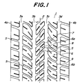
- Fig. 1 is diagrammatically shown a typical tread pattern of the pneumatic tire according to the first aspect of the invention, in which numeral 1 is a tread portion, numeral 2 a circumference of the tire, numeral 3a-3d circumferential main grooves, numeral 4a and 4b tread ends in the widthwise direction of the tire, numeral 5 an auxiliary groove, numeral 6 a block-shaped land, and numeral 9 an edge portion of the block-shaped land.
- the tread portion 1 is divided into a plurality of block-shaped lands 6 to form a block pattern by arranging in the tread portion 1 at least two circumferential main grooves 3a-3d (four grooves in the illustrated embodiment) each extending along the circumference 2 of the tire, and a plurality of auxiliary grooves 5 between these circumferential main grooves 3a-3b, 3b-3c and 3c-3d and/or between the circumferential main groove 3a or 3d and the tread end 4a or 4b and communicating with these circumferential main grooves.
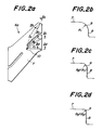
- FIG. 2a is enlargedly shown one block-shaped land 6a pulled out from the block-shaped lands constituting the tread portion shown in Fig. 1, and sections of lines IIb-IIb, IIc-IIc and IId-IId in Fig. 2a are shown in Figs. 2b-2d, respectively.
- a main feature in the construction of the invention lies in that each edge portion 9 of the same block-shaped land 6a located at a boundary between a ground contact region 7 and a side wall 8 of the block-shaped land is subjected to chamfering convexly outward in a radial direction of the tire at a curvature varied in accordance with a distance from a center position 10 of the block-shaped land 6.
- the concentration of the ground contact pressure in the edge portion of the block-shaped land is considered to mainly depend on the following two reasons.
- a first reason is a case of causing the above concentration when a load (in a vertical direction) is applied to the block-shaped land.
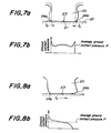
- the block-shaped land 20 having a shape shown by dotted lines tends to be spread in a ground contact region 21 by collapse deformation shown by a solid line under compression, but can not spread owing to the contact with a road surface 22 and hence shear strain fc is generated between the block-shaped land 20 and the road surface 22.
- This strain fc accumulates from a center position 23 of the block-shaped land 20 toward both edge portions 24a, 24b thereof and becomes maximum at both edge portions 24a, 24b.
- shear force applied to the block-shaped land 20 receives through the shear strain fc acts in a direction of standing up the edge portions 24a, 24b toward the center position 23 of the block-shaped land 20, and hence the ground contact pressure may concentrate in the edge portions 24a, 24b(as shown in Fig. 7b).
- a second reason is a case of causing the above concentration when the longitudinal force, the lateral force or the like is applied to the block-shaped land 20.
- the bending deformation or shearing deformation of the block-shaped land 20 is caused by friction force fs (shear force) applied to the block-shaped land 20, and hence there is obtained a distribution of ground contact pressure that the ground contact pressure becomes high at the edge portion 24a corresponding to an input side of the friction force fs (as shown in Fig. 8b).
- the friction force fs acts in a direction of standing up the edge portion 24a at the input side, whereby the ground contact pressure is further concentrated in the edge portion.
- the block-shaped land in the ground contact region has various shapes ranging from a simple rectangular shape to a complicated shape.
- the inventor has made studies with respect to the concentration of ground contact pressure in the edge portion of the block-shaped land in tires having various shapes in the block-shaped land and found that the ground contact pressure at the edge portion of the block-shaped land is proportional to a distance from a center position of the block-shaped land irrespectively of the shape of the block-shaped land.
- each edge portion 9 of the same block-shaped land 6a located at a boundary between the ground contact region 7 and the side wall 8 of the block-shaped land is subjected to chamfering convexly outward in a radial direction of the tire at a curvature varied in accordance with a distance from the center position 10 of the block-shaped land 6.
- the friction force between the ground contact region of the tire and the road surface can effectively be enhanced to improve the running performances.
- there is caused no degradation of the other properties such as the drainage property and the like.
- radii of curvature in the chamfering R 1 , R 2 , R 3 are increased or decreased in correspondence with distances from the center position 10 of the block-shaped land 6 as shown in Figs. 2a-2d.
- the edge portions 9 of the block-shaped land 6 are subjected to chamfering in such a manner that the radius R1 at corners 11a, 11b most apart from the center position 10 of the block-shaped land 6 (distance: l 1 ) is maximum and the radius of curvature in the edge portion of the block-shaped land 6 gradually decreases from the corners 11a, 11b toward positions 12a, 12b nearest to the center position 10 (distance: I m+n ) and the radius of curvature R m+n at the positions 12a, 12b is minimum.
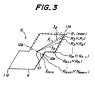
- Fig. 3 are shown curvatures of the edge portions in only an upper half-part of the block-shaped land for the convenience of the explanation.
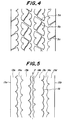
- Fig. 5 is shown a typical tread pattern of the pneumatic tire according to the second aspect of the invention.
- the tread portion comprises at least two circumferential main grooves 14a-14c (three main grooves in the illustrated embodiment) extending zigzag along the circumference 2 of the tire and rib-shaped lands 13a-13d defined between these main grooves and between the main groove 14a or 14c and the tread end 15a or 15b.
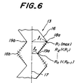
- Fig. 6 is shown a part of a typical zigzag rib-shaped land 13.
- Fig. 6 it has been found that the same effect as in the first aspect of the invention is obtained by subjecting each edge portion 16 of the same rib-shaped land 13 located at a boundary between a ground contact region and a side wall of the rib-shaped land to chamfering convexly outward in a radial direction of the tire at a curvature varied in accordance with a distance vertically drawn from a circumference position 17 of the tire equally dividing the rib-shaped land.
- each edge portion 16 of the same rib-shaped land 13 located at a boundary between a ground contact region and a side wall of the rib-shaped land is subjected to chamfering convexly outward in a radial direction of the tire at a curvature varied in accordance with a distance vertically drawn from a circumference position 17 of the tire equally dividing the rib-shaped land.
- the friction force between the ground contact region of the tire and the road surface can effectively be enhanced to improve the running performances.
- there is caused no degradation of the other properties such as the drainage property and the like.
- the edge portion 19 of the rib-shaped land 13 is subjected to chamfering in such a manner that the radius of curvature R 1 in corners 18a, 18b most apart from the vertical distance from the circumference position 17 of the tire (distance: l 1 ) is maximum and the radius of curvature in the edge portions of the rib-shaped land 13 gradually decreases from the corners 18a, 18b toward corners 19a, 19b nearest to the vertical distance from the circumference position 17 (distance: l n ) and the radius of curvature R n in the corners 19a, 19b is minimum.
- the radius of chamfering curvature in the edge portion of the rib-shaped land 13a, 13d located at each side region of the tread is made larger than the radius of chamfering curvature in the edge portion of the rib-shaped lands 13b, 13c located at the central region thereof.
- the tire may have such a use embodiment that the tread portion indicates a block pattern defined by circumferential main zigzag grooves 14a-14c and auxiliary grooves 5a-5c having a shallow groove depth as shown in Fig. 4 at an initial worn stage of the tire but changes into a rib pattern having no auxiliary grooves 5a-5c as shown in Fig. 5 on and after middle worn stage of the tire.
- the edge portion of the land is subjected to chamfering at a convex curvature in the invention, if it is intended to further decrease the ground contact pressure, sipes may be disposed in the edge portion.
- a tire of this example is a pneumatic radial tire for passenger car having a tread pattern as shown in Fig. 1 and a tire size of 195/65R14, in which an edge portion of a block-shaped land is subjected to chamfering in such a manner that a radius of curvature at the chamfering is 2.5 mm at a position corresponding to a maximum distance from the center position 10, and 0.5 mm at a position corresponding to a minimum distance from the center position 10, and gently changes within a range of 0.5-2.5 mm at other positions of the edge portion.
- This tire other than the tread pattern is substantially the same as in the usual pneumatic radial tire for passenger car.
- a tire of this example is the same as in Example 1 except that edge portions of block-shaped land 6b other than block-shaped lands 6a located at the central region of the tread are subjected to chamfering in such a manner that a radius of curvature at the chamfering is 3.5 mm at a position corresponding to a maximum distance from the center position 10, and 0.5 mm at a position corresponding to a minimum distance from the center position 10, and gently changes within a range of 0.5-3.5 mm at other positions of the edge portion.
- a tire of this example is a pneumatic radial tire for small-size truck having a tread pattern as shown in Fig. 5 and a tire size of 205/60R17.5, in which an edge portion of a rib-shaped land is subjected to chamfering in such a manner that a radius of curvature at the chamfering is 2.5 mm at a position corresponding to a maximum distance from the circumference position 17, and 1.0 mm at a position corresponding to a minimum distance from the circumference position 17, and gently changes within a range of 1.0-2.5 mm at other positions of the edge portion.
- This tire other than the tread pattern is substantially the same as in the usual pneumatic radial tire for small-size truck.
- a tire of this example is the same as in Example 3 except that edge portions of rib-shaped lands 13a, 13d other than rib-shaped lands 13b, 13c located at the central region of the tread are subjected to chamfering in such a manner that a radius of curvature at the chamfering is 3.5 mm at a position corresponding to a maximum distance from the circumference position 17, and 1.0 mm at a position corresponding to a minimum distance from the circumference position 17, and gently changes within a range of 1.0-3.5 mm at other positions of the edge portion.
- each of the tires in Examples 1-2 and Conventional Examples 1-2 is mounted onto a front-wheel-drive type passenger car having a displacement of 2000 cc (two crewmen ridden on a front seat), while each of the tires in Examples 3-4 and Conventional Examples 3-4 (internal pressure: 6 kgf/cm 2 ) is mounted onto a small-size truck (dual-wheel type as a rear wheel, maximum authorized freight mass: 2t at constant state).
- the tests for evaluating the braking performance, cornering property and straight running stability are carried out by actually running these vehicles.
- the braking performance is evaluated from a value of a running distance measured when the vehicle is run at a speed of 50 km/h on an asphalt road surface of a wet state having no water depth and then rapidly braked to measure a running distance until the stop of the vehicle.
- the cornering property is evaluated from a value of limit lateral gravity measured when the vehicle is run on a cornering test course having a radius of curvature of 50 m.
- the straight running stability is evaluated by a professional driver's feeling when the vehicle is run at a speed of 100 km/h on a flat and dry asphalt road.
- Examples 1 and 2 are excellent in all of the braking performance, the cornering property and the straight running stability as compared with Conventional Examples 1 and 2. Moreover, when the drainage property, noise level, ride comfortability against vibrations and wear resistance are also evaluated with respect to these tires, there is not observed a remarkable difference between Examples 1, 2 and Conventional Examples 1, 2.
- Examples 3 and 4 are excellent in all of the braking performance and the straight running stability as compared with Conventional Examples 3 and 4. Moreover, when the drainage property, noise level, ride comfortability against vibrations and wear resistance are also evaluated with respect to these tires, there is not observed a remarkable difference between Examples 3, 4 and Conventional Examples 3, 4.
- the considerable effects can particularly be expected to develop at an initial use stage of the tire.
Landscapes
- Engineering & Computer Science (AREA)
- Mechanical Engineering (AREA)
- Tires In General (AREA)
Applications Claiming Priority (3)
| Application Number | Priority Date | Filing Date | Title |
|---|---|---|---|
| JP114616/97 | 1997-05-02 | ||
| JP11461697A JP3771351B2 (ja) | 1997-05-02 | 1997-05-02 | 空気入りタイヤ |
| JP11461697 | 1997-05-02 |
Publications (3)
| Publication Number | Publication Date |
|---|---|
| EP0875403A2 true EP0875403A2 (de) | 1998-11-04 |
| EP0875403A3 EP0875403A3 (de) | 1999-12-29 |
| EP0875403B1 EP0875403B1 (de) | 2003-02-26 |
Family
ID=14642323
Family Applications (1)
| Application Number | Title | Priority Date | Filing Date |
|---|---|---|---|
| EP98303337A Expired - Lifetime EP0875403B1 (de) | 1997-05-02 | 1998-04-29 | Luftreifen |
Country Status (5)
| Country | Link |
|---|---|
| US (2) | US6076579A (de) |
| EP (1) | EP0875403B1 (de) |
| JP (1) | JP3771351B2 (de) |
| DE (1) | DE69811555T2 (de) |
| ES (1) | ES2190569T3 (de) |
Cited By (7)
| Publication number | Priority date | Publication date | Assignee | Title |
|---|---|---|---|---|
| WO2000050252A1 (en) * | 1999-02-22 | 2000-08-31 | Bridgestone Corporation | Pneumatic tire |
| WO2001039996A1 (en) * | 1999-11-30 | 2001-06-07 | Pirelli Pneumatici S.P.A. | Multipurpose tyre for a motor vehicle |
| EP0950547A3 (de) * | 1998-04-17 | 2001-07-04 | Sumitomo Rubber Industries Ltd. | Luftreifen |
| EP1036674A3 (de) * | 1999-03-16 | 2002-09-04 | Sumitomo Rubber Industries Ltd. | Luftreifen |
| EP1410927A3 (de) * | 2002-10-15 | 2004-11-24 | The Goodyear Tire & Rubber Company | Reifenlauffläche mit abgefasten Profilelementen |
| WO2014067686A1 (de) * | 2012-10-30 | 2014-05-08 | Continental Reifen Deutschland Gmbh | Fahrzeugluftreifen |
| EP2781373A1 (de) * | 2013-03-19 | 2014-09-24 | Sumitomo Rubber Industries, Ltd. | Luftreifen |
Families Citing this family (18)
| Publication number | Priority date | Publication date | Assignee | Title |
|---|---|---|---|---|
| JP3332357B2 (ja) * | 1999-07-26 | 2002-10-07 | 住友ゴム工業株式会社 | 空気入りタイヤ |
| JP2002036824A (ja) * | 2000-07-28 | 2002-02-06 | Bridgestone Corp | 空気入りタイヤ |
| JP4571282B2 (ja) * | 2000-07-28 | 2010-10-27 | 株式会社ブリヂストン | 空気入りタイヤ |
| USD445071S1 (en) | 2000-08-03 | 2001-07-17 | The Goodyear Tire & Rubber Company | Tire tread |
| JP2004136856A (ja) * | 2002-10-21 | 2004-05-13 | Bridgestone Corp | 空気入りタイヤ |
| JP4316324B2 (ja) * | 2003-08-08 | 2009-08-19 | 横浜ゴム株式会社 | 空気入りタイヤ |
| JP4461746B2 (ja) * | 2003-09-10 | 2010-05-12 | 横浜ゴム株式会社 | 空気入りタイヤ |
| US9079459B2 (en) * | 2007-02-07 | 2015-07-14 | Bridgestone Firestone North American Tire, Llc | Tire with tread including rib having chamfered surface |
| USD642975S1 (en) | 2010-02-16 | 2011-08-09 | Bridgestone Americas Tire Operations, Llc | Tire tread |
| USD684524S1 (en) * | 2011-01-27 | 2013-06-18 | Toyo Tire & Rubber Co., Ltd. | Tire |
| JP5912945B2 (ja) * | 2012-07-10 | 2016-04-27 | 住友ゴム工業株式会社 | 空気入りタイヤ |
| WO2014115589A1 (ja) * | 2013-01-23 | 2014-07-31 | 横浜ゴム株式会社 | 空気入りタイヤ |
| JP5780318B2 (ja) * | 2014-01-29 | 2015-09-16 | 横浜ゴム株式会社 | 空気入りタイヤ |
| RU2633046C1 (ru) * | 2014-07-23 | 2017-10-11 | Дзе Йокогама Раббер Ко., Лтд. | Пневматическая шина для высоконагруженных машин |
| WO2017209743A1 (en) * | 2016-05-31 | 2017-12-07 | Compagnie Generale Des Etablissements Michelin | Tire treads with sipes and methods of forming the same |
| JP6975624B2 (ja) * | 2017-11-29 | 2021-12-01 | Toyo Tire株式会社 | 制動性能評価方法 |
| JP7066517B2 (ja) * | 2018-05-17 | 2022-05-13 | Toyo Tire株式会社 | 空気入りタイヤ |
| JP7783729B2 (ja) * | 2021-12-03 | 2025-12-10 | 株式会社ブリヂストン | タイヤ |
Family Cites Families (21)
| Publication number | Priority date | Publication date | Assignee | Title |
|---|---|---|---|---|
| US1522448A (en) * | 1922-10-16 | 1925-01-06 | Harig Carl | Tire |
| JPS52140102A (en) * | 1976-05-19 | 1977-11-22 | Bridgestone Corp | Pneumatic tyre with less partial wear |
| JPS5522535A (en) * | 1978-08-04 | 1980-02-18 | Bridgestone Corp | Heavy vehicle pneumatic tire |
| JPS5679007A (en) * | 1979-12-03 | 1981-06-29 | Bridgestone Corp | Heavy duty radial tire with partial wear suppressing function |
| DE3202803A1 (de) * | 1982-01-28 | 1983-08-18 | Continental Gummi-Werke Ag, 3000 Hannover | Laufflaechengestaltung fuer fahrzeugluftreifen |
| US4690189A (en) * | 1986-01-29 | 1987-09-01 | The Goodyear Tire & Rubber Company | All-season pneumatic tire with chamfered tread blocks |
| US4722378A (en) * | 1986-05-19 | 1988-02-02 | The Goodyear Tire & Rubber Company | Tire treads with convex elements |
| JPS6422601A (en) * | 1987-07-20 | 1989-01-25 | Sumitomo Rubber Ind | Pneumatic tire |
| US4936363A (en) * | 1988-08-15 | 1990-06-26 | The Goodyear Tire & Rubber Company | Tread for a pneumatic tire with circumferential slot to prevent the spread of river wear |
| JPH02179508A (ja) * | 1988-12-29 | 1990-07-12 | Yokohama Rubber Co Ltd:The | 空気入りタイヤ |
| JPH02270609A (ja) * | 1989-04-13 | 1990-11-05 | Yokohama Rubber Co Ltd:The | 空気入タイヤ |
| EP0422902B1 (de) * | 1989-10-12 | 1995-09-06 | Bridgestone Corporation | Radialer Luftreifen |
| JP3001220B2 (ja) * | 1990-02-23 | 2000-01-24 | 株式会社ブリヂストン | 空気入りタイヤ |
| EP0512825B1 (de) * | 1991-05-09 | 1995-12-06 | Bridgestone Corporation | Luftreifen |
| EP0602989A1 (de) * | 1992-12-16 | 1994-06-22 | Sumitomo Rubber Industries, Co. Ltd | Luftreifen |
| JP3533246B2 (ja) * | 1993-11-05 | 2004-05-31 | 株式会社ブリヂストン | 空気入りタイヤ |
| JPH07186623A (ja) * | 1993-12-27 | 1995-07-25 | Yokohama Rubber Co Ltd:The | 空気入りタイヤ |
| JP3388902B2 (ja) * | 1994-09-20 | 2003-03-24 | 株式会社ブリヂストン | 空気入りラジアルタイヤ |
| JP3555777B2 (ja) * | 1994-11-22 | 2004-08-18 | 株式会社ブリヂストン | 方向性傾斜溝を有する高運動性能空気入りタイヤ |
| US5746849A (en) * | 1995-12-11 | 1998-05-05 | The Goodyear Tire & Rubber Company | Tire tread including tie bar |
| JP3542687B2 (ja) * | 1996-06-11 | 2004-07-14 | 株式会社ブリヂストン | 空気入りタイヤ |
-
1997
- 1997-05-02 JP JP11461697A patent/JP3771351B2/ja not_active Expired - Fee Related
-
1998
- 1998-04-29 DE DE69811555T patent/DE69811555T2/de not_active Expired - Lifetime
- 1998-04-29 ES ES98303337T patent/ES2190569T3/es not_active Expired - Lifetime
- 1998-04-29 EP EP98303337A patent/EP0875403B1/de not_active Expired - Lifetime
- 1998-04-30 US US09/069,937 patent/US6076579A/en not_active Expired - Lifetime
-
2000
- 2000-02-08 US US09/499,342 patent/US6332485B1/en not_active Expired - Lifetime
Cited By (14)
| Publication number | Priority date | Publication date | Assignee | Title |
|---|---|---|---|---|
| EP0950547A3 (de) * | 1998-04-17 | 2001-07-04 | Sumitomo Rubber Industries Ltd. | Luftreifen |
| US6302174B1 (en) * | 1998-04-17 | 2001-10-16 | Sumitomo Rubber Industries, Ltd. | Pneumatic tire |
| US6910512B1 (en) | 1999-02-22 | 2005-06-28 | Bridgestone Corporation | Pneumatic tire having peripheral protuberant portion on each block |
| WO2000050252A1 (en) * | 1999-02-22 | 2000-08-31 | Bridgestone Corporation | Pneumatic tire |
| EP1484197B1 (de) * | 1999-02-22 | 2015-12-30 | Bridgestone Corporation | Luftreifen |
| EP1036674A3 (de) * | 1999-03-16 | 2002-09-04 | Sumitomo Rubber Industries Ltd. | Luftreifen |
| WO2001039996A1 (en) * | 1999-11-30 | 2001-06-07 | Pirelli Pneumatici S.P.A. | Multipurpose tyre for a motor vehicle |
| US7093631B2 (en) | 1999-11-30 | 2006-08-22 | Pirelli Pneumatici S.P.A. | Multipurpose tire for a motor vehicle |
| EP1410927A3 (de) * | 2002-10-15 | 2004-11-24 | The Goodyear Tire & Rubber Company | Reifenlauffläche mit abgefasten Profilelementen |
| US6983777B2 (en) | 2002-10-15 | 2006-01-10 | The Goodyear Tire & Rubber Company | Tire tread with multi-planar chamfers |
| WO2014067686A1 (de) * | 2012-10-30 | 2014-05-08 | Continental Reifen Deutschland Gmbh | Fahrzeugluftreifen |
| EP2781373A1 (de) * | 2013-03-19 | 2014-09-24 | Sumitomo Rubber Industries, Ltd. | Luftreifen |
| US9802443B2 (en) | 2013-03-19 | 2017-10-31 | Sumitomo Rubber Industries, Ltd. | Pneumatic tire |
| EP2781373B1 (de) * | 2013-03-19 | 2018-01-31 | Sumitomo Rubber Industries, Ltd. | Luftreifen |
Also Published As
| Publication number | Publication date |
|---|---|
| DE69811555T2 (de) | 2003-11-20 |
| EP0875403A3 (de) | 1999-12-29 |
| EP0875403B1 (de) | 2003-02-26 |
| JPH10297219A (ja) | 1998-11-10 |
| JP3771351B2 (ja) | 2006-04-26 |
| ES2190569T3 (es) | 2003-08-01 |
| US6332485B1 (en) | 2001-12-25 |
| DE69811555D1 (de) | 2003-04-03 |
| US6076579A (en) | 2000-06-20 |
Similar Documents
| Publication | Publication Date | Title |
|---|---|---|
| EP0875403B1 (de) | Luftreifen | |
| US10894446B2 (en) | Tire | |
| US8191590B2 (en) | Studless tire | |
| US4690189A (en) | All-season pneumatic tire with chamfered tread blocks | |
| US7163039B2 (en) | High-performance tire for a motor vehicle | |
| JP3533757B2 (ja) | 空気入りタイヤ | |
| US9731555B2 (en) | Pneumatic tire | |
| JP3515232B2 (ja) | 空気入りタイヤ及びその使用方法 | |
| EP1002666B1 (de) | Vorder-und-hinter-Reifenkombination für Fahrzeug mit ABS und Fahrzeug | |
| EP0688685B1 (de) | Luftreifen | |
| JP3519473B2 (ja) | 氷雪上走行用空気入りタイヤ | |
| EP0421336A2 (de) | Luftreifen | |
| EP0904960A2 (de) | Spikeloser luftreifen | |
| EP0710577B1 (de) | Luftreifen mit radialer karkasse | |
| US20060118222A1 (en) | Pneumatic tire | |
| JPH07112603A (ja) | 空気入りタイヤ | |
| EP0812708B1 (de) | Radiale Luftreifen | |
| JP3771353B2 (ja) | 空気入りタイヤ | |
| JP4149552B2 (ja) | 雪泥地走行用ラジアルタイヤ | |
| US20230031908A1 (en) | Tire | |
| US20200376900A1 (en) | Tyre | |
| JPH1029408A (ja) | 小型トラック用偏平空気入りラジアルタイヤ | |
| JPH09226326A (ja) | 空気入りタイヤ | |
| JP3294039B2 (ja) | 空気入りタイヤ | |
| JP2763856B2 (ja) | 空気入りスタッドレスタイヤ |
Legal Events
| Date | Code | Title | Description |
|---|---|---|---|
| PUAI | Public reference made under article 153(3) epc to a published international application that has entered the european phase |
Free format text: ORIGINAL CODE: 0009012 |
|
| AK | Designated contracting states |
Kind code of ref document: A2 Designated state(s): DE ES FR GB IT |
|
| AX | Request for extension of the european patent |
Free format text: AL;LT;LV;MK;RO;SI |
|
| PUAL | Search report despatched |
Free format text: ORIGINAL CODE: 0009013 |
|
| AK | Designated contracting states |
Kind code of ref document: A3 Designated state(s): AT BE CH CY DE DK ES FI FR GB GR IE IT LI LU MC NL PT SE |
|
| AX | Request for extension of the european patent |
Free format text: AL;LT;LV;MK;RO;SI |
|
| 17P | Request for examination filed |
Effective date: 20000215 |
|
| AKX | Designation fees paid |
Free format text: DE ES FR GB IT |
|
| 17Q | First examination report despatched |
Effective date: 20011106 |
|
| GRAH | Despatch of communication of intention to grant a patent |
Free format text: ORIGINAL CODE: EPIDOS IGRA |
|
| GRAH | Despatch of communication of intention to grant a patent |
Free format text: ORIGINAL CODE: EPIDOS IGRA |
|
| GRAA | (expected) grant |
Free format text: ORIGINAL CODE: 0009210 |
|
| AK | Designated contracting states |
Designated state(s): DE ES FR GB IT |
|
| REG | Reference to a national code |
Ref country code: GB Ref legal event code: FG4D |
|
| REF | Corresponds to: |
Ref document number: 69811555 Country of ref document: DE Date of ref document: 20030403 Kind code of ref document: P |
|
| REG | Reference to a national code |
Ref country code: ES Ref legal event code: FG2A Ref document number: 2190569 Country of ref document: ES Kind code of ref document: T3 |
|
| ET | Fr: translation filed | ||
| PLBE | No opposition filed within time limit |
Free format text: ORIGINAL CODE: 0009261 |
|
| STAA | Information on the status of an ep patent application or granted ep patent |
Free format text: STATUS: NO OPPOSITION FILED WITHIN TIME LIMIT |
|
| 26N | No opposition filed |
Effective date: 20031127 |
|
| PGFP | Annual fee paid to national office [announced via postgrant information from national office to epo] |
Ref country code: GB Payment date: 20120425 Year of fee payment: 15 |
|
| PGFP | Annual fee paid to national office [announced via postgrant information from national office to epo] |
Ref country code: IT Payment date: 20120423 Year of fee payment: 15 |
|
| PGFP | Annual fee paid to national office [announced via postgrant information from national office to epo] |
Ref country code: ES Payment date: 20120424 Year of fee payment: 15 |
|
| GBPC | Gb: european patent ceased through non-payment of renewal fee |
Effective date: 20130429 |
|
| PG25 | Lapsed in a contracting state [announced via postgrant information from national office to epo] |
Ref country code: GB Free format text: LAPSE BECAUSE OF NON-PAYMENT OF DUE FEES Effective date: 20130429 |
|
| PG25 | Lapsed in a contracting state [announced via postgrant information from national office to epo] |
Ref country code: IT Free format text: LAPSE BECAUSE OF NON-PAYMENT OF DUE FEES Effective date: 20130429 |
|
| REG | Reference to a national code |
Ref country code: ES Ref legal event code: FD2A Effective date: 20140606 |
|
| PG25 | Lapsed in a contracting state [announced via postgrant information from national office to epo] |
Ref country code: ES Free format text: LAPSE BECAUSE OF NON-PAYMENT OF DUE FEES Effective date: 20130430 |
|
| REG | Reference to a national code |
Ref country code: FR Ref legal event code: CA Effective date: 20140812 |
|
| REG | Reference to a national code |
Ref country code: DE Ref legal event code: R081 Ref document number: 69811555 Country of ref document: DE Owner name: BRIDGESTONE CORPORATION, JP Free format text: FORMER OWNER: BRIDGESTONE CORP., TOKIO/TOKYO, JP Effective date: 20140828 |
|
| REG | Reference to a national code |
Ref country code: FR Ref legal event code: PLFP Year of fee payment: 18 |
|
| PGFP | Annual fee paid to national office [announced via postgrant information from national office to epo] |
Ref country code: DE Payment date: 20150421 Year of fee payment: 18 |
|
| PGFP | Annual fee paid to national office [announced via postgrant information from national office to epo] |
Ref country code: FR Payment date: 20150421 Year of fee payment: 18 |
|
| REG | Reference to a national code |
Ref country code: DE Ref legal event code: R119 Ref document number: 69811555 Country of ref document: DE |
|
| REG | Reference to a national code |
Ref country code: FR Ref legal event code: ST Effective date: 20161230 |
|
| PG25 | Lapsed in a contracting state [announced via postgrant information from national office to epo] |
Ref country code: DE Free format text: LAPSE BECAUSE OF NON-PAYMENT OF DUE FEES Effective date: 20161101 Ref country code: FR Free format text: LAPSE BECAUSE OF NON-PAYMENT OF DUE FEES Effective date: 20160502 |