EP0875012B1 - Dispositif optique athermique - Google Patents
Dispositif optique athermique Download PDFInfo
- Publication number
- EP0875012B1 EP0875012B1 EP96929677A EP96929677A EP0875012B1 EP 0875012 B1 EP0875012 B1 EP 0875012B1 EP 96929677 A EP96929677 A EP 96929677A EP 96929677 A EP96929677 A EP 96929677A EP 0875012 B1 EP0875012 B1 EP 0875012B1
- Authority
- EP
- European Patent Office
- Prior art keywords
- substrate
- optical fiber
- fiber
- grating
- optical
- Prior art date
- Legal status (The legal status is an assumption and is not a legal conclusion. Google has not performed a legal analysis and makes no representation as to the accuracy of the status listed.)
- Expired - Lifetime
Links
Images

Classifications
-
- G—PHYSICS
- G02—OPTICS
- G02B—OPTICAL ELEMENTS, SYSTEMS OR APPARATUS
- G02B6/00—Light guides; Structural details of arrangements comprising light guides and other optical elements, e.g. couplings
- G02B6/02—Optical fibres with cladding with or without a coating
-
- G—PHYSICS
- G02—OPTICS
- G02B—OPTICAL ELEMENTS, SYSTEMS OR APPARATUS
- G02B6/00—Light guides; Structural details of arrangements comprising light guides and other optical elements, e.g. couplings
- G02B6/02—Optical fibres with cladding with or without a coating
- G02B6/02057—Optical fibres with cladding with or without a coating comprising gratings
- G02B6/02076—Refractive index modulation gratings, e.g. Bragg gratings
- G02B6/02171—Refractive index modulation gratings, e.g. Bragg gratings characterised by means for compensating environmentally induced changes
- G02B6/02176—Refractive index modulation gratings, e.g. Bragg gratings characterised by means for compensating environmentally induced changes due to temperature fluctuations
- G02B6/0218—Refractive index modulation gratings, e.g. Bragg gratings characterised by means for compensating environmentally induced changes due to temperature fluctuations using mounting means, e.g. by using a combination of materials having different thermal expansion coefficients
-
- C—CHEMISTRY; METALLURGY
- C03—GLASS; MINERAL OR SLAG WOOL
- C03C—CHEMICAL COMPOSITION OF GLASSES, GLAZES OR VITREOUS ENAMELS; SURFACE TREATMENT OF GLASS; SURFACE TREATMENT OF FIBRES OR FILAMENTS MADE FROM GLASS, MINERALS OR SLAGS; JOINING GLASS TO GLASS OR OTHER MATERIALS
- C03C10/00—Devitrified glass ceramics, i.e. glass ceramics having a crystalline phase dispersed in a glassy phase and constituting at least 50% by weight of the total composition
- C03C10/0018—Devitrified glass ceramics, i.e. glass ceramics having a crystalline phase dispersed in a glassy phase and constituting at least 50% by weight of the total composition containing SiO2, Al2O3 and monovalent metal oxide as main constituents
- C03C10/0027—Devitrified glass ceramics, i.e. glass ceramics having a crystalline phase dispersed in a glassy phase and constituting at least 50% by weight of the total composition containing SiO2, Al2O3 and monovalent metal oxide as main constituents containing SiO2, Al2O3, Li2O as main constituents
-
- G—PHYSICS
- G02—OPTICS
- G02B—OPTICAL ELEMENTS, SYSTEMS OR APPARATUS
- G02B6/00—Light guides; Structural details of arrangements comprising light guides and other optical elements, e.g. couplings
- G02B6/10—Light guides; Structural details of arrangements comprising light guides and other optical elements, e.g. couplings of the optical waveguide type
-
- G—PHYSICS
- G02—OPTICS
- G02B—OPTICAL ELEMENTS, SYSTEMS OR APPARATUS
- G02B6/00—Light guides; Structural details of arrangements comprising light guides and other optical elements, e.g. couplings
- G02B6/24—Coupling light guides
- G02B6/26—Optical coupling means
- G02B6/28—Optical coupling means having data bus means, i.e. plural waveguides interconnected and providing an inherently bidirectional system by mixing and splitting signals
- G02B6/2804—Optical coupling means having data bus means, i.e. plural waveguides interconnected and providing an inherently bidirectional system by mixing and splitting signals forming multipart couplers without wavelength selective elements, e.g. "T" couplers, star couplers
- G02B6/2821—Optical coupling means having data bus means, i.e. plural waveguides interconnected and providing an inherently bidirectional system by mixing and splitting signals forming multipart couplers without wavelength selective elements, e.g. "T" couplers, star couplers using lateral coupling between contiguous fibres to split or combine optical signals
- G02B6/2835—Optical coupling means having data bus means, i.e. plural waveguides interconnected and providing an inherently bidirectional system by mixing and splitting signals forming multipart couplers without wavelength selective elements, e.g. "T" couplers, star couplers using lateral coupling between contiguous fibres to split or combine optical signals formed or shaped by thermal treatment, e.g. couplers
Definitions
- This invention relates to a temperature compensated, athermal optical device and to a method for the production thereof.
- Index of refraction changes induced by UV light are useful in producing complex, narrow-band optical components such as filters and channel add/drop devices. These devices can be an important part of multiple-wavelength telecommunication systems.
- the prototypical photosensitive device is a reflective grating (or Bragg grating), which reflects light over a narrow wavelength band. Typically, these devices have channel spacings measured in nanometers.
- US Patent 4,725,110 discloses one method for constructing a filter which involves imprinting at least one periodic grating in the core of the optical fiber by exposing the core through the cladding to the interference pattern of two ultraviolet beams that are directed against the optical fiber at two angles relative to the fiber axis that complement each other to 180°. This results in a reflective grating which is oriented normal to the fiber axis.
- the frequency of the light reflected by such an optical fiber with the incorporated grating filter is related to the spacing of the grating which varies either with the strain to which the grating region is subjected, or with the temperature of the grating region, in a clearly defined relationship, which is substantially linear to either one of these parameters.
- dl r /dT is typically 0.01nm/°C for a grating with a peak reflectance at 1550 nm.
- One method of athermalizing a fiber reflective grating is to thermally control the environment of the grating with an actively controlled thermal stabilization system. Such thermal stabilization is costly to implement and power, and its complexity leads to reliability concerns.
- a second athermalization approach is to create a negative expansion which compensates the dn/dT.
- Devices which employ materials with dissimilar positive thermal expansions to achieve the required negative expansion are known.
- US Patent 5,042,898 discloses a temperature compensated, embedded grating, optical waveguide light filtering device having an optical fiber grating. Each end of the fiber is attached to a different one of two compensating members made of materials with such coefficients of thermal expansion relative to one another and to that of the fiber material as to apply to the fiber longitudinal strains, the magnitude of which varies with temperature in such a manner that the changes in the longitudinal strains substantially compensate for these attributable to the changes in the temperature of the grating
- Such devices have several undesirable properties. First, fabricating a reliable union with the fiber is difficult in such devices. Second, the mechanical assembly and adjustment of such devices make them costly to fabricate. These systems also show hysteresis, which makes the performance degrade under repeated thermal cycling. Finally some of the approaches require that the grating, which can be several centimeters long, be suspended, making them incompatible with other requirements of passive devices such as insensitivity to mechanical shock and vibration.
- Another method of incorporating negative expansion which may be envisaged is to provide a substrate for mounting the optical fiber grating thereon which is fabricated from material with an intrinsic negative coefficient of expansion .
- US Patent 4,209,229 discloses lithium-alumina-silica type ceramic glasses, particularly those having stoichiometries, on a mole ratio basis, in the range of 1 Li 2 O: 0.5-1.5 Al 2 O 3 : 3.0-4.5 SiO 2 , which are particularly adapted for use as protective outer layers over fused silicas and other cladding materials for optical fiber waveguide members.
- these lithium aluminosilicate glasses are cerammed, that is, heat treated to produce nucleated crystallizations, the dominant crystal phase developed is either beta-eucryptite or beta-quartz solid solution.
- Nucleating agents such as TiO 2 and ZrO 2 are used to initiate crystallization of the glass.
- the glasses produced in this manner have negative coefficients of expansion averaging about -1.4 x 10 -7 /°C over the range of 0°-600°C.
- Thin layers of these lithium aluminosilicate glasses can be cerammed to develop fine-grained crystal phases by heat treating a coated filament at 700-1400°C for a time not exceeding one minute.
- the cooled outer layer exerts a compressive stress on the coated fiber.
- US Patent 5,426,714 disclose optical fiber couplers which utilize beta-eucryptite lithium aluninosilicats having a low or negative coefficient of thermal expansion as fillers for polymeric resins.
- the glass-ceramics were obtained by melting the composition in a platinum crucible at 1650°C. The glass was then drigaged, cerammed and ground to a powder.
- a beta-eucryptite composition of 15.56 wt% Li 2 O, 53.12 wt% Al 2 O 3 , 31.305 wt% SiO 2 having a negative coefficient of thermal expansion of -86 x 10 -7 /°C measured between -40°C and +80°C is disclosed (Col 4, lines 24-28).
- the temperature compensated optical fiber reflective grating device should tolerate shock and vibration, and/or should have a stable center wavelength and/or the grating region of the fiber should be straight.
- the present invention provides an athermal optical device comprising a negative expansion substrate having and upper surface and comprising material with a negative thermal expansion coefficient and a thermally sensitive, positive expansion optical component affixed to said upper surface of the said substrate at at least two spaced apart locations.
- Another aspect of the invention provides a method of producing an athermal optical device as defined above which comprises mounting the thermally sensitive positive expansion optical component onto a surface of the negative expansion substrate and affixing the component thereto at at least two spaced apart locations.
- the invention provides an athermal optical device comprising an optical fiber with a refractive index grating wherein the optical fiber is affixed to the upper surface at at least two spaced apart locations of a negative coefficient of thermal expansion such that the reflection center wavelength of the refractive index grating is substantially temperature independent over the operating temperature range of the refractive index grating, wherein the substrate comprises a material having an intrinsic negative coefficient of thermal expansion.
- Thermally sensitive optical devices of the invention include optical waveguides, UV photo induced fiber gratings and optical fiber couplers.
- the optical fiber reflective gratings used in the device of this invention are well known to those familiar with the art, for example, UV photo induced gratings of the Bragg type.
- the athermalization approach taken is to create a negative expansion which compensates for the positive change in refractive index of the optical fiber with a change in temperature.
- the coefficient of expansion required is on the order of -50 x 10 -7 /°C, or perhaps slightly higher because of stress-optic effects.
- the fiber containing the grating is mounted, preferably under tension, on a substrate that imparts a negative thermal expansion to the fiber. Thus, as the temperature is increased, the tension is reduced, but the fiber is never put into compression (as this would be mechanically unstable).
- the optical fiber for example a germania-silica fiber
- a substrate with an intrinsic negative coefficient of expansion The increase of the index of refraction of the fiber caused mostly by the thermal drift, is compensated by a negative mechanical expansion.
- the negative expansion is imparted by a substrate fabricated from a material based on a silica based glass-ceramic possessing an intrinsic negative coefficient of expansion.
- the negative expansion is obtained by inducing micro crystals in the glass-ceramic which undergo a reconstructive phase change on heating at high temperatures,for example about 1300°C, to produce a highly ordered beta-eucryptite ( i.e . stuffed beta-quartz) structure.
- beta-eucryptite A suitable material for the substrate, beta-eucryptite, has been identified which provides compensation over a wide temperature range, for example -40° to +85°C , which is mechanically robust against creep and shows minimal thermal hysteresis. In some applications an even wider range of temperatures may be tolerated.
- the beta-eucryptite material is based on a highly ordered lithium aluminosilicate glass-ceramic which is, in itself, a stuffed derivative of beta-quartz containing aluminum and lithium.
- Significant titania for example >2 wt%, is also required to be present as a nucleating agent to induce crystallization of the solid solution in order to minimize grain size and reduce hysteresis due to inter granular micro cracking.
- This glass-ceramic has a true negative expansion micro crystalline phase, strongly along one axis, c-axis, mildly positive along the other, a-axis and is mechanically stable over a wide temperature range, showing little hysteresis or physical property degradation.
- a suitable glass-ceramic composition range is as follows: SiO 2 43-55%, Al 2 O 3 31-42%, Li 2 O 8-11%, TiO 2 2-6%, and ZrO 4 0-4%.
- the beta-eucryptite substrate of the invention is preferably a material with a coefficient of thermal expansion between -30 x 10 -7 /°C and -90 x 10 -7 /°C, more preferably -50 x 10 -7 /°C to -75 x 10 -7 /°C, even more preferably -55 x 10 -7 /°C.
- the beta-eucryptite In order to produce material with this degree of negative expansion the beta-eucryptite has to be very highly ordered to form alternating AlO 4 and SiO 4 tetrahedra. This is achieved by heating the crystallized phase at a top temperature near 1300°C for at least 3 hours, preferably about 4 hours. In order to prevent cracking of the glass a thermal schedule is used which requires heating the glass through a range of temperatures which maintains a desired viscosity during crystallization near 5 x 10 10 poises thereby precluding sagging or cracking.
- the beta-eucryptite materials of the prior art were not obtained in a slab form but rather were prepared as thin coatings or crushed powders.
- a glass-ceramic substrate of the desired size potentially several centimeters long
- the molten glass must be cast into thin slabs, for example ⁇ 0.5 in. thick, onto a metal table or mold to ensure rapid cooling.
- the glass is then annealed at about 700°-800°C for several hours and then cooled slowly to avoid undesirable stresses.
- a composition containing on a weight percent basis 50.3% SiO 2 , 36.7% Al 2 O 3 , 9.7% Li 2 O and 3.3% TiO 2 is melted at 1600°C in a crucible then the glass is cast onto a cold steel plate to form a disc of about 0.25 to 0.5 in thick.
- the slab is then cut into bars and heated to 715°C at 300°C/hr, to 765°C at 140°C/hr, to 1300°C at 300°C/hr, held at this temperature for 4 hours then cooled at the furnace cooling rate for several hours to less than about 100°C.
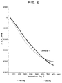
- Figure 6 shows a thermal expansion measurement on a 2 inch (50 mm) sample of the material composition of Example 1 which gives an average negative coefficient of expansion of -78 x 10 -7 /°C (measured between 25°-150°C) and a moderate level of hysteresis as evidenced by the very similar heating and cooling curves.
- a composition containing on a weight percent basis 49.0% SiO 2 , 37.1% Al 2 O 3 , 9.6% Li 2 O and 4.3% TiO 2 is melted at 1600°C in a crucible then the glass is cast onto a cold steel plate to form a disc of about 0.25 to 0.5 in (6.3 mm to 12.7 mm) thick.
- the slab is then cut into bars and heated to 715°C at 300°C/hr, to 765°C at 140°C/hr, to 1300°C at 300°C/hr and held at this temperature for 4 hours, then cooled at the furnace cooling rate for several hours to less than about 100°C.
- the cooled bar is subjected to four cycles of reheating to 800°C and cooling to ambient temperatures to minimize hysteresis.
- Example 2 A composition identical to that of Example 2 was treated to the same conditions except that it is held at 1300°C for only 0.5 hours before cooling, and it was not subjected to further heating cycles.
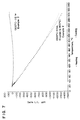
- Figure 7 shows a thermal expansion measurement on the material composition of Examples 2 and 3.
- Example 2 shows an average negative coefficient of expansion of -52.8 x 10 -7 /°C (measured between 25°-150°C) and essentially no hysteresis as evidenced by the very similar heating and cooling curves.
- Example 3 shows zero expansion over the same temperature range without hysteresis.
- the composition be maintained at the top temperature of 1300°C for about 3 to 4 hours to obtain a highly ordered crystal phase. It is evident that the material of Example 3 which was only maintained at 1300°C for 0.5 hour has a zero coefficient of expansion and is still relatively disordered.
- the heat recycling steps are not essential for achieving satisfactory hysteresis. However, 1 to 4 heat recycling steps may be beneficial.
- the heating rate is about 300°C per hour and the bar is maintained at 800°C for about 1 hour each cycle.
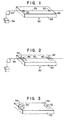
- the optical fiber reflective grating device 20 has a substrate 22 formed from a flat block of a negative expansion material, such as beta-eucryptite.
- An optical fiber 24 having at least one UV-induced reflective grating 26 written therein is mounted on the surface 28 and attached at either end of the surface at points 30 and 32. It is important that the fiber is always straight and not subject to compression as a result of the negative expansion and thus the fiber is usually mounted under tension. Before attachment the fiber is placed under a controlled tension, as shown schematically by the use of a weight 34. The proper choice of tension assures that the fiber is not under compression at all anticipated use temperatures. However, the fiber can be under tension at all anticipated use temperatures. The required degree of tension to compensate for the negative expansion in a particular application can readily be calculated by those with skill in this art.
- the attachment material could be an organic polymer, for example an epoxy cement, an inorganic frit, for example ground glass, ceramic or glass-ceramic material, or a metal.
- the fiber is tacked to the substrate with a UV-cured epoxy adhesive. Mechanical means for attaching the fiber can also be used.
- the optical fiber reflective grating is supplied with a coating material surrounding the fiber.
- the coating in the grating region of the fiber is left intact while it is removed in the substrate attachment region at each end of the grating.
- the device can have the coating completely removed between the attachment locations. Removal of the coating can be accomplished by one of two methods : a non-contact, non-chemical stripping mechanism or by conventional chemical stripping.
- the fiber is not attached directly to the substrate.
- Bonding pads 40, 42 made from a material differing from the substrate, for example a glass or a ceramic, are attached to the substrate at either end.
- the fiber 26 is mounted to the pads at points 44, 46 These pads afford better attachment properties of the pad to the fiber than could be achieved from the substrate directly to the fiber because of the large thermal expansion mismatch.
- Suitable pad materials have a coefficient of thermal expansion intermediate between that of the fiber and the substrate for example between -50 and + 5 x 10 -7 , preferably about -20 x 10 -7 .
- the pad could be a fused silica with a coefficient of expansion closely matching that of the fiber.
- the pad allows the stress of this joint induced by both the thermal mismatch and the tension of the fiber, to be spread out over a wider area, lessening the chances of cracking and detachment.
- the attachment materials for the fiber and pad connections are similar to those used for mounting the fiber directly to the substrate, for example, an epoxy cement, an inorganic frit, for example ground glass, ceramic or glass-ceramic material, or a metal.
- the negative expansion of the substrate material 22 is used to create a clamping force on the fiber.
- the attachment feature which might be a hole or channel 50, 52 in a raised portion 54, 56 of the substrate, is formed in the substrate at room temperature with a gap that is very slightly smaller than the fiber.
- the substrate expands and allows the insertion of the fiber 24 into the channel 50. Warming of the substrate then causes substrate contraction and creates a clamping force for holding the fiber in the channel.
- the fiber 24 is attached to the substrate at points 30, 32 and the intermediate fiber length 60 is cushioned by a low modulus damping material 62.
- This low-modulus material for example a silicone rubber coating surrounding the fiber or a pad of a silicone rubber, a natural or synthetic rubber or mixtures thereof, between the fiber and the substrate protects the fiber reflective grating against external perturbations such as mechanical shock or vibration. Bowing of the fiber is also minimized.
- the low modulus material is adhesively attached to the fiber and the substrate.
- Mounting the fiber under tension will alter the optical properties of the device (for example, the center wavelength of a grating). This can be addressed by biasing the device with a reflective grating written therein to account for the tension, or it can be done by mounting a fiber, for example a germania doped silica fiber, without a reflective grating written therein under tension and then exposing the fiber to UV light in order to fabricate the grating in the device in situ .
- the temperature sensitivity of the center wavelength is about 0.0125 nm/°C
- the stress sensitivity of the center wavelength is 0.125 nm shift for 9g of tension
- the bare fiber has a diameter of 125 microns
- a coated fiber has a diameter of 250 microns.
- the strength of the fiber is >200 kpsi and therefore has a very high reliability.
- the grating was written in a photorefractive-sensitive fiber, Corning SMF-228 fiber, and the fiber was hydrogen loaded at 100 atmospheres in a hydrogen chamber for one week. After removal of the fiber from the hydrogen chamber, a length of approximately 30 mm of coating was removed by mechanical stripping and the fiber was exposed to 240 nm laser irradiation to create the grating. The fiber was then mounted to a substrate of beta-eucryptite, prepared essentially according to the method of Example 2, under a 10 kpsi tension using a UV-curable epoxy adhesive. The assembled grating was heated to 125°C for 2 hours to out diffuse any remaining hydrogen and to eliminate low stability UV-induced traps. The fiber was thermally cycled between -40°C and +125°C.
- a reference fiber was treated in exactly the same way, except it was not attached to a substrate.
- the grating center wavelength ( Figure 8) varies by approximately 1.9 nm from -40°C to +125°C when not attached to the substrate and by only 0.2 nm when attached to the substrate.
- optical fiber couplers and optical waveguides could be athermalized by attachment to a negative expansion substrate.
- An optical fiber fused coupler has two or more fibers fused together at one or more points along their length and is mounted on a substrate.
- Such couplers are thermally sensitive which results in a certain amount of thermal instability.
- biconically tapered couplers in which interferometric effects are used, for example a Mach-Zehnder interferometer.
- Such couplers can be athermalized by mounting the coupler to a negative expansion substrate, such as the beta-eucryptite described in Example 2 above.
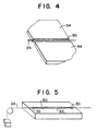
- a fused biconical coupler device 70 which includes a negative expansion substrate 72 to which are mounted two fibers 74, 76.
- the fibers are fused together at regions 78, 80.
- the fibers are attached to the substrate near the ends at locations 82, 84 in the same manner as described above for the optical fiber reflective grating.
- Waveguides can be defined, for example, in optical fibers or planar substrates. Such waveguides are thermally sensitive which results in a certain amount of thermal instability. Such waveguides can be athermalized by mounting the waveguide to a negative expansion substrate, such as the beta-eucryptite described in Example 2 above.
- a planar waveguide device 90 which includes a negative expansion substrate 92 on which is adhesively mounted a layer of material 94 in which a planar waveguide 96 is fabricated by methods well known to those skilled in this art.
- the waveguide material can be, for example, a doped silica such as a germania silicate, other suitable glass compositions, polymers and semiconductors, including semiconductors with gain, such as laser diodes.
- the device of this invention is a completely passive system and mechanically simple, and demonstrates athermalization.
- the method of producing the device is advantageous because it provides temperature compensated optical devices which tolerate shock and vibration and are thermally stable.
Claims (27)
- Un dispositif optique athermique comprenant un substrat à dilatation négative présentant une surface supérieure et comprenant une matière à coefficient de dilatation thermique négatif et un composant optique à dilatation positive sensible à la chaleur fixé à ladite surface supérieure dudit substrat en au moins deux emplacements mutuellement espacés.
- Un dispositif selon la revendication 1, dans lequel le substrat est un substrat d'un seul tenant qui comprend une matière ayant un coefficient de dilatation thermique intrinsèque négatif.
- Un dispositif selon la revendication 1 ou 2, dans lequel le substrat présente un coefficient de dilatation thermique négatif compris entre -30x10-7/°C et -90x10-7/°C.
- Un dispositif selon l'une quelconque des revendications 1 à 3, dans lequel le substrat comprend une vitrocéramique.
- Un dispositif selon la revendication 4, dans lequel le substrat comprend une vitrocéramique à base d'eucryptite bêta.
- Un dispositif selon la revendication 4 ou 5, dans lequel la vitrocéramique comprend, en pourcentages pondéraux, 43 à 55 % de SiO2, 31 à 42 % d'Al2O3, 8 à 11 % de Li2O, 2 à 6 % de TiO2 et 0 à 4 % de ZrO2.
- Un dispositif selon l'une quelconque des revendications 1 à 6, dans lequel le dispositif est fixé par une couche de matière de fixation.
- Un dispositif selon la revendication 7, dans lequel la matière de fixation est un polymère, une fritte ou un métal.
- Un dispositif selon la revendication 8, dans lequel la matière de fixation est un adhésif époxy.
- Un dispositif selon l'une quelconque des revendications 1 à 9, dans lequel le composant optique est un réseau de fibre optique.
- Un dispositif selon l'une quelconque des revendications 1 à 9, dans lequel le composant optique est un coupleur de fibres optiques, le coupleur comprenant au moins deux fibres optiques fondues ensemble en un ou plusieurs points le long de leur longueur.
- Un dispositif selon l'une quelconque des revendications 1 à 9, dans lequel le composant optique est un guide d'ondes.
- Un dispositif selon la revendications 12, dans lequel le guide d'ondes est un guide d'ondes plan.
- Un dispositif selon la revendications 10, dans lequel le réseau de fibre optique est présent dans la fibre optique entre deux extrémités du substrat et à une certaine distance de celles-ci.
- Un dispositif selon la revendication 14, dans lequel la fibre optique est fixée au substrat en un premier et un deuxième emplacements mutuellement espacés, le premier emplacement étant situé entre le réseau et une première extrémité du substrat et le deuxième emplacement étant situé entre le réseau et une deuxième extrémité du substrat.
- Un dispositif selon l'une quelconque des revendications 10, 14 et 15, dans lequel la fibre est maintenue en tension à toutes les températures d'utilisation envisagées.
- Un dispositif selon l'une quelconque des revendications 10 et 14 à 16, comprenant en outre un plot de connexion présentant un coefficient de dilatation intermédiaire entre celui de la fibre et celui du substrat monté entre la fibre optique et le substrat en chacun des emplacements de fixation, la fibre optique étant solidarisée à chaque plot de connexion et chaque plot de connexion étant fixé au substrat.
- Un dispositif selon l'une quelconque des revendications 10 et 14 à 17, comprenant en outre une matière d'amortissement à bas module reliée à sensiblement toute la longueur de la fibre entre les emplacements de fixation.
- Un dispositif selon l'une quelconque des revendications 10 et 14 à 18, dans lequel chaque emplacement de fixation comprend un canal dimensionné de manière à recevoir la fibre à une température inférieure à toutes les températures d'utilisation envisagées pour le dispositif et à bloquer la fibre aux températures d'utilisation normale.
- Un procédé de production d'un dispositif optique athermique selon l'une quelconque des revendications 1 à 19, qui comprend le montage du composant optique à dilatation positive sensible à la chaleur sur une surface du substrat à dilatation négative et la fixation du composant à celle-ci en au moins deux emplacements mutuellement espacés.
- Un procédé selon la revendication 20 pour la production d'un dispositif selon la revendication 16, dans lequel il est appliqué une tension suffisante à la fibre optique avant l'opération de fixation au substrat pour maintenir la fibre en tension à toutes les température d'utilisation envisagées.
- Un procédé selon la revendication 20 ou 21 pour la production d'un dispositif selon la revendication 19, qui comprend les opérations consistant à refroidir le substrat à une température inférieure à toutes les températures d'utilisation envisagées pour le dispositif, à introduire la fibre dans le canal en chaque emplacement de fixation et à chauffer le substrat dans la plage de températures d'utilisation normale afin d'immobiliser la fibre.
- Un procédé selon l'une quelconque des revendications 20 à 22 pour la production d'un dispositif à réseau de fibre optique athermique, comprenant le montage d'une fibre optique sensible photoréfractive sur le substrat à dilatation négative, l'application d'une tension suffisante à la fibre optique pour maintenir la fibre en tension à toutes les températures d'utilisation envisagées, la fixation de la fibre optique au substrat en au moins deux emplacements mutuellement espacés, et l'exposition de la fibre optique à de la lumière ultraviolette avant ou bien après l'opération de montage à l'effet de définir au moins un réseau optique dans celle-ci de sorte que le réseau se situe entre et à distance de chaque extrémité du substrat.
- Un dispositif optique athermique comprenant une fibre optique comportant un réseau d'indice de réfraction, dans lequel la fibre optique est fixée à la surface supérieure d'au moins deux emplacements mutuellement espacés d'un substrat à dilatation négative présentant un coefficient de dilatation thermique négatif tel que la longueur d'onde centrale de réflexion du réseau d'indice de réfraction soit sensiblement indépendante de la température sur la plage des températures de fonctionnement du réseau d'indice de réfraction, le substrat comprenant une matière ayant un coefficient de dilatation thermique intrinsèque négatif.
- Un dispositif selon la revendication 24, dans lequel le substrat est un substrat d'un seul tenant.
- Un procédé selon la revendication 24 ou 25, dans lequel la plage de fonctionnement comprend au moins une portion de la plage allant de -40 à +125 %.
- Un procédé selon l'une quelconque des revendications 24 à 26, dans lequel la fibre optique est une fibre à base de silice.
Applications Claiming Priority (3)
| Application Number | Priority Date | Filing Date | Title |
|---|---|---|---|
| US1005896P | 1996-01-16 | 1996-01-16 | |
| US10058P | 1996-01-16 | ||
| PCT/US1996/013062 WO1997026572A1 (fr) | 1996-01-16 | 1996-08-07 | Dispositif optique athermique |
Publications (2)
| Publication Number | Publication Date |
|---|---|
| EP0875012A1 EP0875012A1 (fr) | 1998-11-04 |
| EP0875012B1 true EP0875012B1 (fr) | 2002-10-23 |
Family
ID=21743603
Family Applications (2)
| Application Number | Title | Priority Date | Filing Date |
|---|---|---|---|
| EP96929677A Expired - Lifetime EP0875012B1 (fr) | 1996-01-16 | 1996-08-07 | Dispositif optique athermique |
| EP97924492A Withdrawn EP0880718A4 (fr) | 1996-01-16 | 1997-01-16 | Dispositif optique athermique |
Family Applications After (1)
| Application Number | Title | Priority Date | Filing Date |
|---|---|---|---|
| EP97924492A Withdrawn EP0880718A4 (fr) | 1996-01-16 | 1997-01-16 | Dispositif optique athermique |
Country Status (11)
| Country | Link |
|---|---|
| US (1) | US6087280A (fr) |
| EP (2) | EP0875012B1 (fr) |
| JP (2) | JP2000503415A (fr) |
| KR (2) | KR19990077274A (fr) |
| CN (2) | CN1207812A (fr) |
| AT (1) | ATE226737T1 (fr) |
| AU (2) | AU722410B2 (fr) |
| CA (2) | CA2242676A1 (fr) |
| DE (1) | DE69624505T2 (fr) |
| TW (1) | TW314601B (fr) |
| WO (2) | WO1997026572A1 (fr) |
Families Citing this family (63)
| Publication number | Priority date | Publication date | Assignee | Title |
|---|---|---|---|---|
| WO1997014983A1 (fr) * | 1995-10-16 | 1997-04-24 | Sumitomo Electric Industries, Ltd. | Reseau de diffraction a fibre optique, procede de fabrication et source lumineuse laser |
| US7254297B1 (en) | 1996-01-16 | 2007-08-07 | Corning Incorporated | Athermal optical devices employing negative expansion substrates |
| US6490394B1 (en) | 1996-01-16 | 2002-12-03 | Corning Incorporated | Athermal optical device |
| US5721802A (en) * | 1996-06-13 | 1998-02-24 | Corning Incorporated | Optical device and fusion seal |
| US5926599A (en) * | 1996-06-13 | 1999-07-20 | Corning Incorporated | Optical device and fusion seal |
| US5694503A (en) * | 1996-09-09 | 1997-12-02 | Lucent Technologies Inc. | Article comprising a temperature compensated optical fiber refractive index grating |
| AUPO745897A0 (en) | 1997-06-19 | 1997-07-10 | Uniphase Fibre Components Pty Limited | Temperature stable bragg grating package with post tuning for accurate setting of center frequency |
| US6011886A (en) * | 1997-10-16 | 2000-01-04 | Lucent Technologies Inc. | Recoatable temperature-insensitive long-period gratings |
| US6081641A (en) * | 1997-11-03 | 2000-06-27 | Applied Fiber Optics, Inc. | Thermal compensated fused-fiber dense wavelength division multiplexer |
| AU736870B2 (en) * | 1997-11-24 | 2001-08-02 | Koheras A/S | Temperature stabilization of optical waveguides |
| FR2772488B1 (fr) * | 1997-12-16 | 2001-12-28 | France Telecom | Dispositif de stabilisation d'un reseau de bragg vis a vis de la temperature, comportant deux materiaux de coefficients de dilatation thermique eloignes l'un de l'autre |
| FR2772487B1 (fr) * | 1997-12-16 | 2002-02-01 | France Telecom | Procede de realisation d'un dispositif de stabilisation de reseau de bragg vis a vis de la temperature |
| EP1064576A1 (fr) | 1998-03-17 | 2001-01-03 | Minnesota Mining And Manufacturing Company | Fibres optiques a compensation passive |
| KR100274807B1 (ko) * | 1998-06-24 | 2000-12-15 | 김효근 | 브래그격자 필터용 광섬유 및 그를 이용한 브래그 격자 필터 |
| US6506699B1 (en) * | 1998-10-23 | 2003-01-14 | Kabushiki Kaisha Ohara | Negative thermal expansion glass ceramic and method for producing the same |
| AU6407699A (en) | 1998-11-06 | 2000-05-29 | Corning Incorporated | Athermal optical waveguide grating device |
| IT1305113B1 (it) * | 1998-12-21 | 2001-04-10 | Cselt Centro Studi Lab Telecom | Dispositivo a reticolo di bragg in fibra ottica con compensazionepassiva della temperatura. |
| JP3901892B2 (ja) | 1999-02-24 | 2007-04-04 | 日本電気硝子株式会社 | 温度補償用部材、それを用いた光通信デバイスおよび温度補償用部材の製造方法 |
| JP2000266943A (ja) * | 1999-03-12 | 2000-09-29 | Nippon Electric Glass Co Ltd | 光通信用温度補償デバイス |
| JP2000352633A (ja) | 1999-04-05 | 2000-12-19 | Nec Corp | 光導波路、それを用いた導波路型光デバイス、及び導波路型光デバイスの製造方法 |
| JP3566129B2 (ja) * | 1999-04-06 | 2004-09-15 | 株式会社フジクラ | 温度補償型光ファイバブラッググレーティング |
| BR0009973A (pt) * | 1999-04-23 | 2002-01-08 | Corning Inc | Método de produção de substrato de guia de onda ótica de expansão térmica negativa estabilizada e um substrato de vidro-cerâmica |
| US6477299B1 (en) * | 1999-04-23 | 2002-11-05 | Corning Incorporated | Environmentally stable athermalizes optical fiber grating device and method of making a stabilized device |
| KR20020038675A (ko) | 1999-07-07 | 2002-05-23 | 모리 데쯔지 | 온도 보상용 부재 및 이를 이용한 광 통신 디바이스 |
| US6317528B1 (en) * | 1999-08-23 | 2001-11-13 | Corning Incorporated | Temperature compensated integrated planar bragg grating, and method of formation |
| DE19943387A1 (de) * | 1999-09-10 | 2001-11-22 | Siemens Ag | Verfahren zur Herstellung eines optischen Gitters auf einem optischen Leiter und Anordnung mit einem solchen Gitter und solchen Leiter |
| WO2001035133A1 (fr) * | 1999-11-11 | 2001-05-17 | Koheras A/S | Guide d'ondes optique athermique compact utilisant l'amplification par dilatation thermique |
| DE10004384C2 (de) * | 2000-02-02 | 2003-04-03 | Daimler Chrysler Ag | Anordnung und Verfahren zur Erfassung von Dehnungen und Temperaturen und deren Veränderungen einer auf einem Träger, insbesondere einem aus Metall, Kunststoff oder Keramik bestehenden Träger, applizierten Deckschicht |
| JP4702690B2 (ja) * | 2000-03-29 | 2011-06-15 | 日本電気硝子株式会社 | 結晶化ガラス |
| JP3928331B2 (ja) | 2000-05-09 | 2007-06-13 | 住友電気工業株式会社 | 光導波路デバイスおよびその製造方法 |
| JP4704585B2 (ja) * | 2000-07-07 | 2011-06-15 | 株式会社オハラ | 低膨張透明結晶化ガラス、結晶化ガラス基板及び光導波路素子 |
| US6381387B1 (en) * | 2000-08-02 | 2002-04-30 | Networks Photonics, Inc. | Athermalization of a wavelength routing element |
| JP4773608B2 (ja) | 2000-09-28 | 2011-09-14 | 株式会社オハラ | ガラスセラミックス及び温度補償部材 |
| JP2004510676A (ja) * | 2000-10-02 | 2004-04-08 | コーニング インコーポレイテッド | リチウムアルミノケイ酸塩セラミック |
| WO2002039160A1 (fr) * | 2000-11-09 | 2002-05-16 | Cambridge University Technical Services Ltd. | Plate-forme a coefficient de dilatation thermique regule |
| CA2357242A1 (fr) * | 2001-02-22 | 2002-08-22 | Teraxion Inc. | Enveloppe athermique reglable pour dispositifs a fibres optiques |
| EP1424575A1 (fr) * | 2001-08-07 | 2004-06-02 | Nippon Electric Glass Co., Ltd | Materiau de base pour dispositif de communication optique, et dispositif de communication optique |
| US6603892B1 (en) | 2001-10-24 | 2003-08-05 | Lightwave Microsystems Corporation | Mechanical beam steering for optical integrated circuits |
| US6987909B1 (en) | 2001-11-30 | 2006-01-17 | Corvis Corporation | Optical systems and athermalized optical component apparatuses and methods for use therein |
| US20030125184A1 (en) * | 2001-12-21 | 2003-07-03 | Schott Glas | Glass ceramic product with variably adjustable zero crossing of the CTE-T curve |
| US6738545B1 (en) * | 2002-03-18 | 2004-05-18 | Lightwave Microsystems Corporation | Athermal AWG and AWG with low power consumption using groove of changeable width |
| US6975793B2 (en) * | 2002-03-18 | 2005-12-13 | Lightwave Microsystems Corporation | Method and apparatus facilitating mechanical beam steering for optical integrated circuits |
| TW584749B (en) * | 2002-12-30 | 2004-04-21 | Chow-Shing Shin | Temperature compensation method of fiber device |
| US7004911B1 (en) * | 2003-02-24 | 2006-02-28 | Hosheng Tu | Optical thermal mapping for detecting vulnerable plaque |
| US7171077B2 (en) * | 2003-04-03 | 2007-01-30 | Lxsix Photonics Inc. | Package for temperature sensitive optical device |
| JP2005070751A (ja) * | 2003-08-05 | 2005-03-17 | Nippon Electric Glass Co Ltd | 光通信デバイス用基材、その製造方法およびそれを用いた光通信デバイス |
| US20060245692A1 (en) * | 2004-04-01 | 2006-11-02 | Lxsix Photonics Inc. | Package for temperature sensitive optical device |
| JP2006206407A (ja) * | 2005-01-31 | 2006-08-10 | Kyocera Kinseki Corp | 水晶結晶とその育成方法 |
| TWI249470B (en) * | 2005-03-09 | 2006-02-21 | Univ Nat Central | Structure and method of thermal stress compensation |
| JP2007108325A (ja) | 2005-10-12 | 2007-04-26 | Oki Electric Ind Co Ltd | 波長調整装置および波長調整方法 |
| US20070221132A1 (en) * | 2006-03-24 | 2007-09-27 | General Electric Company | Composition, coating, coated article, and method |
| JP4201023B2 (ja) | 2006-06-06 | 2008-12-24 | 沖電気工業株式会社 | ファイバブラッググレーティング装置 |
| US20080141938A1 (en) * | 2006-12-13 | 2008-06-19 | General Electric Company | Processing apparatus, coated article and method |
| SE532721C2 (sv) * | 2007-10-01 | 2010-03-23 | Mircona Ab | Produkt med vibrationsdämpande keramisk beläggning för spånavskiljning vid materialbearbetning samt metod för dess tillverkning |
| FR2959506B1 (fr) * | 2010-04-30 | 2014-01-03 | Thales Sa | Materiau composite ceramique a base de beta-eucryptite et d'un oxyde et procede de fabrication dudit materiau. |
| JP5435044B2 (ja) * | 2012-01-13 | 2014-03-05 | 沖電気工業株式会社 | ファイバブラッググレーティング装置 |
| US9850172B2 (en) | 2014-10-23 | 2017-12-26 | Industrial Technology Research Institute | Ceramic powder, method of manufacturing the same, and method for laser sinter molding |
| JP6815087B2 (ja) * | 2016-03-28 | 2021-01-20 | 日鉄ケミカル&マテリアル株式会社 | 球状ユークリプタイト粒子およびその製造方法 |
| NL2017647B1 (en) * | 2016-10-20 | 2018-04-26 | Fugro Tech Bv | Probe for determining soil properties |
| JP6889922B2 (ja) * | 2017-08-31 | 2021-06-18 | 三星ダイヤモンド工業株式会社 | ガラス基板の残留応力低減方法及びガラス基板の残留応力低減装置 |
| US11125936B2 (en) | 2019-02-26 | 2021-09-21 | The Government Of The United States Of America, As Represented By The Secretary Of The Navy | Thermal insulator for fiber optic components |
| CN114249529B (zh) * | 2021-12-06 | 2024-03-01 | 北京北旭电子材料有限公司 | 锂铝硅系填料组合物、锂铝硅系填料及其制备方法、玻璃封接材料及其应用 |
| CN115614779A (zh) * | 2022-09-08 | 2023-01-17 | 中国航发湖南动力机械研究所 | 一种火焰筒及其自适应冷却气量调节方法 |
Family Cites Families (20)
| Publication number | Priority date | Publication date | Assignee | Title |
|---|---|---|---|---|
| DE1421927A1 (de) * | 1960-03-26 | 1968-12-12 | Siemens Ag | Kristalliner oder glasig-kristalliner Werkstoff mit negativem oder sehr kleinem thermischem Ausdehnungskoeffizienten |
| DE1596858B1 (de) * | 1967-06-29 | 1970-05-14 | Jenaer Glaswerk Schott & Gen | Glasversaetze zum Herstellen von durchsichtigen ss-Eukryptitmischkristall-haltigen Glaskeramiken |
| US3812689A (en) * | 1972-05-26 | 1974-05-28 | Corning Glass Works | Method of making glass-ceramic articles |
| SE409474B (sv) * | 1975-05-13 | 1979-08-20 | Wennborg Ab C J | Sett vid kontinuerlig och diskontinuerlig elektrokemisk rengoring av legerade stal, serskilt rostfritt stal i form av band, stang, profiler, trad, ror och styckegods med ytor bemengda av mineraloljor och syntetiska ... |
| US4042403A (en) * | 1975-05-19 | 1977-08-16 | Corning Glass Works | Thermally stable glass-ceramic articles |
| US4083727A (en) * | 1977-01-07 | 1978-04-11 | Corning Glass Works | Glass-ceramics with magnetic surface films |
| DE2740053A1 (de) * | 1977-09-06 | 1979-05-03 | Klaus Prof Dr Med Gersonde | Verwendung von allosterischen effektoren mit hilfe von lipidvesikeln ueber eine irreversible inkorporierung zwecks verbesserter o tief 2 -entladung des haemoglobins in erythrozyten |
| US4209229A (en) * | 1978-09-25 | 1980-06-24 | Corning Glass Works | Glass-ceramic coated optical waveguides |
| DE3586052D1 (de) * | 1984-08-13 | 1992-06-17 | United Technologies Corp | Verfahren zum einlagern optischer gitter in faseroptik. |
| US4814297A (en) * | 1987-04-01 | 1989-03-21 | Corning Glass Works | Strengthened glass article and method |
| US5021395A (en) * | 1988-07-01 | 1991-06-04 | E. I. Du Pont De Nemours And Company | Process for making superconductors and their precursors |
| US5126316A (en) * | 1988-08-24 | 1992-06-30 | E. I. Du Pont De Nemours And Company | Bi2 Sr3-x Yx Cu2 O8+y superconducting metal oxide compositions |
| US5042898A (en) * | 1989-12-26 | 1991-08-27 | United Technologies Corporation | Incorporated Bragg filter temperature compensated optical waveguide device |
| US5186729A (en) * | 1991-04-26 | 1993-02-16 | Center For Innovative Technology | Method of making in-situ whisker reinforced glass ceramic |
| CA2083983A1 (fr) * | 1992-01-27 | 1993-07-28 | Kishor P. Gadkaree | Composition a faible expansion pour l'emballage des coupleurs de guide d'onde optique |
| JP2516537B2 (ja) * | 1992-09-14 | 1996-07-24 | 株式会社オハラ | 低膨張透明結晶化ガラス |
| US5322559A (en) * | 1993-05-11 | 1994-06-21 | State Of Oregon Acting By And Through The State Board Of Higher Education On Behalf Of Oregon State University | Negative thermal expansion material |
| US5433778A (en) * | 1993-05-11 | 1995-07-18 | The State Of Oregon Acting By And Through The State Board Of Higher Education On Behalf Of Oregon State University | Negative thermal expansion material |
| JP2668057B2 (ja) * | 1994-09-13 | 1997-10-27 | 株式会社オハラ | 低膨張透明ガラスセラミックス |
| US5514360A (en) * | 1995-03-01 | 1996-05-07 | The State Of Oregon, Acting By And Through The Oregon State Board Of Higher Education, Acting For And On Behalf Of Oregon State University | Negative thermal expansion materials |
-
1996
- 1996-08-07 DE DE69624505T patent/DE69624505T2/de not_active Expired - Fee Related
- 1996-08-07 JP JP09525962A patent/JP2000503415A/ja not_active Ceased
- 1996-08-07 AT AT96929677T patent/ATE226737T1/de not_active IP Right Cessation
- 1996-08-07 CA CA002242676A patent/CA2242676A1/fr not_active Abandoned
- 1996-08-07 KR KR1019980705420A patent/KR19990077274A/ko not_active Application Discontinuation
- 1996-08-07 WO PCT/US1996/013062 patent/WO1997026572A1/fr not_active Application Discontinuation
- 1996-08-07 CN CN96199621A patent/CN1207812A/zh active Pending
- 1996-08-07 AU AU68973/96A patent/AU722410B2/en not_active Ceased
- 1996-08-07 EP EP96929677A patent/EP0875012B1/fr not_active Expired - Lifetime
- 1996-10-24 TW TW085113088A patent/TW314601B/zh active
-
1997
- 1997-01-16 CA CA002243200A patent/CA2243200A1/fr not_active Abandoned
- 1997-01-16 EP EP97924492A patent/EP0880718A4/fr not_active Withdrawn
- 1997-01-16 JP JP9527710A patent/JP2000503967A/ja active Pending
- 1997-01-16 US US08/785,336 patent/US6087280A/en not_active Expired - Lifetime
- 1997-01-16 AU AU29903/97A patent/AU725293B2/en not_active Ceased
- 1997-01-16 KR KR10-1998-0705421A patent/KR100455908B1/ko not_active IP Right Cessation
- 1997-01-16 CN CN97191685A patent/CN1208396A/zh active Pending
- 1997-01-16 WO PCT/US1997/000982 patent/WO1997028480A2/fr active IP Right Grant
Also Published As
| Publication number | Publication date |
|---|---|
| CN1207812A (zh) | 1999-02-10 |
| KR19990077274A (ko) | 1999-10-25 |
| CA2242676A1 (fr) | 1997-07-24 |
| ATE226737T1 (de) | 2002-11-15 |
| AU725293B2 (en) | 2000-10-12 |
| AU6897396A (en) | 1997-08-11 |
| JP2000503415A (ja) | 2000-03-21 |
| JP2000503967A (ja) | 2000-04-04 |
| AU722410B2 (en) | 2000-08-03 |
| DE69624505D1 (de) | 2002-11-28 |
| EP0880718A2 (fr) | 1998-12-02 |
| EP0880718A4 (fr) | 1999-09-22 |
| EP0875012A1 (fr) | 1998-11-04 |
| AU2990397A (en) | 1997-08-22 |
| CN1208396A (zh) | 1999-02-17 |
| KR100455908B1 (ko) | 2005-04-13 |
| US6087280A (en) | 2000-07-11 |
| WO1997028480A2 (fr) | 1997-08-07 |
| TW314601B (fr) | 1997-09-01 |
| KR19990077275A (ko) | 1999-10-25 |
| WO1997028480A3 (fr) | 1997-11-20 |
| WO1997026572A1 (fr) | 1997-07-24 |
| DE69624505T2 (de) | 2003-06-26 |
| CA2243200A1 (fr) | 1997-08-07 |
Similar Documents
| Publication | Publication Date | Title |
|---|---|---|
| EP0875012B1 (fr) | Dispositif optique athermique | |
| WO1997028480A9 (fr) | Dispositif optique athermique | |
| US6209352B1 (en) | Methods of making negative thermal expansion glass-ceramic and articles made thereby | |
| EP0828169A2 (fr) | Réseau d'indice de réfraction dans une fibre optique avec compensation de la température | |
| US6490394B1 (en) | Athermal optical device | |
| JP2003020254A (ja) | 結晶化ガラス | |
| KR20020038675A (ko) | 온도 보상용 부재 및 이를 이용한 광 통신 디바이스 | |
| US6603900B1 (en) | Athermal optical waveguide grating device | |
| Weidman et al. | A novel negative expansion substrate material for athermalizing fiber Bragg gratings | |
| US6477299B1 (en) | Environmentally stable athermalizes optical fiber grating device and method of making a stabilized device | |
| AU772223B2 (en) | Temperature compensated device for use in optical communication | |
| US7254297B1 (en) | Athermal optical devices employing negative expansion substrates | |
| JP4702690B2 (ja) | 結晶化ガラス | |
| WO2001035133A1 (fr) | Guide d'ondes optique athermique compact utilisant l'amplification par dilatation thermique | |
| US6465380B1 (en) | Athermal optical device | |
| US20050175310A1 (en) | Substrate for optical communication device, method for production thereof and optical communication device using the same | |
| JP2001072463A (ja) | 温度補償用部材及びそれを用いた光通信デバイス | |
| JP2005162602A (ja) | 温度補償用部材の製造方法 | |
| JP2004295156A (ja) | 光通信用温度補償デバイス | |
| JP2002071961A (ja) | 光学装置 | |
| JP2005035886A (ja) | 温度補償用部材及びそれを用いた光通信デバイス |
Legal Events
| Date | Code | Title | Description |
|---|---|---|---|
| PUAI | Public reference made under article 153(3) epc to a published international application that has entered the european phase |
Free format text: ORIGINAL CODE: 0009012 |
|
| 17P | Request for examination filed |
Effective date: 19980813 |
|
| AK | Designated contracting states |
Kind code of ref document: A1 Designated state(s): AT BE CH DE DK ES FI FR GB GR IE IT LI LU MC NL PT SE |
|
| 17Q | First examination report despatched |
Effective date: 19991104 |
|
| GRAG | Despatch of communication of intention to grant |
Free format text: ORIGINAL CODE: EPIDOS AGRA |
|
| GRAG | Despatch of communication of intention to grant |
Free format text: ORIGINAL CODE: EPIDOS AGRA |
|
| GRAH | Despatch of communication of intention to grant a patent |
Free format text: ORIGINAL CODE: EPIDOS IGRA |
|
| GRAH | Despatch of communication of intention to grant a patent |
Free format text: ORIGINAL CODE: EPIDOS IGRA |
|
| GRAA | (expected) grant |
Free format text: ORIGINAL CODE: 0009210 |
|
| AK | Designated contracting states |
Kind code of ref document: B1 Designated state(s): AT BE CH DE DK ES FI FR GB GR IE IT LI LU MC NL PT SE |
|
| PG25 | Lapsed in a contracting state [announced via postgrant information from national office to epo] |
Ref country code: NL Free format text: LAPSE BECAUSE OF FAILURE TO SUBMIT A TRANSLATION OF THE DESCRIPTION OR TO PAY THE FEE WITHIN THE PRESCRIBED TIME-LIMIT Effective date: 20021023 Ref country code: LI Free format text: LAPSE BECAUSE OF FAILURE TO SUBMIT A TRANSLATION OF THE DESCRIPTION OR TO PAY THE FEE WITHIN THE PRESCRIBED TIME-LIMIT Effective date: 20021023 Ref country code: GR Free format text: LAPSE BECAUSE OF FAILURE TO SUBMIT A TRANSLATION OF THE DESCRIPTION OR TO PAY THE FEE WITHIN THE PRESCRIBED TIME-LIMIT Effective date: 20021023 Ref country code: FI Free format text: LAPSE BECAUSE OF FAILURE TO SUBMIT A TRANSLATION OF THE DESCRIPTION OR TO PAY THE FEE WITHIN THE PRESCRIBED TIME-LIMIT Effective date: 20021023 Ref country code: CH Free format text: LAPSE BECAUSE OF FAILURE TO SUBMIT A TRANSLATION OF THE DESCRIPTION OR TO PAY THE FEE WITHIN THE PRESCRIBED TIME-LIMIT Effective date: 20021023 Ref country code: BE Free format text: LAPSE BECAUSE OF FAILURE TO SUBMIT A TRANSLATION OF THE DESCRIPTION OR TO PAY THE FEE WITHIN THE PRESCRIBED TIME-LIMIT Effective date: 20021023 Ref country code: AT Free format text: LAPSE BECAUSE OF FAILURE TO SUBMIT A TRANSLATION OF THE DESCRIPTION OR TO PAY THE FEE WITHIN THE PRESCRIBED TIME-LIMIT Effective date: 20021023 |
|
| REF | Corresponds to: |
Ref document number: 226737 Country of ref document: AT Date of ref document: 20021115 Kind code of ref document: T |
|
| REG | Reference to a national code |
Ref country code: GB Ref legal event code: FG4D |
|
| REG | Reference to a national code |
Ref country code: CH Ref legal event code: EP |
|
| REG | Reference to a national code |
Ref country code: IE Ref legal event code: FG4D |
|
| REF | Corresponds to: |
Ref document number: 69624505 Country of ref document: DE Date of ref document: 20021128 |
|
| PG25 | Lapsed in a contracting state [announced via postgrant information from national office to epo] |
Ref country code: SE Free format text: LAPSE BECAUSE OF FAILURE TO SUBMIT A TRANSLATION OF THE DESCRIPTION OR TO PAY THE FEE WITHIN THE PRESCRIBED TIME-LIMIT Effective date: 20030123 Ref country code: PT Free format text: LAPSE BECAUSE OF FAILURE TO SUBMIT A TRANSLATION OF THE DESCRIPTION OR TO PAY THE FEE WITHIN THE PRESCRIBED TIME-LIMIT Effective date: 20030123 Ref country code: DK Free format text: LAPSE BECAUSE OF FAILURE TO SUBMIT A TRANSLATION OF THE DESCRIPTION OR TO PAY THE FEE WITHIN THE PRESCRIBED TIME-LIMIT Effective date: 20030123 |
|
| NLV1 | Nl: lapsed or annulled due to failure to fulfill the requirements of art. 29p and 29m of the patents act | ||
| PG25 | Lapsed in a contracting state [announced via postgrant information from national office to epo] |
Ref country code: ES Free format text: LAPSE BECAUSE OF FAILURE TO SUBMIT A TRANSLATION OF THE DESCRIPTION OR TO PAY THE FEE WITHIN THE PRESCRIBED TIME-LIMIT Effective date: 20030429 |
|
| REG | Reference to a national code |
Ref country code: CH Ref legal event code: PL |
|
| ET | Fr: translation filed | ||
| PG25 | Lapsed in a contracting state [announced via postgrant information from national office to epo] |
Ref country code: LU Free format text: LAPSE BECAUSE OF NON-PAYMENT OF DUE FEES Effective date: 20030807 Ref country code: IE Free format text: LAPSE BECAUSE OF NON-PAYMENT OF DUE FEES Effective date: 20030807 |
|
| PLBE | No opposition filed within time limit |
Free format text: ORIGINAL CODE: 0009261 |
|
| STAA | Information on the status of an ep patent application or granted ep patent |
Free format text: STATUS: NO OPPOSITION FILED WITHIN TIME LIMIT |
|
| PG25 | Lapsed in a contracting state [announced via postgrant information from national office to epo] |
Ref country code: MC Free format text: LAPSE BECAUSE OF NON-PAYMENT OF DUE FEES Effective date: 20030831 |
|
| 26N | No opposition filed |
Effective date: 20030724 |
|
| PG25 | Lapsed in a contracting state [announced via postgrant information from national office to epo] |
Ref country code: FR Free format text: LAPSE BECAUSE OF NON-PAYMENT OF DUE FEES Effective date: 20040430 |
|
| REG | Reference to a national code |
Ref country code: IE Ref legal event code: MM4A |
|
| REG | Reference to a national code |
Ref country code: FR Ref legal event code: ST |
|
| PGFP | Annual fee paid to national office [announced via postgrant information from national office to epo] |
Ref country code: GB Payment date: 20050804 Year of fee payment: 10 |
|
| PG25 | Lapsed in a contracting state [announced via postgrant information from national office to epo] |
Ref country code: IT Free format text: LAPSE BECAUSE OF NON-PAYMENT OF DUE FEES Effective date: 20050807 |
|
| PGFP | Annual fee paid to national office [announced via postgrant information from national office to epo] |
Ref country code: DE Payment date: 20050930 Year of fee payment: 10 |
|
| PG25 | Lapsed in a contracting state [announced via postgrant information from national office to epo] |
Ref country code: DE Free format text: LAPSE BECAUSE OF NON-PAYMENT OF DUE FEES Effective date: 20070301 |
|
| GBPC | Gb: european patent ceased through non-payment of renewal fee |
Effective date: 20060807 |
|
| PG25 | Lapsed in a contracting state [announced via postgrant information from national office to epo] |
Ref country code: GB Free format text: LAPSE BECAUSE OF NON-PAYMENT OF DUE FEES Effective date: 20060807 |