EP0874477A2 - Système de transmission de signal et méthode pour le superviser - Google Patents
Système de transmission de signal et méthode pour le superviser Download PDFInfo
- Publication number
- EP0874477A2 EP0874477A2 EP98107310A EP98107310A EP0874477A2 EP 0874477 A2 EP0874477 A2 EP 0874477A2 EP 98107310 A EP98107310 A EP 98107310A EP 98107310 A EP98107310 A EP 98107310A EP 0874477 A2 EP0874477 A2 EP 0874477A2
- Authority
- EP
- European Patent Office
- Prior art keywords
- optical
- signal
- transmission system
- light
- simulator
- Prior art date
- Legal status (The legal status is an assumption and is not a legal conclusion. Google has not performed a legal analysis and makes no representation as to the accuracy of the status listed.)
- Withdrawn
Links
Images


Classifications
-
- H—ELECTRICITY
- H04—ELECTRIC COMMUNICATION TECHNIQUE
- H04B—TRANSMISSION
- H04B10/00—Transmission systems employing electromagnetic waves other than radio-waves, e.g. infrared, visible or ultraviolet light, or employing corpuscular radiation, e.g. quantum communication
- H04B10/25—Arrangements specific to fibre transmission
- H04B10/2507—Arrangements specific to fibre transmission for the reduction or elimination of distortion or dispersion
- H04B10/2537—Arrangements specific to fibre transmission for the reduction or elimination of distortion or dispersion due to scattering processes, e.g. Raman or Brillouin scattering
-
- H—ELECTRICITY
- H04—ELECTRIC COMMUNICATION TECHNIQUE
- H04B—TRANSMISSION
- H04B10/00—Transmission systems employing electromagnetic waves other than radio-waves, e.g. infrared, visible or ultraviolet light, or employing corpuscular radiation, e.g. quantum communication
- H04B10/07—Arrangements for monitoring or testing transmission systems; Arrangements for fault measurement of transmission systems
- H04B10/075—Arrangements for monitoring or testing transmission systems; Arrangements for fault measurement of transmission systems using an in-service signal
- H04B10/077—Arrangements for monitoring or testing transmission systems; Arrangements for fault measurement of transmission systems using an in-service signal using a supervisory or additional signal
- H04B10/0775—Performance monitoring and measurement of transmission parameters
-
- H—ELECTRICITY
- H04—ELECTRIC COMMUNICATION TECHNIQUE
- H04B—TRANSMISSION
- H04B10/00—Transmission systems employing electromagnetic waves other than radio-waves, e.g. infrared, visible or ultraviolet light, or employing corpuscular radiation, e.g. quantum communication
- H04B10/07—Arrangements for monitoring or testing transmission systems; Arrangements for fault measurement of transmission systems
- H04B10/075—Arrangements for monitoring or testing transmission systems; Arrangements for fault measurement of transmission systems using an in-service signal
- H04B10/077—Arrangements for monitoring or testing transmission systems; Arrangements for fault measurement of transmission systems using an in-service signal using a supervisory or additional signal
- H04B10/0777—Monitoring line amplifier or line repeater equipment
-
- H—ELECTRICITY
- H04—ELECTRIC COMMUNICATION TECHNIQUE
- H04B—TRANSMISSION
- H04B10/00—Transmission systems employing electromagnetic waves other than radio-waves, e.g. infrared, visible or ultraviolet light, or employing corpuscular radiation, e.g. quantum communication
- H04B10/07—Arrangements for monitoring or testing transmission systems; Arrangements for fault measurement of transmission systems
- H04B10/075—Arrangements for monitoring or testing transmission systems; Arrangements for fault measurement of transmission systems using an in-service signal
- H04B10/077—Arrangements for monitoring or testing transmission systems; Arrangements for fault measurement of transmission systems using an in-service signal using a supervisory or additional signal
- H04B10/0779—Monitoring line transmitter or line receiver equipment
-
- H—ELECTRICITY
- H04—ELECTRIC COMMUNICATION TECHNIQUE
- H04B—TRANSMISSION
- H04B10/00—Transmission systems employing electromagnetic waves other than radio-waves, e.g. infrared, visible or ultraviolet light, or employing corpuscular radiation, e.g. quantum communication
- H04B10/07—Arrangements for monitoring or testing transmission systems; Arrangements for fault measurement of transmission systems
- H04B10/075—Arrangements for monitoring or testing transmission systems; Arrangements for fault measurement of transmission systems using an in-service signal
- H04B10/079—Arrangements for monitoring or testing transmission systems; Arrangements for fault measurement of transmission systems using an in-service signal using measurements of the data signal
- H04B10/0795—Performance monitoring; Measurement of transmission parameters
- H04B10/07951—Monitoring or measuring chromatic dispersion or PMD
-
- H—ELECTRICITY
- H04—ELECTRIC COMMUNICATION TECHNIQUE
- H04B—TRANSMISSION
- H04B10/00—Transmission systems employing electromagnetic waves other than radio-waves, e.g. infrared, visible or ultraviolet light, or employing corpuscular radiation, e.g. quantum communication
- H04B10/07—Arrangements for monitoring or testing transmission systems; Arrangements for fault measurement of transmission systems
- H04B10/075—Arrangements for monitoring or testing transmission systems; Arrangements for fault measurement of transmission systems using an in-service signal
- H04B10/079—Arrangements for monitoring or testing transmission systems; Arrangements for fault measurement of transmission systems using an in-service signal using measurements of the data signal
- H04B10/0795—Performance monitoring; Measurement of transmission parameters
- H04B10/07953—Monitoring or measuring OSNR, BER or Q
-
- H—ELECTRICITY
- H04—ELECTRIC COMMUNICATION TECHNIQUE
- H04B—TRANSMISSION
- H04B10/00—Transmission systems employing electromagnetic waves other than radio-waves, e.g. infrared, visible or ultraviolet light, or employing corpuscular radiation, e.g. quantum communication
- H04B10/07—Arrangements for monitoring or testing transmission systems; Arrangements for fault measurement of transmission systems
- H04B10/075—Arrangements for monitoring or testing transmission systems; Arrangements for fault measurement of transmission systems using an in-service signal
- H04B10/079—Arrangements for monitoring or testing transmission systems; Arrangements for fault measurement of transmission systems using an in-service signal using measurements of the data signal
- H04B10/0795—Performance monitoring; Measurement of transmission parameters
- H04B10/07955—Monitoring or measuring power
-
- H—ELECTRICITY
- H04—ELECTRIC COMMUNICATION TECHNIQUE
- H04B—TRANSMISSION
- H04B10/00—Transmission systems employing electromagnetic waves other than radio-waves, e.g. infrared, visible or ultraviolet light, or employing corpuscular radiation, e.g. quantum communication
- H04B10/07—Arrangements for monitoring or testing transmission systems; Arrangements for fault measurement of transmission systems
- H04B10/075—Arrangements for monitoring or testing transmission systems; Arrangements for fault measurement of transmission systems using an in-service signal
- H04B10/079—Arrangements for monitoring or testing transmission systems; Arrangements for fault measurement of transmission systems using an in-service signal using measurements of the data signal
- H04B10/0795—Performance monitoring; Measurement of transmission parameters
- H04B10/07957—Monitoring or measuring wavelength
-
- H—ELECTRICITY
- H04—ELECTRIC COMMUNICATION TECHNIQUE
- H04B—TRANSMISSION
- H04B10/00—Transmission systems employing electromagnetic waves other than radio-waves, e.g. infrared, visible or ultraviolet light, or employing corpuscular radiation, e.g. quantum communication
- H04B10/07—Arrangements for monitoring or testing transmission systems; Arrangements for fault measurement of transmission systems
- H04B10/075—Arrangements for monitoring or testing transmission systems; Arrangements for fault measurement of transmission systems using an in-service signal
- H04B10/079—Arrangements for monitoring or testing transmission systems; Arrangements for fault measurement of transmission systems using an in-service signal using measurements of the data signal
- H04B10/0797—Monitoring line amplifier or line repeater equipment
-
- H—ELECTRICITY
- H04—ELECTRIC COMMUNICATION TECHNIQUE
- H04B—TRANSMISSION
- H04B10/00—Transmission systems employing electromagnetic waves other than radio-waves, e.g. infrared, visible or ultraviolet light, or employing corpuscular radiation, e.g. quantum communication
- H04B10/07—Arrangements for monitoring or testing transmission systems; Arrangements for fault measurement of transmission systems
- H04B10/075—Arrangements for monitoring or testing transmission systems; Arrangements for fault measurement of transmission systems using an in-service signal
- H04B10/079—Arrangements for monitoring or testing transmission systems; Arrangements for fault measurement of transmission systems using an in-service signal using measurements of the data signal
- H04B10/0799—Monitoring line transmitter or line receiver equipment
-
- H—ELECTRICITY
- H04—ELECTRIC COMMUNICATION TECHNIQUE
- H04B—TRANSMISSION
- H04B2210/00—Indexing scheme relating to optical transmission systems
- H04B2210/07—Monitoring an optical transmission system using a supervisory signal
- H04B2210/077—Monitoring an optical transmission system using a supervisory signal using a separate fibre
Definitions
- the present invention relates to a signal transmission system and a method for supervising the same, and more particularly, to an optical transmission system and a method for supervising the same using a simulator.
- an optical transmission system using an optical amplifier which directly amplifies a light signal without converting into an electric signal
- a wavelength multiplex type and a two-way transmission type of optical amplifiers have been proposed.
- Such an optical amplifier directly amplifies a light signal in analog fashion using an excitation light without converting the light signal into an electric signal.
- a supervisory light is provided in addition to a main signal to supervise the optical amplifier. The supervisory light is converted into an electrical signal.
- a conventional optical transmission system usually includes an optical transmitter, an optical switching device, etc.
- each device is provided with a loop-back circuit to control the system.
- the loop-back circuit detects and determines a location of the trouble. The location of the trouble would be in the optical transmitter, an optical receiver, an optical fiber, and the like.
- an auxiliary line is used instead.
- each device such as an optical transmitter, an optical receiver and an optical repeater, needs to have an enough margin for itself. If it does, it is difficult to have a wide range of system margin for the whole system.
- the transmission system does not have an enough system margin, a plurality of alternative transmission lines has to be prepared. Even if the current transmission line has a small trouble, the transmission line has to be changed to another one, because the system margin of each transmission line is small.
- an object of the invention is to provide a transmission system, which is able to obtain a large range of system margin.
- an object of the invention is to provide a method for supervising a transmission system so that the system has a large range of margin as a whole.
- a signal transmission system includes an interface unit that monitors the operating condition of each device.
- the signal transmission system also includes a simulator that simulates the transmission quality of the system in response to the operating condition of each device, and controls each device so as to optimize the transmission quality.
- an optical transmission system includes interface units that detect predetermined estimation parameters from the optical transmitter, the repeater and the optical receiver.
- the optical transmission system includes a simulator that simulates the transmission quality of the system in response to the estimation parameters supplied from the interface units.
- the simulator also controls each of the optical transmitter, the repeater and the optical receiver so as to minimize a bit-error rate or to maximize a Q-factor.
- predetermined estimation parameters are monitored from each device to estimate (calculate) a bit-error rate or Q-factor. Then, the simulator calculates the optimum control values so as to minimize the bit-error rate or to maximize the Q-factor, and controls each device in accordance with the optimum control values.
- the optical transmission system has the maximum system margin. Therefore, even if some devices operate out of their margin, the transmission system still operates in a range of its system margin as a whole. Consequently, it is not always required to establish an auxiliary line in addition to the main transmission line.
- Fig. 1 is a conceptual view showing an optical transmission system, according to a first preferred embodiment of the invention.
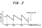
- Fig. 2 is a graph showing a level-diagram used for explaining the operation of the optical transmission system and the method for supervising the same, according to the first preferred embodiment.
- Fig. 3 is a table used for explaining the simulating operation of the optical transmission system and the method for supervising the same, according to the first preferred embodiment.
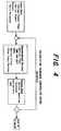
- Fig. 4 is a block diagram showing a simulating calculation flow used for explaining the simulating operation of the optical transmission system and the method for supervising the same, according to the first preferred embodiment.
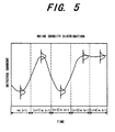
- Fig. 5 is a graph showing a received current waveform used for explaining the simulating operation of the optical transmission system and the method for supervising the same, according to the first preferred embodiment.
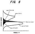
- Fig. 6 is a graph showing a noise density distribution of a received electric signal used for explaining the simulating operation of the optical transmission system and the method for supervising the same, according to the first preferred embodiment.
- Fig. 7 is a graph showing the relation between a received light power and a bit-error rate, used for explaining the simulating operation of the optical transmission system and the method for supervising the same, according to the first preferred embodiment.
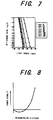
- Fig. 8 is a graph showing the relation between a transmission distance and a power penalty, used for explaining the simulating operation of the optical transmission system and the method for supervising the same, according to the first preferred embodiment.
- Fig. 9 is a table used for explaining the simulating operation of the optical transmission system and the method for supervising the same, according to the first preferred embodiment.
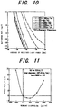
- Fig. 10 is a graph showing the variation of simulated bit-error rate, used for explaining the simulating operation of the optical transmission system and the method for supervising the same, according to the first preferred embodiment.
- Fig. 11 is a graph showing the variation of simulated power penalty, used for explaining the simulating operation of the optical transmission system and the method for supervising the same, according to the first preferred embodiment.
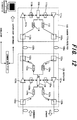
- Fig. 12 is a block diagram showing the structure of an optical transmission system and a method for supervising the same, according to a second preferred embodiment of the invention.
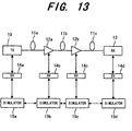
- Fig. 13 is a block diagram showing the structure of an optical transmission system and a method for supervising the same, according to a third preferred embodiment of the invention.
- Fig. 14 is a block diagram showing the structure of an optical transmission system and a method for supervising the same, according to a fourth preferred embodiment of the invention.
- Fig. 15 is a block diagram showing the structure of an optical transmission system and a method for supervising the same, according to a fifth preferred embodiment of the invention.
- Fig. 16 is a block diagram showing the structure of an optical transmission system and a method for supervising the same, according to a sixth preferred embodiment of the invention.
- Fig. 17 is a block diagram showing the structure of an optical transmission system and a method for supervising the same, according to a seventh preferred embodiment of the invention.
- Fig. 18 is a block diagram showing the structure of an optical transmission system and a method for supervising the same, according to an eighth preferred embodiment of the invention.
- Fig. 19 is a block diagram showing the structure of an optical transmission system and a method for supervising the same, according to an eleventh preferred embodiment of the invention.
- Fig. 20 is a block diagram showing the structure of an optical transmission system and a method for supervising the same, according to a twelfth preferred embodiment of the invention.
- Fig. 21 is a block diagram showing the structure of an optical transmission system and a method for supervising the same, according to a thirteenth preferred embodiment of the invention.
- Fig. 22 is a block diagram showing the structure of a dispersion compensator (DC) used in the optical transmission system and the method for supervising the same, according to the thirteenth preferred embodiment.
- DC dispersion compensator
- Fig. 23 is a block diagram showing the structure of an optical transmission system and a method for supervising the same, according to a fourteenth preferred embodiment of the invention.
- Fig. 24 is a graph showing the dependency of the power penalty on the dispersion degree D using a chirp coefficient ⁇ as a parameter, in the optical transmission system and the method for supervising the same, according to the fourteenth preferred embodiment.
- Fig. 25 is a block diagram showing the structure of an optical transmission system and a method for supervising the same, according to a fifteenth preferred embodiment of the invention.
- Fig. 26 is a block diagram showing the structure of an optical transmission system and a method for supervising the same, according to a sixteenth preferred embodiment of the invention.
- Fig. 27 is a graph showing the discrimination characteristic of a frequency discriminator in the optical transmission system and the method for supervising the same, according to the sixteenth preferred embodiment.
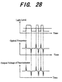
- Fig. 28 is a waveform diagram used for explaining the operation of the optical transmission system and the method for supervising the same, according to the sixteenth preferred embodiment.
- Fig. 29 is a block diagram showing the structure of an optical transmission system and a method for supervising the same, according to a seventeenth preferred embodiment of the invention.
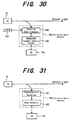
- Fig. 30 is a block diagram showing the detailed structure of an extinction ratio detector in the optical transmission system and the method for supervising the same, according to the seventeenth preferred embodiment.
- Fig. 31 is a block diagram showing the detailed structure of another extinction ratio detector in the optical transmission system and the method for supervising the same, according to the seventeenth preferred embodiment.
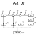
- Fig. 32 is a block diagram showing the structure of an optical transmission system and a method for supervising the same, according to an eighteenth preferred embodiment of the invention.
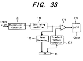
- Fig. 33 is a block diagram showing the detailed structure of an optical receiving device, including a received waveform peak detector, in the optical transmission system and the method for supervising the same, according to the seventeenth preferred embodiment.
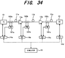
- Fig. 34 is a block diagram showing the structure of an optical transmission system and a method for supervising the same, according to a nineteenth preferred embodiment of the invention.
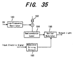
- Fig. 35 is a block diagram showing the detailed structure of an SBS monitor for a transmission line fiber and an optical transmitter controlling the SBS in the optical transmission system and the method for supervising the same, according to the nineteenth preferred embodiment.
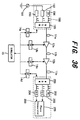
- Fig. 36 is a block diagram showing the structure of an optical transmission system and a method for supervising the same, according to a twentieth preferred embodiment of the invention.
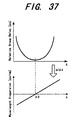
- Fig. 37 is a graph used for explaining the measurement theory of wavelength dispersion in an optical fiber, in the optical transmission system and the method for supervising the same, according to the twentieth preferred embodiment.
- the invention is applicable to an optical communication system, such as a basic trunk transmission system, a subscriber network system, etc.
- Fig. 1 shows the outline of an optical transmission system using an optical transmission simulator, according to a first preferred embodiment of the invention.
- a plurality of EDFAs Erbium-Doped Fiber Amplifier
- EDFAs Erbium-Doped Fiber Amplifier
- the optical transmission system includes an optical transmitter (TX) 10, optical fibers 11a, 11b and 11c, repeaters 12a and 12b, an optical receiver (RX) 13, interface units 14a, 14b, 14c and 14d and an optical simulator 15.
- Each repeater is equipped with an optical amplifier, which amplifies a light signal.
- the optical fiber 11a connects the optical transmitter 10 and the repeater 12a.
- the optical fiber 11b connects repeaters 12a and 12b.
- the optical fiber 11c connects the repeater and the optical receiver 13.
- the interface units 14a, 14b, 14c and 14d are connected to the optical transmitter 10, the repeater 12a, the repeater 12b and the optical receiver 13, respectively.
- Each of the interface units (SV) 14a, 14b, 14c and 14d monitors and controls each device connected thereto.
- the simulator 15 is connected to the interface units 14a, 14b, 14c and 14d with a communication line, such as a telephone line, a supervisory network, etc.
- the simulator 15 simulates the operation of the system based on information from the interface units (SV) 14a, 14b, 14c and 14d.
- the optical transmitter (TX) 10 converts an electric signal into a light signal having a specific wavelength, and transmits it to the repeater 12a via the optical fiber 11a.
- the system may have two alternative system lines of "0 system” and "1 system” including.
- the main system line is usually used, and the other system line is used when a problem happens on the main system line.
- each of the repeaters 12a and 12b is provided with an amplifier, which amplifies a received light signal in analog fashion, and transmits the amplified signal to the following device.
- the interface units 14a, 14b, 14c and 14d are supervisory units, each of which detects estimation parameters from the connected device, and controls the device.
- the simulator 15 is composed of a workstation, application software for simulation, and the like to estimate an error-bit rate or a Q-factor of the system based on the current operating condition of each device.
- the current operating condition is obtained from the estimation parameters.
- the communication line shown by a broken line can be any kind of communication way, besides a telephone line and a supervisory network.
- Deterioration of an SN (Signal to Noise) ratio and waveform of a light signal, transmitted through the optical fibers 11a, 11b and 11c mainly influence transmission quality of the optical transmission system.
- the transmission quality may be influenced by an extinction ratio of the optical transmitter 10, an NF noise Figure) of the optical repeaters 12a and 12b, a Q-factor of the optical receiver 13, a propagation loss of the transmission line 11a, 11b and 11c, a dispersion coefficient and power variation (level-diagram) in the transmission line 11a, 11b and 11c.
- the SN ratio is deteriorated when a low level light signal is received by the repeaters 12a and 12b and the optical receiver 13.
- a waveform of the light signal is deteriorated due to non-linear effect in the transmission lines 11a, 11b and 11c when a power of an input light is too high.
- the level-diagram represents the variation of power levels of the light signal, transmitted through the optical fibers 11a, 11b and 11c and the optical repeaters 12a and 12b, relative to positions on the transmission line, as shown in Fig. 2.
- the above described estimation parameters which are the factors deteriorating the transmission quality, are monitored and controlled to obtain the maximum system margin.
- the system margin can be maximized based on the Q-factor of the optical receiver 13.
- the estimation parameters are actually measured (detected), and the measured values are supplied through the interface units 14a, 14b, 14c and 14d to the simulator 15.
- the simulator 15 estimates the bit-error rate or the Q-factor, in accordance with which the level-diagram of each device and a level discrimination point of the optical receiver 13 are controlled so that the system margin would be the maximum.
- the simulator 15 needs the following parameters to estimate the bit-error rate or the Q-factor:
- the estimation parameters about the optical transmitter 10 include a false random signal number (bit number), a transmission speed, a wavelength of a signal light, an ⁇ parameter and an extinction ratio of an optical modulator, and an SN ratio.
- the estimation parameters about the optical fibers 11a, 11b and 11c include first-order dispersion and second-order dispersion for each wavelength, a non-linear constant, a fiber length, a propagation loss and an input light power.
- the estimation parameters about the optical amplifiers in the repeaters 12a and 12b include a signal gain, an NF (Noise Figure) and an input/output light power.
- the estimation parameters about an optical filter include a transmission bandwidth and an insert loss.
- the optical filter is arranged at an upward side of the optical receiver 13 for removing ASE (Amplified Spontaneous Emission) noise.
- the estimation parameters about the optical receiver 13 include an O/E conversion factor, a receiving bandwidth (electric) and a Q-factor.
- the Q-factor of the received signal at the optical receiver 13 is controlled to be the maximum or the bit-error rate is controlled to be the minimum.
- the simulator 15 may includes a workstation (WS) connected through a supervisory network for example, using a 10BASE-T.
- the Q-factor of an electric signal which is to be discriminated by the optical receiver 13 is defined based on a noise generated in the optical amplifier and waveform deterioration caused by a non-linear effect in the optical fibers.
- the level discrimination point in the optical receiver 13 is optimized when the system is installed.
- the simulator 15 controls each optical amplifier contained in a device to have the optimum output power.
- Fig. 3 shows the outline of the operation of the simulator 15.
- the upper column shows the configuration of the system (system setup)
- the middle column shows calculating operation (calculation)
- the lower column shows input/output data for each device.
- n number of wavelengths, ⁇ 1 to ⁇ n, are multiplexed in the optical fiber 11a passing through an optical amplifier (LA).
- LA optical amplifier
- the light signal When a light signal is transmitted to the optical receiver 13, the light signal is converted into an electric signal by an O/E converter circuit in the optical receiver 13.
- the optical receiver 13 amplifies the electric signal for discrimination and reproduction.
- the estimation parameters such as an O/E conversion efficiency are converted into digital signals by an A/D converter circuit.
- the digital signals are supplied to a CPU, and to the simulator 15 through the interface unit 14d.
- the optical transmitter 10 supplies the estimation parameters of a light wavelength, a signal input power, an optical signal pattern and a chirp level to the simulator 15.
- the simulator 15 performs calculation in accordance with an optical signal sequence, shown in Fig. 4, using the ON/OFF pattern (optical signal pattern) and the chirp level. The calculation sequence will be described later.
- the optical fibers 11a, 11b and 11c supply estimation parameters of a GVD (Group Velocity Delay), an SPM (Self Phase Modulation), an XPM (Xross Phase Modulation) and an FWM (Four Wave Mixing).
- GVD Group Velocity Delay
- SPM Self Phase Modulation
- XPM Xross Phase Modulation
- FWM Frequency Division Multiple Access
- Each optical amplifier supplies estimation parameters of a gain tilt and a distortion, caused by an ASE (Amplified Spontaneous Emission) integration.
- the simulator 15 analyzes a signal waveform in the optical transmission line in accordance with the Split-Step-Fourier scheme.
- the optical fiber amplifiers using an EDFA (Erbium-Doped Fiber Amplifier), a signal quality is estimated based on its gain and ASE noise.
- EDFA Erbium-Doped Fiber Amplifier
- n2 non-linear constant
- Fig. 4 shows the flow of the simulating calculation in the simulator 15.
- input data including the average signal power, optical signal pattern and chirp level are supplied to the simulator 15.
- the following devices are further connected an optical fiber, such as an SMF (Single Mode Fiber); a DSF (Dispersion Shift Fiber); a DCF (Dipersion Compensation Fiber); an EDFA; an optical filter and other devices.
- the simulator 15 Based on the propagation loss of the optical fibers 11a, 11b and 11c, the gain of the optical amplifier (LA) of the EDFA, the gain-tilt and the ASE integration, the simulator 15 performs a predetermined calculation.
- the source data (estimation parameters) and the calculation results are stored in a data file so that the calculation sequence is controlled based on the data file.
- the simulation provides output data of an optical spectrum, a received waveform (eye-pattern) and a BER (bit-Error Fate).
- Figs. 5 to 8 show variation of the bit-error rate and power penalty.
- Fig. 5 shows a waveform of the detected current signal
- Fig. 6 shows noise density distribution of the detected current signal
- Fig. 7 shows the relation between detected light power and the bit-error rate
- Fig. 8 shows variation of power penalty relative to transmission distances.
- the above-described simulating calculation is started with Fig. 5 to Fig. 8 so as to obtain the data shown in Fig. 8.
- the power penalty represents the variation of the detected light power relative to transmission distances, using the reference level of the light power with a distance of zero.
- Figs. 9 to 11 show the contents of real calculation, carried out by the simulator 15.
- Fig. 9 shows specification of the simulating calculation both in the cases of a single channel mode (single wavelength) and a WDM mode.
- Figs. 10 and 11 show characteristics of the bit-error rate and the power penalty, calculated from the simulation under the condition shown in Fig. 9. In the first preferred embodiment, the simulation is carried out for a single channel transmission.
- each of the optical transmitter (TX) 10, the optical transmission line 11, the repeaters 12a and 12b and the optical receiver (RX) 13 supplies the estimation parameters (source data) through the interface units (SV) 14 to the simulator 15.
- the simulator 15 estimates the BER (Bit-Error Rate) or a Q-factor, in accordance with the above-described simulating operation, and controls the level-diagram of each device and the level discrimination point of the optical receiver 13 so that the optical transmission system has the maximum margin (system margin) as a whole.
- the simulator 15 When the optical transmission system is installed, the simulator 15 performs the above-described calculation based on inspected data of each device, so that the future system margin can be estimated. In addition, the simulator 15 can calculate the optimum condition for each device, and control each device based thereon to obtain the maximum system margin at the beginning.
- the optical transmission system and the method for supervising the same according to the first preferred embodiment, estimation parameters that deteriorate transmission quality are detected from each device. And, the simulator 15 simulates a bit-error ratio or a Q-factor, and controls each device so as to minimize the bit-error ratio or to maximize the Q-factor. Therefore, the optical transmission system can have the optimum system margin even when the system has been installed and in operation
- Fig. 12 shows an optical transmission system, which performs automatic detection/control using a supervisory network.
- the system is provided with optical fiber amplifiers of EDFA (Erbium-Doped Fiber Amplifier).
- EDFA Erbium-Doped Fiber Amplifier
- the optical transmission system includes a transmitter/ receiver 110, a repeater 120, a workstation (WS) 130, which automatically collects estimation parameters (source data) from each device to control the devices using the supervisory network.
- WS workstation
- the transmitter/receiver 110 and the repeater 120 are connected with transmission lines 100a and 100b of optical fibers, which transmits both of two main signal lights and a supervisory light.
- the main signal lights are wavelength-multiplexed to be transmitted in the both directions in the optical fibers 100a and 100b.
- the transmitter/receiver 110 includes optical amplifiers 111a and 111b; optical couplers 112a and 112b, which divides a light by wavelengths and directions; an E/O converter 113; an O/E converter 114, interface units (SV) 115a and 115b and a controller 116.
- the optical amplifier 111a is connected to an input terminal of the optical coupler 112a and the interface unit 115a.
- the optical coupler 112a is connected at the other input terminal to the E/O converter 113.
- the controller 116 is connected to the interface unit 115a, the E/O converter 113, the O/E converter 114 and to the interface unit 115b.
- the O/E converter 114 is connected to an output terminal of the optical coupler 112b.
- the optical amplifier 111b is connected to the interface unit 115b and to the other output terminal of the optical coupler 112b.
- an electric signal is converted into a light signal to have a specific wavelength.
- the light signal is supplied to the optical amplifier 111a.
- the light signal with the specific wavelength is received, and is converted into an electric signal.
- the electric signal is divided and supplied to subscribers (not shown), or the like.
- the repeater 120 includes optical amplifiers 121a and 121b; optical couplers 122a, 122b, 122c and 122d, each of which divides a light signal for each wavelength/direction; E/O converters 123a and 123b; O/E converters 124a and 124b; interface units (SV) 125a and 125b and a controller 126.
- the repeater 120 amplifies the received light signal in analog fashion, and also receives/supplies the supervisory signal between the adjacent two transmitter/receivers 110.
- the optical coupler 122a is connected at an input terminal to the optical coupler 112a in the transmitter/receiver 110 though the optical fiber 100a.
- the optical coupler 122a is also connected at output terminals to the optical amplifier 121a and to the O/E converter 124a.
- the optical amplifier 121 is connected to the interface unit 125a and to an output terminal of the optical coupler 122b.
- the optical coupler 122b is connected at the other input terminal to the E/O converter 123b.
- the controller 126 is connected to the O/E converters 124a and 124b, the E/O converters 123a and 123b and to the interface units 125a and 125b.
- the optical coupler 122d is connected at output terminals to the O/E converter 124b and the optical amplifier 121b.
- the optical coupler 122c is connected at input terminals to the E/O converter 123a and the optical amplifier 121b, and at the output terminal to the optical coupler 112b in the transmitter/receiver 110 via the optical fiber 100b.
- the workstation (WS) 130 includes a simulator and monitor/control software, and is provided with a common data file for the estimation parameters, described in the first preferred embodiment.
- the workstation (WS) 130 is connected to the transmitter/receiver 110 and the repeater 120 to supervise the transmission line and each device and to collect the parameters from each device for automatic control of each device via the supervisory network.
- the transmitter/receiver 110 converts an electric signal into a light signal to have a specific wavelength and transmits the light signal to the repeater 120 via the optical fiber 100a.
- the transmitter/receiver 110 also receives a light signal, and converts the light signal into an electric signal to be supplied to subscriber lines.
- the repeater 120 amplifies the received light signal in analog fashion, and also receives/supplies the supervisory signal between the adjacent two transmitter/receivers 110.
- the main signal lights are wavelength-multiplexed to be transmitted in two ways on the optical fibers 100a and 100b.
- the supervisory light transmitted between the transmitter/receiver 110 and the repeater 120, is designed to have a different wavelength from the main signal light, but the same in the whole system.
- the supervisory light is wavelength-multiplexed in the optical fibers 100a and 100b.
- the supervisory light has the single wavelength in the whole system, the supervisory light is transmitted in a single way. In other words, two supervisory lights having the opposite directions never been multiplexed in the same optical fiber.
- the workstation (WS) 130 performs monitor/control operation to each estimation parameter in the upward and downward lines 100a and 100b on a constant cycle.
- the simulator in the workstation (WS) 130 collects the estimation parameters via the common data file to calculate the optimum parameters (control factors).
- each device is arranged in the supervisory network, and the estimation parameters are detected from each device using the supervisory network to control each device automatically. Therefore, the optical transmission system always operates under the optimum condition.
- Fig. 13 shows the outline of an optical transmission system using an optical transmission simulator, according to a third preferred embodiment of the invention.
- the same or corresponding components to the first preferred embodiment are indicated by the same symbols.
- the optical communication system includes an optical transmitter (TX) 10; an optical transmission line, including optical fibers 11a, 11b and 11c; repeaters 12a and 12b; an optical receiver (RX) 13, which receives the light signal; interface units (SV) 14a, 14b, 14c and 14d; and simulators 15a, 15b, 15c and 15d.
- TX optical transmitter
- RX optical receiver
- the optical fiber 11a connects the optical transmitter 10 and the repeater 12a.
- the optical fiber 11b connects the repeaters 12a and 12b.
- the optical fiber 11b connects the repeater 12b and the optical receiver 13.
- the interface unit 14a is connected between the optical transmitter 10 and the simulator 15a.
- the interface unit 14b is connected between the repeater 12a and the simulator 15b.
- the interface unit 14c is connected between the repeater 12b and the simulator 15c.
- the interface unit 14c is connected between the optical receiver 13 and the simulator 15d
- Each of the repeaters 12a and 12b is equipped with an optical amplifier.
- Each of the interface units 14a, 14b, 14c and 14d monitors and controls the connected device.
- Each of the simulators 15a, 15b, 15c and 15d performs simulating operation based on estimation parameters of each device detected by the interface unit (SV).
- the simulators 15a, 15b, 15c and 15d are connected to each other by a communication line, shown by broken lines, such as a telephone line, a supervisory network, etc.
- a workstation is arranged at a location where the optical transmitter (TX) 10 or one of repeaters 12a and 12b is placed.
- Each of the simulators 15a, 15b, 15c and 15d may be established by installing application software, performing the above-mentioned simulation, in the workstation.
- each simulator (workstation) can simulate the operation of the corresponding area in parallel.
- a process time for simulation and control becomes shorter as compared to the system using a single simulator for all the devices.
- Fig. 14 shows the outline of an optical transmission system using an optical transmission simulator, according to a fourth preferred embodiment of the invention.
- the same or corresponding components to the preferred embodiment, shown in Fig. 1, are indicated by the same reference numerals and symbols.
- the optical transmission system includes optical transmitters (TX) 20a and 20b; optical transmission lines including optical fibers 21a, 21b, 21c, 21d, 21e and 21f; repeaters 22a, 22b, 22c and 22d; optical receivers 23a and 23b; interface units (SV) 14a, 14b, 14c and 14d; and a simulator 15.
- TX optical transmitters
- optical transmission lines including optical fibers 21a, 21b, 21c, 21d, 21e and 21f
- repeaters 22a, 22b, 22c and 22d optical receivers 23a and 23b
- interface units (SV) 14a, 14b, 14c and 14d and a simulator 15.
- an upward circuit is formed by the optical transmitter 20a, the repeaters 22a and 22b, the optical fibers 21a, 21b and 21c and the optical receiver 23a.
- a downward circuit is formed by the optical transmitter 20b, the repeaters 22c and 22d, the optical fibers 21d, 21e and 21f and the optical receiver 23b.
- the optical transmitter 20a and the optical receiver 23b are connected to the interface unit 14a.
- the repeaters 22a and 22c are connected to the interface unit 14b
- the repeaters 22b and 22d are connected to the interface unit 14c.
- the optical transmitter 20b and the optical receiver 23a are connected to the interface unit 14d.
- the optical fiber 21a connects the optical transmitter 20a and the repeater 22a.
- the optical fiber 21b connects the repeaters 22a and 22b.
- the optical fiber 21c connects the repeater 22b and the optical receiver 23a.
- the optical fiber 21d connects the optical receiver 23b and the repeater 22c.
- the optical fiber 21e connects the repeaters 22c and 22d.
- the optical fiber 21f connects the repeater 22d and the optical transmitter 20b.
- the optical transmitters 20a and 20b are designed to transmit wavelength-multiplexed light signals
- Each of the repeaters 22a, 22b, 22c and 22d is equipped with an optical amplifier, which amplifies the light signal.
- the optical receivers 23a and 23b are designed to receive the multiplexed light signals.
- Each of the interface units 14a, 14b, 14c and 14d monitors and controls the device that is connected thereto with a communication line, such as a telephone line, a supervisory network, etc.
- the simulator 15 performs simulating operation based on estimation parameters of each device detected by the interface units 14a, 14b, 14c and 14d.
- Each of the optical transmitters 20a and 20b, the repeaters 22a, 22b, 22c and 22d and the optical receivers 23a and 23b is designed to transmit a wavelength-multiplexed light signal.
- the optical fibers 21a, 21b, 21c, 21d, 21e and 21f supervisory signals which is illustrated by broken lines, are wavelength-multiplexed to the main light signal.
- the supervisory signals have a wavelength that is different from the main signal light.
- the supervisory signals have the same wavelength in the whole system, and are multiplexed to one fiber selected from "m" fibers, based on the operating conditions of the optical fibers 21a, 21b, 21c, 21d, 21e and 21f, multiplexers and the repeaters 22a, 22b, 22c and 22d.
- the supervisory lights have the common wavelength in the whole system, the supervisory lights travel in one way. In other words, two supervisory lights traveling in the opposite directions are never multiplexed in the same optical fiber.
- the supervisory lights are wavelength-multiplexed to the main signal light in the optical fibers 21a, 21b, 21c, 21d, 21e and 21f, so that an additional monitor network is not required for monitoring and controlling each device.
- Fig. 15 shows the outline of an optical transmission system using an optical transmission simulator, according to a fifth preferred embodiment of the invention.
- the same or corresponding components to the fourth preferred embodiment, shown in Fig. 14, are indicated by the same reference numerals and symbols.
- the optical transmission system includes an optical transmitter 20, an optical transmission line including optical fibers 21a, 21b and 21c, repeaters 22a and 22b, an optical receiver 23, interface units (SV) 14a, 14b, 14c and 14d and a simulator 15.
- the interface units 14a, 14b, 14c and 14d are connected to the optical transmitter 20, the repeater 22a, the repeater 22b and the optical receiver 23, respectively.
- the interface units 14a, 14b, 14c and 14d are connected to each other by a communication line, such as a telephone line, a supervisory network etc.
- the interface unit 14a is connected to the simulator 15.
- the optical fiber 21a connects the optical transmitter 20 to the repeater 22a.
- the optical fiber 21b connects the repeater 22a to the repeater 22b.
- the optical fiber 21c connects the repeater to the optical receiver 23.
- the optical transmitter 20 transmits wavelength-multiplexed light signals.
- Each of the repeaters 22a and 22b is equipped with an optical amplifier, which amplifies the light signals.
- the optical receiver 23 receives the multiplexed light signals.
- Each of the interface units 14a, 14b, 14c and 14d monitors and controls the device connected thereto.
- the simulator 15 performs simulating operation based on estimation parameters of each device detected by the interface units 14a, 14b, 14c and 14d.
- Fig. 15 an upward way and a downward way are formed by the single transmission line, so that supervisory signals having the different wavelengths are multiplexed in the transmission line (21a, 21b and 21c) to perform a two-way transmission.
- broken lines show the supervisory lights.
- the supervisory signals have the different wavelengths ⁇ 1 and ⁇ 2 between the upward and downward ways, so that each device can be monitored and controlled using the single transmission line.
- Fig. 16 shows the outline of an optical transmission system using an optical transmission simulator, according to a sixth preferred embodiment of the invention.
- the same or corresponding components to the first preferred embodiment, shown in Fig. 1, are indicated by the same reference numerals and symbols.
- the optical transmission system includes optical transmitters 30 and 31, a WDM (Wavelength Division Multiplexer) 32 at a transmitter side; an optical transmission line including optical fibers 11a, 11b and 11c, repeaters 12a and 12b, a WDM 33 at a receiver side, optical receivers 34 and 35, interface units (SV) 14a, 14b, 14c and 14d, and a simulator 15.
- the interface unit 14a is connected to the optical transmitters 30 and 31 and the WDM 32.
- the interface units 14b and 14c are connected to the repeaters 12a and 12b, respectively.
- the interface unit 14d is connected to the optical receivers 34 and 35 and the WDM 33.
- Each of the interface units 14a, 14b, 14c and 14d is connected to the simulator 15 by a communication line, such as a telephone line, a supervisory network, etc.
- the optical transmitters 30 and 31 transmit different wavelengths of light signals.
- Each of the repeaters 12a and 12b is equipped with an optical amplifier, which amplifies the light signals.
- the optical receivers 34 and 35 receive the light signals having the different wavelengths.
- Each of the interface units 14a, 14b, 14c and 14d monitors and controls the device that is connected thereto.
- the simulator 15 performs simulating operation based on estimation parameters of each device detected by the interface units 14a, 14b, 14c and 14d.
- the WDM 32 at the transmitter side is designed to multiplex light signals supplied from the transmitters 30 and 31 and transmit the multiplexed light signal to the optical fiber 11a.
- the WDM 33 at the receiver side is designed to divide the multiplexed light signal supplied from the optical fiber 11c and supply the divided light signals to the optical receivers 34 and 35.
- levels of an output signal of the amplifier is varied from wavelength to wavelength.
- the variation of the light level changes non-linear effect and SN ratio in the optical fiber, therefore, the light level has to be controlled to have the optimum level for each wavelength. In other words, it is required that the margin defined by the non-linear effect and SN ratio, is controlled to have the maximum value.
- the optical transmitters 30 and 31 and the optical receivers 34 and 35 are connected through the interface units (SV) 14a, 14b, 14c and 14d to the simulator 15.
- the characteristics of each device are detected and transmitted via the interface units (SV) 14a, 14b, 14c and 14d to the simulator 15.
- the simulator 15 estimates (calculates) the bit-error rate or Q-factor, and controls the level-diagram of each wavelength and the level discrimination point of the optical receivers 34 and 35 so as to obtain the maximum system margin.
- This preferred embodiment can be used when another wavelength channel is added to the optical transmission system of the first preferred embodiment.
- the system can be controlled to operate under the optimum condition automatically.
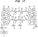
- Fig. 17 shows an optical transmission system using an optical transmission simulator, according to a seventh preferred embodiment of the invention.
- the same or corresponding components to shown in Figs. 14 and 16 are indicated by the same reference numerals and symbols.
- the seventh preferred embodiment is designed by applying the optical transmission simulator of the sixth preferred embodiment to the wavelength-multiplex system, transmitting light signals having the different wavelengths.
- the optical transmission system includes an upward transmission circuit, a downward transmission circuit, interface units 14a, 14b, 14c and 14d and a simulator 15.
- the upward transmission circuit includes optical transmitters 30a and 31a, a WDM (Wavelength Division Multiplexer) 32a; an optical transmission line including optical fibers 21a, 21b and 21c, repeaters 22a and 22b, a WDM 33a at a receiver side and optical receivers 34a and 35a.
- WDM Widelength Division Multiplexer
- the downward transmission circuit includes optical transmitters 30b and 31b, a WDM (Wavelength Division Multiplexer) 33b; an optical transmission line including optical fibers 21d, 21e and 21f, repeaters 22c and 22d, a WDM 32b at a receiver side and optical receivers 34b and 35b.
- WDM Widelength Division Multiplexer
- the interface unit 14a is connected to the optical transmitters 30a and 31a, WDMs 32a and 32b and the optical receivers 34b and 35b.
- the interface unit 14b is connected to the repeaters 22a and 22c.
- the interface unit 14c is connected to the repeaters 22b and 22d.
- the interface unit 14d is connected to the optical transmitters 30b and 31b, WDMs 33a and 33b and the optical receivers 34a and 35a.
- the interface unit 14a is connected to the simulator 15.
- the optical transmitters 30a, 31a, 30b and 31b transmit different wavelengths of light signals.
- Each of the repeaters 22a, 22b, 22c and 22d is equipped with an optical amplifier, which amplifies the light signals.
- the optical receivers 34a, 35a, 34b and 35b receive the light signals having the different wavelengths.
- Each of the interface units 14a, 14b, 14c and 14d monitors and controls the device that is connected thereto.
- the simulator 15 performs simulating operation based on estimation parameters of each device detected by the interface units 14a, 14b, 14c and 14d.
- the WDMs 32a and 33b at the transmitter side are designed to multiplex light signals supplied from the transmitters 30a and 31a, and 30b and 31b, respectively.
- the WDMs 33a and 32b at the receiver side are designed to divide the multiplexed light signal supplied from the optical fiber 21c and 21d, respectively.
- a supervisory signal, shown by a broken line, is wavelength-multiplexed in the optical fibers 21a, 21b, 21c, 21d, 21e and 21f.
- the supervisory signal is transmitted using wavelength-multiplexing technique, so that each device can be monitored and controlled without a supervisory network.
- Fig. 18 shows an optical transmission system using an optical transmission simulator, according to an eighth preferred embodiment of the invention.
- the same or corresponding components to the sixth and seventh preferred embodiments shown in Figs. 16 and 17 are indicated by the same reference numerals and symbols.
- the optical transmission system includes optical transmitters 30 and 31, a WDM (Wavelength Division Multiplexer) 32 at a transmitter side; an optical transmission line including optical fibers 21a, 21b and 21c, repeaters 12a and 12b, a WDM 33 at a receiver side, optical receivers 34 and 35, interface units (SV) 14a, 14b, 14c and 14d, and a simulator 15.
- the interface unit 14a is connected to the optical transmitters 30 and 31, and to the simulator 15.
- the interface units 14b and 14c are connected to the repeaters 12a and 12b, respectively.
- the interface unit 14d is connected to the optical receivers 34 and 35.
- the interface units 14a, 14b, 14c and 14d are connected to each other by a communication line, such as a telephone line, a supervisory network, etc.
- the optical transmitters 30 and 31 transmit different wavelengths of light signals.
- Each of the repeaters 12a and 12b is equipped with an optical amplifier, which amplifies the light signals.
- the optical receivers 34 and 35 receive the light signals having the different wavelengths.
- Each of the interface units 14a, 14b, 14c and 14d monitors and controls the device that is connected thereto.
- the simulator 15 performs simulating operation based on estimation parameters of each device detected by the interface units 14a, 14b, 14c and 14d.
- the WDM 32 at the transmitter side is designed to multiplex light signals supplied from the transmitters 30 and 31 and transmit the multiplexed light signal to the optical fiber 21a.
- the WDM 33 at the receiver side is designed to divide the multiplexed light signal supplied from the optical fiber 21c and to supply the divided light signals to the optical receivers 34 and 35.
- supervisory signal lights having the different wavelengths ⁇ 1 and ⁇ 2 in upward and downward directions, are transmitted over the common transmission line by two-way transmission using the wavelength multiplexing technique. Therefore, each device can be monitored and controlled using the single transmission line.
- wavelength multiplexing technique such as shown in Fig. 18, when the number of wavelength channels are increased, for example, another optical transmitter (TX) for a different wavelength is added to the system, output levels of the other wavelength channels may be changed and a reciprocal action (four-wave-mixing, cross-talk or the like) may occur.
- TX optical transmitter
- a reciprocal action four-wave-mixing, cross-talk or the like
- the simulator 15 estimates a bit-error rate or a Q-factor, and controls an output level of each device and a discrimination point of the optical receiver so that the system has the maximum margin.
- each device can be automatically controlled so that the system operates under the optimum condition.
- output levels of the other wavelength channels may be changed and a reciprocal action (four-wave-mixing, cross-talk or the like) may occur.
- the simulator 15 estimates a bit-error rate or a Q-factor, and controls an output level of each device and a discrimination point of the optical receiver so that the system has the maximum margin.
- each device can be automatically controlled so that the system operates under the optimum condition.
- Fig. 19 shows the outline of an optical transmission system using an optical transmission simulator, according to an eleventh preferred embodiment of the invention.
- the same or corresponding components to the first preferred embodiment, shown in Fig. 1, are indicated by the same reference numerals and symbols.
- the optical transmission system includes optical transmitters 40 and 41, a first optical transmission line including optical fibers 42a, 42b and 42c, a second optical transmission line including optical fibers 43a, 43b and 43c, repeaters 44a, 44b, 45a and 45b, optical receivers 46 and 47, interface units (SV) 14a, 14b, 14c and 14d, and a simulator 15.
- a first optical transmission line including optical fibers 42a, 42b and 42c
- a second optical transmission line including optical fibers 43a, 43b and 43c
- repeaters 44a, 44b, 45a and 45b optical receivers 46 and 47
- interface units (SV) 14a, 14b, 14c and 14d and a simulator 15.
- the interface unit 14a is connected to the optical transmitters 30 and 31.
- the interface unit 14b is connected to the repeaters 44a and 45a.
- the interface unit 14c is connected to the repeaters 44b and 45b.
- the interface unit 14d is connected to the optical receivers 46 and 47.
- the simulator 15 and the interface units 14a, 14b, 14c and 14d are connected to each other by a communication line, such as a telephone line, a supervisory network, etc.
- the optical transmitters 40 and 41 transmit different wavelengths of light signals.
- Each of the repeaters 44a, 44b, 45a and 45b is equipped with an optical amplifier, which amplifies the light signals.
- the optical receivers 46 and 47 receive the light signals having the different wavelengths.
- Each of the interface units 14a, 14b, 14c and 14d monitors and controls the devices that are connected thereto.
- the simulator 15 performs simulating operation based on estimation parameters of each device detected by the interface units 14a, 14b, 14c and 14d.
- the system of this embodiment includes a pair of optical transmitters (40 and 41), a pair of optical repeaters (44a-44b and 45a-45b) and a pair of optical receivers (46 and 47).
- a first transmission circuit may be formed by the optical transmitter (TX1) 40, the optical fibers 42a and 42b, the repeaters 44a and 44b, and the optical receiver (RX1) 46.
- a second transmission circuit may be formed by the optical transmitter (TX1) 40, the optical fibers 42a and 42b, the repeaters 44a and 44b, and the optical receiver (RX1) 46.
- the devices (40-47) can be selected to form a suitable combination of transmission circuit.
- the system margin generally depends on an extinction ratio of the optical transmitter, an NF (Noise Figure) of the optical repeater, a Q-factor of the optical receiver, and so on.
- the devices (40-47) can be selected to form a suitable combination of transmission circuit in this embodiment, the system margin can be optimized easily even if some devices do not work well.
- the transmission system can be controlled to have an allowable system margin by selecting an optical transmitter having a preferable extinction ratio.
- each device can not have an enough margin, although the system margin may be in the allowable range. Consequently, to obtain a preferable system margin totally, the average of the margin for the devices should be constant.
- the simulator 15 selects the combination of devices, forming the transmission system, so as to obtain the maximum system margin in total. As a result, it is possible to secure a large range of system margin in total.
- Fig. 20 shows the outline of an optical transmission system using an optical transmission simulator, according to a twelfth preferred embodiment of the invention.
- the same or corresponding components to the eleventh preferred embodiment, shown in Fig. 19, are indicated by the same reference numerals and symbols.
- the optical transmission system includes optical transmitters 40 and 41, a WDM (Wavelength Division Multiplexer) 50 at a transmitter side; an optical transmission line including optical fibers 42a, 42b and 42c, repeaters 44a and 44b, optical switches or optical tunable filters 51 and 52; optical receivers 46 and 47, interface units (SV) 14a, 14b, 14c and 14d, and a simulator 15.
- WDM Widelength Division Multiplexer
- the interface unit 14a is connected to the optical transmitters 40 and 41, and to the simulator 15.
- the interface units 14b and 14c are connected to the repeaters 44a and 44b, respectively.
- the interface unit 14d is connected to the optical switches (optical tunable filters) 51 and 52 and to the optical receivers 46 and 47.
- the interface units 14a, 14b, 14c and 14d are connected to each other by a communication line, such as a telephone line, a supervisory network, etc.
- the optical transmitters 40 and 41 transmit different wavelengths of light signals.
- Each of the repeaters 44a and 44b is equipped with an optical amplifier, which amplifies the light signals.
- the optical receivers 46 and 47 receive the light signals having the different wavelengths.
- Each of the interface units 14a, 14b, 14c and 14d monitors and controls the device(s) that is (are) connected thereto.
- the simulator 15 performs simulating operation based on estimation parameters of each device detected by the interface units 14a, 14b, 14c and 14d.
- the WDM 50 is designed to multiplex light signals supplied from the transmitters 40 and 41 and transmit the multiplexed light signal to the optical fiber 42a.
- Each of the optical switches (or optical tunable filters) 51 and 52 is designed to switch a light signal supplied from the optical fiber 42c.
- the interface unit 14d controls the optical switches (or optical tunable filters) 51 and 52 and the optical receivers (RX1 and RX2) 46 and 47 to switch them selectively.
- the light signal supplied from the optical transmitters (TX1 and TX2)40 and 41 are multiplexed by the WDM 50, then transmitted via the optical fiber 42a and the repeaters 44a and 44b to the optical switches (or optical tunable filters) 51 and 52.
- the transmitted light signal is selectively supplied to one of the optical receivers (RX1 and RX2) 46 and 47.
- each device is selected and controlled by using the optical switches (or optical tunable filters) 51 and 52, so that necessary components (devices) can be automatically selected and combined to establish the suitable network that provides the maximum system margin in total.
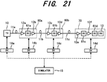
- Fig. 21 shows the outline of an optical transmission system using an optical transmission simulator, according to a thirteenth preferred embodiment of the invention.
- the same or corresponding components to the first preferred embodiment, shown in Fig. 1, are indicated by the same reference numerals and symbols.
- the optical communication system includes an optical transmitter (TX) 10; an optical transmission line, including optical fibers 11a, 11b and 11c; repeater units 60a and 60b; an optical receiver unit 70; interface units (SV) 14a, 14b, 14c and 14d; and a simulator.
- TX optical transmitter
- SV simulators
- Each device is supervised via the simulators (SV) 14a, 14b, 14c and 14d based on the calculation of the simulator 15.
- the optical fiber 11a connects the optical transmitter 10 to the repeater unit 60a.
- the optical fiber 11b connects the repeater units 60a and 60b to each other.
- the optical fiber 11b connects the repeater unit 60b to the optical receiver unit 70.
- the interface units 14a, 14b, 14c and 14d are respectively connected to the optical transmitter 10, the repeater unit 60a, the repeater unit 60b and the optical receiver unit 70.
- the repeater unit 60a includes optical amplifiers 12a and 12b, and a DC (Dispersion Compensator) 61a, connected between the optical amplifiers 12a and 12b.
- the repeater unit 60b includes optical amplifiers 12c and 12d, and a DC (Dispersion Compensator) 61b, connected between the optical amplifiers 12c and 12d.
- the optical receiver unit 70 includes optical amplifiers 12e and 12f, an optical receiver (RX) 13 and dispersion compensators 61c and 61d.
- the dispersion compensator 61c is connected between the optical amplifiers 12e and 12f
- the dispersion compensator 61d is connected between the optical amplifiers 12f and the optical receiver 13.
- Each of the interface units 14a, 14b, 14c and 14d monitors and controls the device connected thereto.
- the simulator 15 performs simulating operation based on estimation parameters of each device detected by the interface units (SV) 14a, 14b, 14c and 14d.
- the interface units 14a, 14b, 14c and 14d and the simulator 15 are connected to each other by a communication line, shown by broken lines, such as a telephone line, a supervisory network etc.
- the optical transmitter 10 transmits a wavelength-multiplexed light signal.
- Each of the dispersion compensators 61a, 61b, 61c and 61d is designed to compensate wavelength distribution of the optical fibers.
- the simulator 15 controls each compensator via the interface unit.
- the optical amplifiers 12e and 12f amplify the light signal supplied from the optical transmitter 10.
- Each of the dispersion compensators (DC) 61c and 61d compensates transmission loss in the optical fibers 11a, 11b and 11c and in the dispersion compensators 61a and 61b.
- the optical transmission system of this embodiment is established by adding the dispersion compensators (DC) 61a, 61b, 61c and 61d, which compensate wavelength dispersion in the optical fibers 11a, 11b and 11c, to the optical repeater and optical receiver (RX) 13 of the first preferred embodiment, shown in Fig. 1.
- each of the dispersion compensators (DC) 61a, 61b, 61c and 61d is built-in each optical amplifier of the optical repeaters 60a and 60b, and the optical receiver unit (RX) 70.
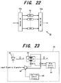
- Fig. 22 shows the structure of the dispersion compensator (DC) 61a.
- the other DCs 61b, 61c and 61d have the same structure as the DC 61a.
- the dispersion compensator (DC) 61a is composed of a plurality of dispersion compensator elements 62 (DC1, DC2, ..., DCN) and optical switches 63a and 63b, which selects one of the dispersion compensator elements 62 (DC1, DC2, ..., DCN).
- a transmission line fiber two kinds of fibers are used.
- One of them is a DSF (Dispersion Shift Fiber) having a wavelength dispersion of around zero ( ⁇ 3.5ps/nm/km) at a wavelength of 1.55 ⁇ m
- the other one is an SMF (Single Mode Fiber) having a larger wavelength dispersion (16 to 20ps/nm/km) at a wavelength of 1.55 ⁇ m.
- the SMFs Single Mode Fiber
- a dispersion compensator is usually used for compensating wavelength dispersion of the fiber.
- the dispersion compensators (DC) 61a, 61b, 61c and 61d shown in Fig. 21, can be controlled via the interface units (SV) 14a, 14b, 14c and 14d, so that the dispersion of each optical fiber can always be compensated under the optimum condition.
- the optical switches 63a and 63b select one of the dispersion compensator elements 62 (DC1, DC2, ..., DCN).
- a PLC Planar Lightwave Circuit
- the compensation rate of each dispersion compensator (DC) is controlled via the interface units (SV) 14a, 14b, 14c and 14d based on the calculation result of the simulator 15.
- SV interface units
- This embodiment is also useful for an optical transmission system using DSF type of optical fibers, because the DSF has variation of wavelength dispersion around zero level. In other words, it is possible to obtain the maximum system margin when the compensation rates of the dispersion compensators are controlled properly.
- Fig. 23 shows the structure of an optical transmitter 80 in an optical transmission system using an optical transmission simulator, according to a fourteenth preferred embodiment of the invention.
- This embodiment is established by adding a function for controlling a chirp parameter (showing variation of wavelength of a light source) to the optical transmission system according to the first preferred embodiment shown in Fig. 1, or the eighth preferred embodiment shown in Fig. 18.
- the detail of the controlling operation has been described, for instance, in the report of "High-speed, low power optical modulator with adjustable chirp parameter," by S. K Korotky et al, Integrated Photonics Research 1991, TuG2, pp.53-54.
- the fourteenth embodiment will be described in accordance with this publication.
- the optical transmitter includes a semiconductor laser 81 as a light source, an optical modulator 82, an optical modulator driving circuit 83, a bias control circuit 84 and an output amplitude control circuit 85.
- the semiconductor laser 81 such as a DFB laser (Distributed Feedback Laser), supplies a light signal having a specific wavelength.
- the optical modulator 82 is of a Mach-Zehnder type, which amplitude-modulates a light supplied from the semiconductor laser 81.
- the optical modulator driving circuit 83 drives the optical modulator 82.
- the optical modulator driving circuit 83 is supplied with an input electric signal to generate output signals having the opposite logical levels to be supplied to electrodes of the optical modulator 82.
- the bias control circuit 84 controls a bias voltage to be applied to each electrode of the optical modulator 82.
- the output amplitude control circuit 85 independently controls the amplitudes of modulating waves to be supplied to the electrodes of the optical modulator 82.
- a wavelength chirp level can be controlled by an outside circuit.
- Fig. 24 shows the variation of power penalty relative to the variation of dispersion "D" for each condition of chirp parameter ⁇ .
- the dispersion D is increased due to a widened waveform and the power penalty is increased as well in general.
- the chirp parameter ⁇ is controlled to meet the condition of ⁇ ⁇ 0, the waveform is narrowed to make the power penalty lower.
- the dispersion D becomes D ⁇ 0, the waveform is narrowed by influences both of the dispersion of the transmission line and the chirp parameter, so that the power penalty is increased rapidly.
- the chirp parameter ⁇ of the optical transmitter 80 is controlled by the outside circuit so as to optimize the waveform of the received signal.
- an output light of the semiconductor laser 81 is supplied to the optical modulator 82 and is modulated in amplitude.
- the optical modulator 82 of Mach-Zehnder type controls the phases of the divided two light signals with a voltage to change degree of interference so that the amplitude modulation is performed.
- the optical modulator 82 is supplied at the electrodes with the output signals of the optical modulator driving circuit 83, which has the opposite logical characteristics, so that the amplitude of each signal is controlled by the output amplitude control circuit 85.
- the bias control circuit 84 controls a bias voltage applied to each electrode of the optical modulator 82.
- the chirp parameter ⁇ is well controlled.
- the chirp parameter of the semiconductor laser 81 is controlled to optimize the waveform of the received signal, and therefore, the maximum system margin is obtained.
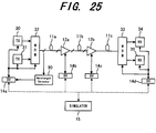
- Fig. 25 shows the outline of an optical transmission system using an optical transmission simulator, according to a fifteenth preferred embodiment of the invention.
- the same or corresponding components to the sixth preferred embodiment, shown in Fig. 16, are indicated by the same reference numerals and symbols.
- the optical transmission system includes optical transmitters 30 and 31, a WDM (Wavelength Division Multiplexer) 32 at a transmitter side; an optical transmission line, including optical fibers 11a, 11b and 11c, repeaters 12a and 12b, a WDM 33 at a receiver side, optical receivers 34 and 35, interface units (SV) 14a, 14b, 14c and 14d; a simulator 15; and a wavelength detector 90.
- WDM Widelength Division Multiplexer
- the interface unit 14a is connected to the optical transmitters 30 and 31, the WDM 32 and the wavelength detector 90.
- the interface units 14b and 14c are connected to the repeaters 12a and 12b, respectively.
- the interface unit 14d is connected to the optical receivers 34 and 35 and the WDM 33.
- Each of the interface units 14a, 14b, 14c and 14d is connected to the simulator 15 by a communication line, such as a telephone line, a supervisory network, etc.
- the optical transmitters 30 and 31 transmit different wavelengths of light signals.
- Each of the repeaters 12a and 12b is equipped with an optical amplifier, which amplifies the light signals.
- the optical receivers 34 and 35 receive the light signals having the different wavelengths.
- Each of the interface units 14a, 14b, 14c and 14d monitors and controls the device that is connected thereto.
- the simulator 15 performs simulating operation based on estimation parameters of each device detected by the interface units 14a, 14b, 14c and 14d.
- the wavelength detector 90 detects and collects the wavelength of each signal transmitted through the optical fiber 11a.
- the WDM 32 at the transmitter side is designed to multiplex light signals supplied from the transmitters 30 and 31 and to transmit the multiplexed light signal to the optical fiber 11a.
- the WDM 33 at the receiver side is designed to divide the multiplexed light signal supplied from the optical fiber 11c and supply the divided light signals to the optical receivers 34 and 35.
- the optical transmission system of this embodiment is formed by adding the wavelength detector 90, which measures the light spectrum of a transmitted light and detects its wavelength, to the above mentioned optical transmission system, shown in Fig. 16. Output data of the wavelength detector 90 are collected by the simulator 15 via the interface unit (SV) 14a.
- the transmission side WDM 32 is designed to control the wavelengths of signals supplied from the transmitters (TX) 30 and 31.
- the wavelengths of signals to be transmitted through the same optical fiber so that an undesirable wavelength of signal does not enter into the wavelength of the main signal.
- the four-wave-mixing phenomenon may occurs, because the wavelengths of the transmission signals are later changed to ensure a high system margin and/or the wavelengths may be changed with time after the installation of the system.
- the wavelength detector 90 detects the wavelengths of the transmission lights, and the detected data are supplied to the simulator 15 via the interface unit 14a.
- the simulator 15 calculates condition of the wavelengths of the signal lights so as not to generate the four-wave-mixing. In response to the calculation result, the simulator 15 controls wavelengths of lights traveling through the optical fibers 11a, 11b and 11c.
- the wavelength detector 90 detects and collects the wavelength of each signal.
- the detected data are supplied to the simulator 15 via the interface unit 14a.
- the simulator 15 calculates a wavelength that does not generate the four-wave-mixing, and controls the wavelength of each transmission signal to approximate to the calculated optimum wavelength. Therefore, even if the wavelengths of the signal lights are changed after the installation of the system, the maximum system margin can be obtained.
- Fig. 26 shows the structure of an optical transmission system using an optical transmission simulator, according to a sixteenth preferred embodiment of the invention.
- the same or corresponding components to the first preferred embodiment, shown in Fig. 1, are indicated by the same reference numerals and symbols.
- Modifying the above mentioned optical transmission system of the first preferred embodiment forms this preferred embodiment, in which a wavelength chirp level of an optical transmitter is monitored.
- the wavelength chirp level corresponds to variation of the light frequency, hereinafter, the chirp level is referred to as the light frequency variation for easier understanding.
- a reference numeral 140 indicates an optical coupler, which divides an output signal of an optical transmitter 10; a reference numeral 141 indicates an optical frequency discriminator; and a reference numeral 142 indicates a peak detector, the output of which is supplied to an interface unit SV (not shown).
- the optical coupler 140 divides the output light of the optical transmitter 10 based on its wavelength and direction, and supplies the divided signal to an optical fiber and to the optical frequency discriminator 141.
- the optical frequency discriminator 141 may be formed by a Mach-Zehnder interferometer, which has the discrimination characteristic, shown in Fig. 27. As shown in Fig. 27, the output power varies in response to the optical frequency of a signal light, so that the frequency of the light can be discriminated from the peak voltage.
- the peak detector 142 detects the peak of the output signal of the optical frequency discriminator 141 and supplies the detected value to the interface unit (SV) as the peak value of the frequency variation.
- the output light from the optical transmitter 10 is divided by the optical coupler 140 into two lights, one of which is supplied to the optical fiber 11 and the other one is supplied to the optical frequency discriminator 141.
- the optical frequency discriminator 141 performs frequency discrimination to the input light in accordance with the discrimination characteristic, shown in Fig. 27.
- the output voltage of the optical frequency discriminator 141 is supplied via the peak detector 142 to the interface unit (SV).
- Fig. 28 shows waveform diagrams, used for describing the operation of this embodiment.
- the graph shows an optical frequency of the input signal and the output voltage of the optical frequency discriminator relative to a pulse waveform of the input signal.
- the optical frequency when the chirp parameter ⁇ is greater than zero ( ⁇ >0), the optical frequency changes in the opposite polarities (codes) as diIferentiated pulses at points where the level of the pulse waveform starts rising up and falling down, as shown in Fig. 28.
- the frequency discriminator 141 supplies an output signal having a pulse waveform that is almost proportional to the variation of the optical frequency.
- the peak detector 142 detects the peak point of the output waveform of the frequency discriminator 141, so that the peak value of the frequency variation of the transmitted light signal.
- an optical pulse waveform is formed in response to the variation of the optical frequency as a phase variation.
- actually detecting the frequency variation is equivalent to calculating the frequency variation from the chirp parameter ⁇ and the optical pulse waveform.
- the frequency variation can be monitored more precisely by the actual detection.
- the chirp parameter can be monitored.
- the chirp quantity which correlates to the frequency variation, is monitored via the interface unit (SV) 14.
- the chirp parameter is monitored by monitoring the frequency variation based on the waveform of the output light supplied from the optical transmitter 10. Therefore, the simulator 15 can calculate (estimate) an error rate and a bit-error rate of the optical receiver in accordance with the chirp parameter.
- Fig. 29 is a diagram showing the structure of an optical transmission system using an optical transmission simulator, according to a seventeenth preferred embodiment of the invention.
- the same or corresponding components to the first preferred embodiment, shown in Fig. 1, are indicated by the same reference numerals and symbols.
- Modifying the above mentioned optical transmission system of the first preferred embodiment, shown in Fig. 1, forms this preferred embodiment, in which an extinction ratio of an optical transmitter is detected and monitored
- the extinction ratio represents a ratio between light levels in non-emission condition and an emission condition.
- the optical transmission system includes an optical transmitter (TX) 10, optical fibers 11a, 11b and 11c, repeaters 12a and 12b, an optical receiver (RX) 13, interface units 14a, 14b, 14c and 14d, an optical simulator 15 and an extinction ratio detector 150.
- TX optical transmitter
- RX optical receiver
- interface units 14a, 14b, 14c and 14d interface units 14a, 14b, 14c and 14d
- an optical simulator 15 an extinction ratio detector 150.
- Each of the repeaters 12a and 12b is equipped with an optical amplifier, which amplifies a light signal.
- the optical fiber 11a connects the optical transmitter 10 and the repeater 12a.
- the optical fiber 11b connects repeaters 12a and 12b.
- the optical fiber 11c connects the repeater and the optical receiver 13.
- the interface units 14a, 14b, 14c and 14d are connected to the extinction ratio detector 150, the repeater 12a, the repeater 12b and the optical receiver 13, respectively.
- Each of the interface units (SV) 14a, 14b, 14c and 14d monitors and controls each device connected thereto.
- the simulator 15 is connected to the interface units 14a, 14b, 14c and 14d with a communication line, such as a telephone line, a supervisory network, etc.
- the simulator 15 simulates the operation of the system based on information from the interface units (SV) 14a, 14b, 14c and 14d.
- the optical transmitter (TX) 10 converts an electric signal into a light signal having a specific wavelength, and transmits it to the repeater 12a via the optical fiber 11a.
- Fig. 30 is a block diagram illustrating the detailed structure of the above-mentioned extinction ratio detector 150.
- the extinction ratio detector 150 includes a sampling oscilloscope, provided with an O/E converter; and a processor 153, which detects an extinction ratio using automatic detecting program.
- the sampling oscilloscope 152 is supplied with a divided dock signal (f0/N), generated in the optical transmitter 10, as a trigger in order to receive a part of the output light supplied from the optical transmitter 10.
- the processor 153 is connected to the interface unit 14a.
- the sampling oscilloscope 152 and the processor 153 form the extinction ratio detector 150 as a whole to supply the detected extinction ratio to the interface unit (SV) 14a.
- each device is supervised via the interface unit (SV) 14a (14b, 14c and 14d) in accordance with the calculation result of the simulator 15.
- the extinction ratio detector 150 detects and monitors the extinction ratio of the waveform of the output signal light supplied from the optical transmitter 10.
- the O/E converter converts the received light signal into a corresponding electric signal to be supplied to the automatic detecting program processor 153.
- the automatic detecting program processor 153 detects an extinction ratio of the output light signal at regular intervals in accordance with the automatic detecting program, and supplies the extinction ratio to the interface unit (SV) 14.
- the extinction ratio detector 150 measures the average (A) of light levels in an emission mode and the average (B) of light levels in a non-mission mode.
- the detecting operation of the sampling oscilloscope 152 is carried out in accordance with the automatic detecting program, which is easily formed from conventional application software.
- extinction ratio detector 150 In stead of the extinction ratio detector 150, another type of extinction ratio detector 160, shown in Fig. 31, can be used.
- Fig. 31 is a block diagram showing the detailed structure of the extinction ratio detector 160.
- the extinction ratio detector 160 includes a photoelectric (O/E) converter 161 and a peak detector 162, in stead of the sampling oscilloscope 152 and the processor 153, used in the extinction ratio detector 150.
- the peak detector 162 can have the same structure as the peak detector shown in Fig. 26.
- the extinction ratio detector 160 In the extinction ratio detector 160, a high level point (A) and a low level (B) of an output light signal supplied from the optical transmitter 10 to detect an extinction ratio thereof.
- the extinction ratio detector 160 can detect the extinction ratio easily as compared to the unit 150, shown in Fig. 30.
- the extinction ratio which is one parameter of calculation in the simulator 15, is monitored via the interface unit (SV) 14a.
- other parameters influencing deterioration of the transmission quality can be controlled to minimize an bit-error rate or to maximize a Q-factor to obtain the maximum system margin.
- Fig. 32 shows the structure of an optical transmission system using an optical transmission simulator, according to an eighteenth preferred embodiment of the invention.
- the same or corresponding components to the first preferred embodiment, shown in Fig. 1, are indicated by the same reference numerals and symbols.
- This preferred embodiment is formed by modifying the above mentioned optical transmission system of the first preferred embodiment, shown in Fig. 1.
- a peak of a light signal received by an optical receiver is detected and monitored.
- the optical transmission system includes an optical transmitter (TX) 10, optical fibers 11a, 11b and 11c, repeaters 12a and 12b, an optical receiver (RX) 13, interface units 14a, 14b, 14c and 14d, an optical simulator 15 and a peak detector 170.
- TX optical transmitter
- RX optical receiver
- Each of the repeaters 12a and 12b is equipped with an optical amplifier, which amplifies a light signal.
- the optical fiber 11a connects the optical transmitter 10 and the repeater 12a.
- the optical fiber 11b connects repeaters 12a and 12b.
- the optical fiber 11c connects the repeater and the optical receiver 13.
- the interface units 14a, 14b, 14c and 14d are connected to the optical transmitter 10, the repeater 12a, the repeater 12b and the optical receiver 13, respectively.
- Each of the interface units (SV) 14a, 14b, 14c and 14d monitors and controls each device connected thereto.
- the simulator 15 is connected to the interface units 14a, 14b, 14c and 14d with a communication line, such as a telephone line, a supervisory network etc.
- the simulator 15 simulates the operation of the system based on information from the interface units (SV) 14a, 14b, 14c and 14d.
- the optical transmitter (TX) 10 converts an electric signal into a light signal having a specific wavelength, and transmits it to the repeater 12a via the optical fiber 11a.
- the peak detector 170 detects a peak of a signal light received by the optical receiver 13.
- the peak detector 170 supplies its output signal to the interface unit (SV) 14d.
- Fig. 33 is a block diagram illustrating the detailed structure of the above-mentioned peak detector 170.
- the peak detector 170 includes a photoelectric (O/E) converter 171; an equalizing amplifier 172; a threshold voltage generator 173; a level discriminator 174; and a D flip-flop (D-FF).
- the photoelectric converter 171 is connected to the equalizing amplifier 172, connected to the peak detector 170.
- the level discriminator 174 is connected at input terminals to the equalizing amplifier 172 and the threshold voltage generator 173, and at an output terminal to the D flip-flop 175.
- the peak detector 170 and the threshold voltage generator 173 are connected to the interface unit 14d.
- the photoelectric (O/E) converter 171 converts an input light signal into an electric signal.
- the equalizing amplifier 172 includes an AGC (Automatic Gain Control), which equally amplifies the electric signal, supplied from the photoelectric converter 171.
- the threshold voltage generator 173 generates a threshold voltage to be supplied to the level discriminator 174 for level detection
- the level discriminator 174 compares the equally amplified signal and the threshold voltage to perform level discrimination.
- the D flip-flop (D-FF) 175 timing-discriminates the level-discriminated data in accordance with a sampling clock.
- the equalizing amplifier 172 supplies an output signal to the interface unit (SV) 14d via the peak detector 170.
- the threshold voltage generator 173 supplies a threshold voltage to each of the level discriminator 174 and the interface unit (SV) 14d.
- An input light signal supplied to the optical receiver 13 is converted into an electric signal by the photoelectric converter 171, and the electric signal is amplified by the equalizing amplifier 172 to have a predetermined amplitude.
- the equally amplified signal is compared to the threshold voltage supplied from the threshold voltage generator 173, and is discriminated high or low relative to the threshold voltage.
- the discriminated signal is reproduced by the D-FF 175 using the sampling clock.
- the equally amplified signal is also supplied to the peak detector 170 so that the high level (VH) and low level (VL) of the signal are detected as its peaks to be supplied to the interface unit (SV) 14d.
- the threshold voltage (VTH) which is generated by the threshold voltage generator 173 and supplied to the level discriminator 174, is transferred to the interface unit (SV) 14d.
- the threshold voltage VTH is controlled in response to variation of the high level (VH) and the low level (VL), so that the optical transmission system can be controlled precisely.
- the threshold voltage VTH0 may be calculated by performing normalization with the parameters VH, VL, VTH.
- the optical receiver 13 is provided with the peak detector 170, which detects the peak of a received waveform.
- the peak detector 170 detects a high level (VH) and a low level (VL) of the received signal, and those levels are monitored together with the threshold voltage VTH0 by the simulator 15 via the interface unit 14d.
- VH high level
- VL low level
- the simulator 15 can control the threshold voltage VTH to have the optimum value, and therefore, the transmission system can have the maximum system margin.
- Fig. 34 is a diagram showing the structure of an optical transmission system using an optical transmission simulator, according to a nineteenth preferred embodiment of the invention.
- the same or corresponding components to the first preferred embodiment, shown in Fig. 1, are indicated by the same symbols.
- this preferred embodiment is formed by adding a function for detecting and monitoring a non-linear phenomenon SBS (Stimulated Brillouin Scattering) in a transmission line.
- SBS Stimulated Brillouin Scattering
- the optical transmission system includes an optical transmitter (TX) 10, optical fibers 11a, 11b and 11c, repeaters 12a and 12b, an optical receiver (RX) 13, interface units 14a, 14b, 14c and 14d, an optical simulator 15, optical couplers 180a, 180b and 180c and optical power monitors 181a, 181b and 181b.
- TX optical transmitter
- RX optical receiver
- interface units 14a, 14b, 14c and 14d interface units 14a, 14b, 14c and 14d
- an optical simulator 15, optical couplers 180a, 180b and 180c and optical power monitors 181a, 181b and 181b.
- the optical transmitter (TX) 10 converts an electric signal into a light signal having a specific wavelength, and transmits it to the repeater 12a via the optical fiber 11a.
- Each of the repeaters 12a and 12b is equipped with an optical amplifier, which amplifies a light signal.
- the optical fiber 11a connects the optical transmitter 10 to the repeater 12a through the optical coupler 180a.
- the optical fiber 11b connects repeaters 12a and 12b through the optical coupler 180b.
- the optical fiber 11c connects the repeater 12b to the optical receiver 13 through the optical coupler 180c.
- the interface unit 14a is connected to the optical transmitter 10 and the optical power monitor 181a, which is connected to the optical coupler 180a.
- the interface unit 14b is connected to the repeater 12a and the optical power monitor 181b, which is connected to the optical coupler 180b.
- the interface unit 14c is connected to the repeater 12b and the optical power monitor 181c, which is connected to the optical coupler 180c.
- the interface unit 14d is connected to the optical receiver 13.
- Each of the interface units (SV) 14a, 14b, 14c and 14d monitors and controls each device connected thereto.
- the simulator 15 is connected to the interface units 14a, 14b, 14c and 14d with a communication line, such as a telephone line, a supervisory network, etc.
- the simulator 15 simulates the operation of the system based on information from the interface units (SV) 14a, 14b, 14c and 14d.
- the optical coupler 180a which is arranged at the input end of the optical fiber 11a, divides a light signal transmitted from the optical transmitter 10.
- the optical power monitor 181a monitors power of input/output light traveling through the optical fiber 11a.
- the optical coupler 180b which is arranged at the input end of the optical fiber 11b, divides a light signal transmitted from the repeater 12a.
- the optical power monitor 181b monitors power of input/output light traveling through the optical fiber 11b.
- the optical coupler 180c which is arranged at the input end of the optical fiber 11c, divides a light signal transmitted from the repeater 12b.
- the optical power monitor 181c monitors power of input/output light traveling through the optical fiber 11c.
- Each pair of the optical coupler (180a, 180b and 180c) and the optical power monitor (181a, 181b and 181c) form a monitor means as a whole, which monitors an input light power at the input end of the optical fiber (11a, 11b and 11c) and a light power returned through the optical fiber (11a, 11b and 11c).
- Each of the optical power monitors 181a, 181b and 181c supplies the detected light level to the simulator 15 via the interface unit (14a, 14b, 14c and 14d).
- Fig. 35 is a block diagram showing the detailed structure of the optical transmitter 10, in which an SBS (Stimulated Brillouin Scattering) in the transmission line is monitored and controlled.
- the optical transmitter 10 includes a bias current source 182, a low frequency oscillator 183, a semiconductor laser 184, an optical modulator 186 and an optical modulator driving circuit 185.
- the bias current source 182 supplies bias current to the semiconductor laser 184.
- the low frequency oscillator 183 is used for current modulation.
- the semiconductor laser 184 outputs a light signal.
- the optical modulator driving circuit 185 drives the optical modulator 186 in response to an input electric signal.
- the optical modulator 186 modulates the light signal supplied from the semiconductor laser 184.
- An output level of the low frequency oscillator 183 is controlled via the interface unit (SV) 14a by an output circuit.
- the SBS is monitored at the input end of each optical fiber (11a, 11b and 11c) and a spectrum width of the light source 184 is increased by current modulation.
- the input power level in which the backscattering light starts increasing which is a so-called SBS threshold value, is improved.
- the output level of the low frequency oscillator 183 can be controlled by an output circuit.
- the spectrum width of the light source 184 is controllable as well.
- the current modulation can be carried out with a voltage source, besides the current source.
- the output light of the semiconductor laser 184 is supplied to the optical modulator 186, and is modulated by the optical modulator 186, driven by the optical modulator driving circuit 185.
- the simulator 15 monitors the input light and the backscattering light of each optical fiber via the interface units 14a, 14b, 14c and 14d, using the optical couplers 180a, 180b and 180c, the optical power monitor 181a, 181b and 181c.
- the simulator 15 controls the light source 184 to have a spectrum width that does not cause any of the optical fibers 11a, 11b and 11c to have the SBS.
- the spectrum width of the light source 184 is controlled by an output circuit.
- the spectrum width of the light source 184 can be controlled while monitoring the SBS at the input end of each optical fiber (11a, 11b and 11c), and therefore, the transmission system operates under a stable condition without SBS.
- Fig. 36 shows the structure of an optical transmission system using an optical transmission simulator, according to a twentieth preferred embodiment of the invention.
- the same or corresponding components to the first preferred embodiment, shown in Fig. 1, are indicated by the same reference numerals and symbols.
- this embodiment is established by adding a function for monitoring wavelength dispersion of a transmission line.
- the optical transmission system includes an optical transmitter unit 190, optical fibers 11a, 11b and 11c, repeaters 12a and 12b, an optical receiver unit 200, interface units 14a, 14b, 14c and 14d and an optical simulator 15.
- the optical transmitter unit 190 converts an electric signal into a light signal having a specific wavelength, and transmits it to the repeater 12a via the optical fiber 11a.
- Each of the repeaters 12a and 12b is equipped with an optical amplifier, which amplifies a light signal.
- the optical fiber 11a connects the optical transmitter 190 to the repeater 12a.
- the optical fiber 11b connects repeaters 12a and 12b through the optical coupler 180b.
- the optical fiber 11c connects the repeater 12b to the optical receiver unit 200 through the optical coupler 180c.
- the interface units 14a, 14b, 14c and 14d are connected to the optical transmitter unit 190, the repeater 12a, the repeater 12b and the optical receiver unit 200, respectively.
- Each of the interface units (SV) 14a, 14b, 14c and 14d monitors and controls each device connected thereto.
- the simulator 15 is connected to the interface units 14a, 14b, 14c and 14d with a communication line, such as a telephone line, a supervisory network, etc.
- the simulator 15 simulates the operation of the system based on information from the interface units (SV) 14a, 14b, 14c and 14d.
- the optical transmitter unit 190 includes an oscillator 191, a wavelength variable light source 192 (wavelength ⁇ 1), a reference light source 193 (wavelength ⁇ 2), an optical transmitter (TX) 194 (wavelength ⁇ 0) and a transmitter side WDM 195.
- the oscillator 191 is connected to the wavelength variable source 192 and the reference light source 193.
- the WDM 195 is connected to each of the frequency variable light source 192, the reference light source 193 and the optical transmitter 194.
- the WDM 195 wavelength-multiplexes the three light signals, supplied from the devices 192, 193 and 194, having the different wavelengths of ⁇ 0, ⁇ 1 and ⁇ 2 to generate a single light to be transmitted to the optical fiber 11a.
- the optical receiver unit 200 includes a receiver side WDM 201; an optical receiver 202; a first light receiving element 203; a second light receiving element 204; and a phase comparator 205.
- the WDM is connected to each of the optical receiver 202, the first light-receiving element 203 and the second light-receiving element 204.
- the first and second light receiving elements 203 and 204 are connected to the phase comparator 205.
- the WDM 201 divides a received signal into three signals having the wavelengths of ⁇ 0, ⁇ 1 and ⁇ 2.
- the optical receiver 202 receives the ⁇ 0 component of light.
- the first light receiving element 203 receives the ⁇ 1 component of light and converts it into an electric signal.
- the second light receiving element 204 receives the ⁇ 2 component of light and converts it into an electric signal.
- the phase comparator 205 detects the phase difference between the lights supplied from the first and second light receiving elements 203 and 204.
- the wavelength variable light source 192 and the reference light source 193 perform modulating process in accordance with signals from the oscillator 191.
- the receiver side WDM 201 divides a received signal into three signals having the wavelengths of ⁇ 0, ⁇ 1 and ⁇ 2, and supplies the divided ⁇ 0, ⁇ 1 and ⁇ 2 components to the optical receiver 202, the first light receiving element 203 and the second light receiving element 204, respectively.
- the signals received by the first and second light receiving elements 203 and 204 are supplied to the phase comparator 205, which detects the phase difference between those two signals.
- the phase difference between the ⁇ 1 and ⁇ 2 components is detected in the optical receiver unit 200, while the simulator 15 changes the output wavelength of the wavelength variable light source 192 in the optical transmitter unit 190. If a similar transmission line is employed in the system, the WDMs can be omitted to perform the same operation.
- Fig. 37 shows the relation between a relative group delay and a wavelength dispersion, which is used for explaining the theory for measuring wavelength dispersion of the optical fibers.
- the phase difference between the ⁇ 1 component and the ⁇ 2 component corresponds to the relative group delay of the optical fiber.
- the wavelength dispersion of an optical fiber can be calculated based on the wavelength differential of the relative group delay, the wavelength dispersion of each wavelength can be obtained by differentiating the phase difference data with the wavelength.
- Such wavelength dispersion data may be easily detected by a detector, for example "83567A" by HP.
- the simulator 15 calculates the wavelength dispersion of the transmission line (11a, 11b and 11c) based on the detected phase difference.
- the simulator 15 optimizes each parameter based on the wavelength dispersion, and controls each device via the interface units (SV) 14a, 14b, 14c and 14d based on the optimized parameters so that the transmission system has the minimum bit-error rate or the maximum Q-factor.
- the simulator 15 calculates the wavelength dispersion of the transmission line (11a, 11b and 11c) based on the measured value. In accordance with the wavelength dispersion of the transmission line, the simulator 15 calculates a bit-error rate and a Q-factor of the system. In addition, the simulator 15 calculates the optimum value for each parameter, and then controls each device via the interface unit (SV) 14 so that the bit-error rate has the minimum value or the Q-factor has the maximum value to obtain the maximum system margin.
- SV interface unit
- optical transmission system and the method for supervising the same may be applied to an optical subscriber network system to obtain the maximum system margin.
- the invention is applied to a system that needs additional optical amplifiers in response to, for instance, a demand for increasing the transmission capacity.
- Each embodiment is applicable to a basic trunk transmission system, a subscriber network system, etc.
- the invention is, of course, applicable to any kinds of device equipped with a system for transmitting a light signal.
- predetermined estimation parameters are monitored from each device to estimate (calculate) a bit-error rate or Q-factor. Then, the simulator calculates the optimum control values so as to minimize the bit-error rate or to maximize the Q-factor, and controls each device in accordance with the optimum control values.
- the optical transmission system has the maximum system margin. Therefore, even if some devices operate out of their margin, the transmission system still operates in a range of its system margin as a whole. Consequently, it is not always required to establish an auxiliary line in addition to the main transmission line.
Landscapes
- Physics & Mathematics (AREA)
- Electromagnetism (AREA)
- Engineering & Computer Science (AREA)
- Computer Networks & Wireless Communication (AREA)
- Signal Processing (AREA)
- Optical Communication System (AREA)
- Selective Calling Equipment (AREA)
Applications Claiming Priority (6)
| Application Number | Priority Date | Filing Date | Title |
|---|---|---|---|
| JP10924897 | 1997-04-25 | ||
| JP109248/97 | 1997-04-25 | ||
| JP10924897 | 1997-04-25 | ||
| JP1922298 | 1998-01-30 | ||
| JP10019222A JPH118590A (ja) | 1997-04-25 | 1998-01-30 | 光伝送システム及びその監視制御方法 |
| JP19222/98 | 1998-01-30 |
Publications (2)
| Publication Number | Publication Date |
|---|---|
| EP0874477A2 true EP0874477A2 (fr) | 1998-10-28 |
| EP0874477A3 EP0874477A3 (fr) | 2004-01-21 |
Family
ID=26356051
Family Applications (1)
| Application Number | Title | Priority Date | Filing Date |
|---|---|---|---|
| EP98107310A Withdrawn EP0874477A3 (fr) | 1997-04-25 | 1998-04-22 | Système de transmission de signal et méthode pour le superviser |
Country Status (5)
| Country | Link |
|---|---|
| US (1) | US6229631B1 (fr) |
| EP (1) | EP0874477A3 (fr) |
| JP (1) | JPH118590A (fr) |
| KR (1) | KR100329324B1 (fr) |
| CN (1) | CN1198051A (fr) |
Cited By (11)
| Publication number | Priority date | Publication date | Assignee | Title |
|---|---|---|---|---|
| EP0926854A2 (fr) * | 1997-12-24 | 1999-06-30 | Nortel Networks Corporation | Méthodes à égalisation de systèmes de multiplexage d'ondes (WDM) |
| EP1134925A2 (fr) * | 2000-03-14 | 2001-09-19 | Lucent Technologies Inc. | Système de transmission optique incluant l'optimisation des performances |
| EP1313234A1 (fr) * | 2001-11-15 | 2003-05-21 | Alcatel Optronics France | Procédé de contrôle dynamique d'un module optique |
| EP1553710A1 (fr) * | 2004-01-08 | 2005-07-13 | Alcatel | Procédé de commande de puissance dans un réseau DWDM par la détermination du facteur Q |
| WO2006030417A1 (fr) * | 2004-09-15 | 2006-03-23 | Eci Telecom Ltd. | Procede et systeme pour la commande d'un reseau optique |
| EP1811695A1 (fr) * | 2006-01-20 | 2007-07-25 | Alcatel Lucent | Régénérateur de signal optique et système de transmission |
| EP1932257A2 (fr) * | 2005-09-16 | 2008-06-18 | Allied Telesyn, Inc. | Appareil et procede d'ajustement adaptatif et de surveillance de rendement d'un recepteur optique de photodiode a avalanche et d'un emetteur laser pour applications de long parcours de liaison de fibre |
| EP2020772A1 (fr) * | 2007-07-31 | 2009-02-04 | Alcatel Lucent | Estimation de la qualité d'une transmission dans un système photonique |
| EP2145408A1 (fr) * | 2007-04-19 | 2010-01-20 | Allied Telesis, Inc. | Dispositif et procédé pour un ajustement adaptatif et une surveillance de performance d'un récepteur optique à photodiode à effet d'avalanche et d'un émetteur laser pour des applications de liaison par fibres à longues distances |
| WO2010007525A1 (fr) * | 2008-07-14 | 2010-01-21 | Nanotech Semiconductor Ltd. | Procédé et système de commande en boucle fermée d’une liaison optique |
| CN110426372A (zh) * | 2019-07-16 | 2019-11-08 | 南昌航空大学 | 一种扫频式布里渊散射体弹性模量成像检测方法 |
Families Citing this family (109)
| Publication number | Priority date | Publication date | Assignee | Title |
|---|---|---|---|---|
| US6128111A (en) * | 1996-12-19 | 2000-10-03 | Nortel Networks Corporation | Monitoring of nonlinear effects |
| JP3549716B2 (ja) * | 1997-11-28 | 2004-08-04 | 日本電気株式会社 | 光adm装置 |
| JP3333133B2 (ja) * | 1998-04-27 | 2002-10-07 | 沖電気工業株式会社 | 光送信器及び光伝送システム |
| ITTO980362A1 (it) * | 1998-04-28 | 1999-10-28 | Cselt Centro Studi Lab Telecom | Procedimento di trasmissione di segnali ottici con compensazione della dispersione cromatica mediante reticoli in fibra ottica a passo variab |
| US6532087B1 (en) * | 1998-07-29 | 2003-03-11 | Ciena Corporation | Multiple signal Q-tester |
| US6609220B2 (en) * | 1998-09-30 | 2003-08-19 | Ando Electric Co., Ltd. | Method of manufacturing Q-value and device therefor |
| US6370170B1 (en) * | 1998-12-30 | 2002-04-09 | At&T Corp. | Laser frequency stabilization apparatus |
| JP2000236297A (ja) * | 1999-02-16 | 2000-08-29 | Fujitsu Ltd | 分散補償が適用される光伝送のための方法及びシステム |
| US6452707B1 (en) * | 1999-02-17 | 2002-09-17 | Tycom (Us) Inc. | Method and apparatus for improving spectral efficiency in fiber-optic communication systems |
| US6690884B1 (en) * | 1999-02-19 | 2004-02-10 | Corvis Corporation | Optical transmission systems including error correction and protection apparatuses and methods |
| WO2000067451A1 (fr) * | 1999-04-28 | 2000-11-09 | The Furukawa Electric Co., Ltd. | Systeme de communications et son procede, et dispositif de communications |
| US6611370B2 (en) * | 1999-07-23 | 2003-08-26 | The Furukawa Electric Co., Ltd. | Raman amplifier system, apparatus and method for identifying, obtaining and maintaining an arbitrary Raman amplification performance |
| US6697577B1 (en) * | 1999-11-01 | 2004-02-24 | Nortel Networks Limited | Method and apparatus for in-service optimization of the performance of an optical transmission system |
| KR100585317B1 (ko) * | 1999-12-15 | 2006-05-30 | 주식회사 케이티 | 광가입자 전송장치의 회선시험 장치 및 방법 |
| US6580531B1 (en) * | 1999-12-30 | 2003-06-17 | Sycamore Networks, Inc. | Method and apparatus for in circuit biasing and testing of a modulated laser and optical receiver in a wavelength division multiplexing optical transceiver board |
| JP2001203643A (ja) * | 2000-01-21 | 2001-07-27 | Hitachi Ltd | 波長安定化光送信装置 |
| JP2001251245A (ja) * | 2000-03-03 | 2001-09-14 | Fujitsu Ltd | 波長分割多重光通信システムにおける伝送特性均一化装置、及び伝送特性均一化方法 |
| JP2001251144A (ja) * | 2000-03-08 | 2001-09-14 | Matsushita Electric Ind Co Ltd | 信号伝送システム |
| WO2001080466A1 (fr) | 2000-04-14 | 2001-10-25 | Fujitsu Limited | Emetteur de multiplexage en longueur d'onde et procédé de commande de sortie optique pour l'émetteur de multiplexage en longueur d'onde optique |
| US7522835B1 (en) * | 2000-04-17 | 2009-04-21 | Ciena Corporation | Method of testing bit error rates for a wavelength division multiplexed optical communication system |
| DE60121578T2 (de) * | 2000-05-26 | 2007-07-05 | Pirelli & C. S.P.A. | Cdznte elektrooptischer schalter |
| WO2002019572A1 (fr) * | 2000-08-31 | 2002-03-07 | Fujitsu Limited | Procede de demarrage d'un systeme de communication optique, procede d'agrandissement/de reduction de canaux, et support enregistre lisible par un ordinateur |
| US6542287B1 (en) * | 2000-12-12 | 2003-04-01 | Onetta, Inc. | Optical amplifier systems with transient control |
| JP4011290B2 (ja) | 2001-01-10 | 2007-11-21 | 富士通株式会社 | 分散補償方法、分散補償装置および光伝送システム |
| US6509972B2 (en) * | 2001-03-15 | 2003-01-21 | Axsun Technologies, Inc. | Tunable filter system with out-of-band reference |
| JP2002280966A (ja) | 2001-03-21 | 2002-09-27 | Nec Miyagi Ltd | Oadmシステムの挿入信号レベル設定システム及びその設定方法 |
| US20020172458A1 (en) * | 2001-04-06 | 2002-11-21 | Downie John D. | Optical system that improves spectrally distorted signals |
| US6904237B2 (en) * | 2001-05-21 | 2005-06-07 | Siemens Aktiengesellschaft | Circuit for measurement of the signal quality in digital optical fiber transmission networks by interpreting the signal histogram |
| JP2002353891A (ja) * | 2001-05-24 | 2002-12-06 | Fujitsu Ltd | 光ファイバ伝送のための方法及び装置 |
| US7199919B2 (en) * | 2002-03-15 | 2007-04-03 | The Furukawa Electric Co., Ltd. | Tunable multimode wavelength division multiplex Raman pump and amplifier, and a system, method, and computer program product for controlling tunable Raman pumps, and Raman amplifiers |
| US6768577B2 (en) | 2002-03-15 | 2004-07-27 | Fitel Usa Corp. | Tunable multimode laser diode module, tunable multimode wavelength division multiplex raman pump, and amplifier, and a system, method, and computer program product for controlling tunable multimode laser diodes, raman pumps, and raman amplifiers |
| US6943872B2 (en) * | 2002-03-25 | 2005-09-13 | Sumitomo Electric Industries, Ltd. | Method for selection of optical fiber and system for inspection of optical fiber |
| JP2003318825A (ja) | 2002-04-19 | 2003-11-07 | Fujitsu Ltd | 光アッド・ドロップ多重機能を有する光通信システムにおける分散補償方法 |
| JP3863057B2 (ja) | 2002-04-24 | 2006-12-27 | 富士通株式会社 | Wdm光通信システムにおける主信号制御装置及びその方法 |
| JP3923373B2 (ja) | 2002-05-31 | 2007-05-30 | 富士通株式会社 | 自動分散補償装置および補償方法 |
| US20040005151A1 (en) * | 2002-07-02 | 2004-01-08 | Donald Pitchforth | Gateway network element for providing automatic level control and error monitoring |
| JP3990228B2 (ja) | 2002-08-15 | 2007-10-10 | 富士通株式会社 | 光送信装置 |
| US20040096214A1 (en) * | 2002-08-20 | 2004-05-20 | Red Sky Systems, Inc. | Method and apparatus for using optical idler tones for performance monitoring in a WDM optical transmission system |
| US20040126119A1 (en) * | 2002-08-20 | 2004-07-01 | Evangelides Stephen G. | Method and apparatus for providing a terminal independent interface between a terrestrial optical terminal and an undersea optical transmission path |
| US20040096215A1 (en) * | 2002-08-20 | 2004-05-20 | Evangelides Stephen G. | Method and apparatus for performing system monitoring in a terminal independent interface located between a terrestrial optical terminal and an undersea optical transmission path |
| US7181137B1 (en) | 2002-09-30 | 2007-02-20 | Cisco Technology, Inc. | Subband spectrum analysis for optical multiplex section protection |
| US7601141B2 (en) * | 2002-11-26 | 2009-10-13 | Nexus Medical, Llc | Pressure actuated flow control valve |
| US20050019039A1 (en) * | 2002-12-12 | 2005-01-27 | Corvis Corporation | System and method for optimized transmission in distributed Raman amplified systems operating in saturation |
| JP2004254018A (ja) * | 2003-02-19 | 2004-09-09 | Fujitsu Ltd | 分散補償装置及びそれを用いた波長分割多重通信システム |
| IL154647A (en) * | 2003-02-27 | 2008-04-13 | Eci Telecom Ltd | Traffic management in optical communication networks |
| GB2399720B (en) * | 2003-03-21 | 2005-10-12 | Agilent Technologies Inc | A method and apparatus for assessing performance of optical systems |
| JP4138557B2 (ja) | 2003-03-31 | 2008-08-27 | 富士通株式会社 | 波長分散補償制御システム |
| US7027210B2 (en) * | 2003-05-29 | 2006-04-11 | Fujitsu Limited | Method and system for determining gain for an optical signal |
| JP4558425B2 (ja) * | 2003-09-08 | 2010-10-06 | 古河電気工業株式会社 | ラマン増幅器、ラマン増幅器に使用するための励起源、光信号を増幅するための方法 |
| KR20050027785A (ko) * | 2003-09-16 | 2005-03-21 | 삼성전자주식회사 | 신호 품질 검출 방법 및 그 장치와, 이를 구현하기 위한프로그램이 기록된 기록매체 |
| JP4599822B2 (ja) * | 2003-10-08 | 2010-12-15 | 住友電気工業株式会社 | 光トランシーバ |
| US20050135814A1 (en) * | 2003-12-17 | 2005-06-23 | Stephen Courtney | Apparatus and method for simulating a length of optical fiber |
| US20050232634A1 (en) * | 2004-03-29 | 2005-10-20 | Evangelides Stephen G Jr | Undersea optical transmission system employing low power consumption optical amplifiers |
| US7630631B2 (en) * | 2004-04-14 | 2009-12-08 | Finisar Corporation | Out-of-band data communication between network transceivers |
| JP4713847B2 (ja) * | 2004-04-30 | 2011-06-29 | 富士通株式会社 | 分散補償方法,光伝送システムおよび光伝送装置 |
| US20080050121A1 (en) * | 2004-06-17 | 2008-02-28 | Evangelides Stephen G | Submarine optical transmission systems having optical amplifiers of unitary design |
| JP4484608B2 (ja) * | 2004-07-14 | 2010-06-16 | 富士通株式会社 | 光伝送システム制御方法 |
| JP4645183B2 (ja) * | 2004-10-15 | 2011-03-09 | 日本電気株式会社 | 光伝送路損失調整方法及び光伝送システム |
| US8111986B1 (en) * | 2004-12-22 | 2012-02-07 | Clariphy Communications, Inc. | Testing of transmitters for communication links by software simulation of reference channel and/or reference receiver |
| US7643752B2 (en) * | 2004-12-22 | 2010-01-05 | Clariphy Communications, Inc. | Testing of transmitters for communication links by software simulation of reference channel and/or reference receiver |
| US7853149B2 (en) * | 2005-03-08 | 2010-12-14 | Clariphy Communications, Inc. | Transmitter frequency peaking for optical fiber channels |
| JP4822727B2 (ja) * | 2005-03-30 | 2011-11-24 | 富士通株式会社 | 波長多重伝送装置,漏洩光防止方法および波長多重通信システム |
| US7664394B2 (en) | 2005-06-30 | 2010-02-16 | Clariphy Communications, Inc. | Testing of receivers with separate linear O/E module and host used in communication links |
| US8254781B2 (en) | 2005-06-30 | 2012-08-28 | Clariphy Communications, Inc. | Testing of receivers with separate linear O/E module and host used in communication links |
| EP1748581A1 (fr) * | 2005-07-26 | 2007-01-31 | Alcatel | Système de transmission optique WDM à l'aide d'amplificateurs Raman comprenant un canal optique de supervision et système de contrôle |
| JP4654105B2 (ja) * | 2005-10-11 | 2011-03-16 | 富士通株式会社 | 光受信回路 |
| US20090074416A1 (en) * | 2005-10-13 | 2009-03-19 | Andrew David Ellis | Communication Systems |
| JP4686370B2 (ja) * | 2006-01-30 | 2011-05-25 | 株式会社日立製作所 | Wdm伝送システム |
| JP2007248850A (ja) * | 2006-03-16 | 2007-09-27 | Oki Electric Ind Co Ltd | マッハツェンダ型半導体素子及びその制御方法 |
| WO2008139548A1 (fr) | 2007-05-01 | 2008-11-20 | Fujitsu Limited | Dispositif de commutation de paquet optique |
| JP4960199B2 (ja) * | 2007-11-14 | 2012-06-27 | 中国電力株式会社 | 光回路設計支援装置、光回路設計支援プログラムおよび光回路設計支援方法 |
| US20090142070A1 (en) * | 2007-11-29 | 2009-06-04 | Tellabs Operations, Inc. | Methods and apparatus for supporting fiber span loss and dispersion measurements in the presence and absence of dispersion compensation elements |
| JP5088191B2 (ja) * | 2008-03-21 | 2012-12-05 | 富士通株式会社 | 光伝送システム及びその分散補償方法 |
| JP2010011098A (ja) * | 2008-06-27 | 2010-01-14 | Fujitsu Ltd | 光伝送装置 |
| CN101753217B (zh) * | 2008-11-28 | 2012-11-21 | 富士通株式会社 | 色散监控装置和方法、色散补偿装置 |
| JP5371607B2 (ja) * | 2009-07-27 | 2013-12-18 | 株式会社日立製作所 | Wdm伝送システム |
| JP5446944B2 (ja) | 2010-01-29 | 2014-03-19 | 富士通株式会社 | 光ネットワークおよびその制御方法 |
| JP5504989B2 (ja) * | 2010-03-12 | 2014-05-28 | 三菱電機株式会社 | 光伝送装置、光伝送システム、波長分散量算出方法及び分散補償方法 |
| EP2561588A2 (fr) * | 2010-04-21 | 2013-02-27 | Aurora Networks, Inc. | Compensation de la modulation parasite et suppression de la diffusion brillouin stimulée (sbs) à l'aide d'un laser à plusieurs sections |
| US8488962B2 (en) | 2010-05-03 | 2013-07-16 | Verizon Patent And Licensing Inc. | Bit error generation system for optical networks |
| JP5318287B2 (ja) * | 2010-09-03 | 2013-10-16 | 三菱電機株式会社 | 光通信システム |
| CN102130738B (zh) * | 2010-12-21 | 2014-03-12 | 华为技术有限公司 | 一种信号处理的方法和装置 |
| US8483580B2 (en) * | 2011-01-12 | 2013-07-09 | Avago Technologies General Ip (Singapore) Pte. Ltd. | Method and apparatus for adjusting the gain of an amplifier of an optical receiver module based on link bit error rate (BER) measurements |
| JP6025013B2 (ja) * | 2012-02-20 | 2016-11-16 | 国立大学法人大阪大学 | 波形再構成装置、波形再構成システム及び波形再構成方法 |
| JP5862388B2 (ja) | 2012-03-16 | 2016-02-16 | 富士通株式会社 | 測定装置、ネットワーク設計装置、伝送システム、ネットワーク管理装置 |
| US10038507B2 (en) | 2013-02-13 | 2018-07-31 | Nippon Telegraph And Telephone Corporation | Optical transmission system, phase compensation method, and optical reception apparatus |
| US9083458B2 (en) * | 2013-07-09 | 2015-07-14 | Cisco Technology, Inc. | Self-tuning an optical network at an operating point |
| JP6519117B2 (ja) * | 2014-08-04 | 2019-05-29 | 富士通株式会社 | 光伝送装置、光伝送システム、及び、光伝送システムの制御装置 |
| DE102014222479A1 (de) * | 2014-11-04 | 2016-05-04 | Robert Bosch Gmbh | Überprüfungsvorrichtung für Datenaufbereitungseinrichtung |
| US10313010B2 (en) | 2015-03-17 | 2019-06-04 | The Boeing Company | Laser communications in super-geosynchronous earth orbit |
| US10009101B2 (en) * | 2015-03-17 | 2018-06-26 | The Boeing Company | Laser communications following an atmospheric event |
| CN106303765B (zh) * | 2015-05-26 | 2019-03-15 | 中兴通讯股份有限公司 | 一种分布式自动功率优化系统及方法 |
| US10404397B2 (en) * | 2015-12-23 | 2019-09-03 | Adva Optical Networking Se | Wavelength division multiplexed telecommunication system with automatic compensation of chromatic dispersion |
| US9742492B2 (en) | 2015-12-30 | 2017-08-22 | Surefire Llc | Systems and methods for ad-hoc networking in an optical narrowcasting system |
| US10122460B2 (en) | 2017-01-13 | 2018-11-06 | Adva Optical Networking Se | Method and apparatus for automatic compensation of chromatic dispersion |
| WO2018215850A1 (fr) * | 2017-05-24 | 2018-11-29 | Ciena Corporation | Réglage de paramètres de commande d'une section de réseau de fibres optiques et commande de puissance dans un réseau de fibres optiques |
| US10142022B1 (en) * | 2017-05-24 | 2018-11-27 | Ciena Corporation | Adjustment of control parameters of section of optical fiber network |
| US10439751B2 (en) | 2017-05-24 | 2019-10-08 | Ciena Corporation | Power control in an optical fiber network |
| US9917652B1 (en) | 2017-06-06 | 2018-03-13 | Surefire Llc | Adaptive communications focal plane array |
| JP6993126B2 (ja) * | 2017-07-06 | 2022-01-13 | Necプラットフォームズ株式会社 | 光伝送装置、光伝送システム、および光伝送方法 |
| US11243356B2 (en) * | 2017-07-21 | 2022-02-08 | Telefonaktiebolaget Lm Ericsson (Publ) | Chromatic dispersion compensation |
| US10236986B1 (en) | 2018-01-05 | 2019-03-19 | Aron Surefire, Llc | Systems and methods for tiling free space optical transmissions |
| US10250948B1 (en) | 2018-01-05 | 2019-04-02 | Aron Surefire, Llc | Social media with optical narrowcasting |
| US10473439B2 (en) | 2018-01-05 | 2019-11-12 | Aron Surefire, Llc | Gaming systems and methods using optical narrowcasting |
| JP7059903B2 (ja) | 2018-11-14 | 2022-04-26 | 富士通株式会社 | 通信装置、及び通信方法 |
| US11290184B2 (en) * | 2019-03-01 | 2022-03-29 | Molex, Llc | Switchable dispersion compensating module |
| US10979141B1 (en) * | 2019-10-11 | 2021-04-13 | Nokia Technologies Oy | Optical network unit compliance detection |
| CN115065857B (zh) * | 2022-08-17 | 2022-11-25 | 深圳市品为科技有限公司 | 一种高清晰度多媒体接口光纤传输装置 |
| US20240106534A1 (en) * | 2022-09-23 | 2024-03-28 | Huawei Technologies Canada Co., Ltd. | Method and system for improving performance in an optical link |
Citations (2)
| Publication number | Priority date | Publication date | Assignee | Title |
|---|---|---|---|---|
| EP0565306A1 (fr) * | 1992-04-10 | 1993-10-13 | AT&T Corp. | Emetteur d'ondes optiques avec modulateur |
| EP0700178A2 (fr) * | 1994-08-02 | 1996-03-06 | Fujitsu Limited | Système de transmission optique avec optimisation des conditions de transmission |
Family Cites Families (3)
| Publication number | Priority date | Publication date | Assignee | Title |
|---|---|---|---|---|
| WO1992010036A1 (fr) * | 1990-11-22 | 1992-06-11 | British Telecommunications Public Limited Company | Appareil de test |
| US5173896A (en) * | 1990-11-30 | 1992-12-22 | Bell Atlantic Network Services, Inc. | T-carrier network simulator |
| GB9618706D0 (en) * | 1996-09-06 | 1996-10-16 | Northern Telecom Ltd | Optical element power control |
-
1998
- 1998-01-30 JP JP10019222A patent/JPH118590A/ja active Pending
- 1998-04-22 KR KR1019980014319A patent/KR100329324B1/ko not_active IP Right Cessation
- 1998-04-22 EP EP98107310A patent/EP0874477A3/fr not_active Withdrawn
- 1998-04-24 CN CN98107328A patent/CN1198051A/zh active Pending
- 1998-04-24 US US09/065,484 patent/US6229631B1/en not_active Expired - Lifetime
Patent Citations (2)
| Publication number | Priority date | Publication date | Assignee | Title |
|---|---|---|---|---|
| EP0565306A1 (fr) * | 1992-04-10 | 1993-10-13 | AT&T Corp. | Emetteur d'ondes optiques avec modulateur |
| EP0700178A2 (fr) * | 1994-08-02 | 1996-03-06 | Fujitsu Limited | Système de transmission optique avec optimisation des conditions de transmission |
Cited By (18)
| Publication number | Priority date | Publication date | Assignee | Title |
|---|---|---|---|---|
| EP0926854A2 (fr) * | 1997-12-24 | 1999-06-30 | Nortel Networks Corporation | Méthodes à égalisation de systèmes de multiplexage d'ondes (WDM) |
| EP0926854A3 (fr) * | 1997-12-24 | 2002-07-24 | Nortel Networks Limited | Méthodes à égalisation de systèmes de multiplexage d'ondes (WDM) |
| EP1134925A2 (fr) * | 2000-03-14 | 2001-09-19 | Lucent Technologies Inc. | Système de transmission optique incluant l'optimisation des performances |
| EP1134925A3 (fr) * | 2000-03-14 | 2006-01-04 | Lucent Technologies Inc. | Système de transmission optique incluant l'optimisation des performances |
| EP1313234A1 (fr) * | 2001-11-15 | 2003-05-21 | Alcatel Optronics France | Procédé de contrôle dynamique d'un module optique |
| EP1553710A1 (fr) * | 2004-01-08 | 2005-07-13 | Alcatel | Procédé de commande de puissance dans un réseau DWDM par la détermination du facteur Q |
| WO2006030417A1 (fr) * | 2004-09-15 | 2006-03-23 | Eci Telecom Ltd. | Procede et systeme pour la commande d'un reseau optique |
| EP1932257A2 (fr) * | 2005-09-16 | 2008-06-18 | Allied Telesyn, Inc. | Appareil et procede d'ajustement adaptatif et de surveillance de rendement d'un recepteur optique de photodiode a avalanche et d'un emetteur laser pour applications de long parcours de liaison de fibre |
| EP1932257A4 (fr) * | 2005-09-16 | 2013-05-01 | Allied Telesyn Inc | Appareil et procede d'ajustement adaptatif et de surveillance de rendement d'un recepteur optique de photodiode a avalanche et d'un emetteur laser pour applications de long parcours de liaison de fibre |
| EP1811695A1 (fr) * | 2006-01-20 | 2007-07-25 | Alcatel Lucent | Régénérateur de signal optique et système de transmission |
| US7702241B2 (en) | 2006-01-20 | 2010-04-20 | Alcatel | Optical signal regenerator and transmission system |
| EP2145408A1 (fr) * | 2007-04-19 | 2010-01-20 | Allied Telesis, Inc. | Dispositif et procédé pour un ajustement adaptatif et une surveillance de performance d'un récepteur optique à photodiode à effet d'avalanche et d'un émetteur laser pour des applications de liaison par fibres à longues distances |
| EP2145408A4 (fr) * | 2007-04-19 | 2014-05-14 | Allied Telesis Inc | Dispositif et procédé pour un ajustement adaptatif et une surveillance de performance d'un récepteur optique à photodiode à effet d'avalanche et d'un émetteur laser pour des applications de liaison par fibres à longues distances |
| EP2020772A1 (fr) * | 2007-07-31 | 2009-02-04 | Alcatel Lucent | Estimation de la qualité d'une transmission dans un système photonique |
| FR2919774A1 (fr) * | 2007-07-31 | 2009-02-06 | Alcatel Lucent Sas | Estimation de la qualite d'une transmission dans un systeme photonique |
| WO2010007525A1 (fr) * | 2008-07-14 | 2010-01-21 | Nanotech Semiconductor Ltd. | Procédé et système de commande en boucle fermée d’une liaison optique |
| CN110426372A (zh) * | 2019-07-16 | 2019-11-08 | 南昌航空大学 | 一种扫频式布里渊散射体弹性模量成像检测方法 |
| CN110426372B (zh) * | 2019-07-16 | 2021-10-22 | 南昌航空大学 | 一种扫频式布里渊散射体弹性模量成像检测方法 |
Also Published As
| Publication number | Publication date |
|---|---|
| KR100329324B1 (ko) | 2002-10-09 |
| KR19980081611A (ko) | 1998-11-25 |
| US6229631B1 (en) | 2001-05-08 |
| CN1198051A (zh) | 1998-11-04 |
| EP0874477A3 (fr) | 2004-01-21 |
| JPH118590A (ja) | 1999-01-12 |
Similar Documents
| Publication | Publication Date | Title |
|---|---|---|
| EP0874477A2 (fr) | Système de transmission de signal et méthode pour le superviser | |
| US6583910B1 (en) | Optical transmitter and optical communication system using the same | |
| US6501580B1 (en) | Method and apparatus for optimizing dispersion in an optical fiber transmission line in accordance with an optical signal power level | |
| US20120219285A1 (en) | In-band optical signal to noise ratio monitoring technique | |
| US8909041B2 (en) | Method and apparatus for determining an optical signal-to-noise ratio (OSNR) penalty | |
| EP1443690B1 (fr) | Procédé pour déterminer la dispersion d'une ligne de transmission à fibre optique et dispositif associé | |
| Bellotti et al. | Intensity distortion induced by cross-phase modulation and chromatic dispersion in optical-fiber transmissions with dispersion compensation | |
| US6771904B1 (en) | Optical transmission system and optical channel available quality measuring method | |
| US7064888B2 (en) | Optical transmission equipment for suppressing a four wave mixing and optical transmission system | |
| US7394993B2 (en) | Dispersion compensation quantity setting method, receiving terminal station, and wavelength-multiplexing optical transmission system | |
| JPH10233736A (ja) | 光伝送システムおよび光伝送システムにおける光信号の光パワー制御方法 | |
| EP1953933B1 (fr) | Système et procédé de transmission | |
| US7400830B2 (en) | Quality monitoring method and apparatus for wavelength division multiplexed optical signal and optical transmission system using the same | |
| EP1909412B1 (fr) | Test de liens optiquement amplifiés à l'aide de signaux de test de multiplexage temporel | |
| EP0948151B1 (fr) | Méthode de réglage de la longueur d'onde de signal d'un système de transmission optique | |
| EP0902560B1 (fr) | Procédé et dispositif pour optimiser la dispersion d'une ligne de transmission à fibre optique selon un niveau de puissance de signal optique | |
| US5825521A (en) | Method of determining inter-symbol interference in transmission systems | |
| Tomizawa et al. | Automatic dispersion equalization for installing high-speed optical transmission systems | |
| EP1453228B1 (fr) | Gestion de trafic dans des réseaux de communication optique | |
| US20040179837A1 (en) | Method and arrangement for the determination and separation of single-channel effects on the optical transmission of a wavelength division multiplex (WDM) signal | |
| CN112585890B (zh) | 使用低功率间隙和导频音监测光网络的性能 | |
| US20040179844A1 (en) | Wavelength-division-multiplexed metro optical network |
Legal Events
| Date | Code | Title | Description |
|---|---|---|---|
| PUAI | Public reference made under article 153(3) epc to a published international application that has entered the european phase |
Free format text: ORIGINAL CODE: 0009012 |
|
| AK | Designated contracting states |
Kind code of ref document: A2 Designated state(s): AT BE CH CY DE DK ES FI FR GB GR IE IT LI LU MC NL PT SE |
|
| AX | Request for extension of the european patent |
Free format text: AL;LT;LV;MK;RO;SI |
|
| PUAL | Search report despatched |
Free format text: ORIGINAL CODE: 0009013 |
|
| AK | Designated contracting states |
Kind code of ref document: A3 Designated state(s): AT BE CH CY DE DK ES FI FR GB GR IE IT LI LU MC NL PT SE |
|
| AX | Request for extension of the european patent |
Extension state: AL LT LV MK RO SI |
|
| RIC1 | Information provided on ipc code assigned before grant |
Ipc: 7H 04B 10/18 B Ipc: 7H 04B 10/08 A |
|
| STAA | Information on the status of an ep patent application or granted ep patent |
Free format text: STATUS: THE APPLICATION HAS BEEN WITHDRAWN |
|
| 18W | Application withdrawn |
Effective date: 20040305 |