EP0874197B1 - Keramisches Heizelement, keramische Glühkerze und Herstellungsverfahren des Heizelements - Google Patents
Keramisches Heizelement, keramische Glühkerze und Herstellungsverfahren des Heizelements Download PDFInfo
- Publication number
- EP0874197B1 EP0874197B1 EP98303101A EP98303101A EP0874197B1 EP 0874197 B1 EP0874197 B1 EP 0874197B1 EP 98303101 A EP98303101 A EP 98303101A EP 98303101 A EP98303101 A EP 98303101A EP 0874197 B1 EP0874197 B1 EP 0874197B1
- Authority
- EP
- European Patent Office
- Prior art keywords
- ceramic
- ceramic heater
- weight
- calculated
- oxide
- Prior art date
- Legal status (The legal status is an assumption and is not a legal conclusion. Google has not performed a legal analysis and makes no representation as to the accuracy of the status listed.)
- Expired - Lifetime
Links
- 239000000919 ceramic Substances 0.000 title claims description 75
- 238000004519 manufacturing process Methods 0.000 title claims description 12
- 229910052720 vanadium Inorganic materials 0.000 claims description 25
- GNTDGMZSJNCJKK-UHFFFAOYSA-N divanadium pentaoxide Chemical compound O=[V](=O)O[V](=O)=O GNTDGMZSJNCJKK-UHFFFAOYSA-N 0.000 claims description 18
- 229910052761 rare earth metal Inorganic materials 0.000 claims description 18
- 229910052581 Si3N4 Inorganic materials 0.000 claims description 15
- 239000000203 mixture Substances 0.000 claims description 14
- HQVNEWCFYHHQES-UHFFFAOYSA-N silicon nitride Chemical compound N12[Si]34N5[Si]62N3[Si]51N64 HQVNEWCFYHHQES-UHFFFAOYSA-N 0.000 claims description 14
- 238000005245 sintering Methods 0.000 claims description 13
- 238000010438 heat treatment Methods 0.000 claims description 12
- 229910052721 tungsten Inorganic materials 0.000 claims description 12
- 229910052804 chromium Inorganic materials 0.000 claims description 11
- 229910052750 molybdenum Inorganic materials 0.000 claims description 11
- 229910052758 niobium Inorganic materials 0.000 claims description 11
- 229910052715 tantalum Inorganic materials 0.000 claims description 11
- 238000000034 method Methods 0.000 claims description 9
- 239000008187 granular material Substances 0.000 claims description 7
- 229910052735 hafnium Inorganic materials 0.000 claims description 6
- 150000004767 nitrides Chemical class 0.000 claims description 6
- 229910021332 silicide Inorganic materials 0.000 claims description 6
- FVBUAEGBCNSCDD-UHFFFAOYSA-N silicide(4-) Chemical compound [Si-4] FVBUAEGBCNSCDD-UHFFFAOYSA-N 0.000 claims description 6
- 229910052719 titanium Inorganic materials 0.000 claims description 6
- 229910052726 zirconium Inorganic materials 0.000 claims description 6
- 238000010304 firing Methods 0.000 claims description 3
- 238000000465 moulding Methods 0.000 claims description 3
- 238000000227 grinding Methods 0.000 claims description 2
- LEONUFNNVUYDNQ-UHFFFAOYSA-N vanadium atom Chemical compound [V] LEONUFNNVUYDNQ-UHFFFAOYSA-N 0.000 claims 6
- GPPXJZIENCGNKB-UHFFFAOYSA-N vanadium Chemical compound [V]#[V] GPPXJZIENCGNKB-UHFFFAOYSA-N 0.000 description 13
- 239000002253 acid Substances 0.000 description 12
- 230000000052 comparative effect Effects 0.000 description 6
- 239000011230 binding agent Substances 0.000 description 4
- 229910052751 metal Inorganic materials 0.000 description 3
- 239000000843 powder Substances 0.000 description 3
- 229910001316 Ag alloy Inorganic materials 0.000 description 2
- 239000004698 Polyethylene Substances 0.000 description 2
- QDOXWKRWXJOMAK-UHFFFAOYSA-N dichromium trioxide Chemical compound O=[Cr]O[Cr]=O QDOXWKRWXJOMAK-UHFFFAOYSA-N 0.000 description 2
- 239000012212 insulator Substances 0.000 description 2
- WABPQHHGFIMREM-UHFFFAOYSA-N lead(0) Chemical compound [Pb] WABPQHHGFIMREM-UHFFFAOYSA-N 0.000 description 2
- 239000002184 metal Substances 0.000 description 2
- JKQOBWVOAYFWKG-UHFFFAOYSA-N molybdenum trioxide Chemical compound O=[Mo](=O)=O JKQOBWVOAYFWKG-UHFFFAOYSA-N 0.000 description 2
- ZKATWMILCYLAPD-UHFFFAOYSA-N niobium pentoxide Chemical compound O=[Nb](=O)O[Nb](=O)=O ZKATWMILCYLAPD-UHFFFAOYSA-N 0.000 description 2
- 230000003647 oxidation Effects 0.000 description 2
- 238000007254 oxidation reaction Methods 0.000 description 2
- -1 polyethylene Polymers 0.000 description 2
- 229920000573 polyethylene Polymers 0.000 description 2
- 239000011369 resultant mixture Substances 0.000 description 2
- SIXSYDAISGFNSX-UHFFFAOYSA-N scandium atom Chemical compound [Sc] SIXSYDAISGFNSX-UHFFFAOYSA-N 0.000 description 2
- 239000002002 slurry Substances 0.000 description 2
- UONOETXJSWQNOL-UHFFFAOYSA-N tungsten carbide Chemical compound [W+]#[C-] UONOETXJSWQNOL-UHFFFAOYSA-N 0.000 description 2
- IJGRMHOSHXDMSA-UHFFFAOYSA-N Atomic nitrogen Chemical compound N#N IJGRMHOSHXDMSA-UHFFFAOYSA-N 0.000 description 1
- 229910000975 Carbon steel Inorganic materials 0.000 description 1
- RWSOTUBLDIXVET-UHFFFAOYSA-N Dihydrogen sulfide Chemical class S RWSOTUBLDIXVET-UHFFFAOYSA-N 0.000 description 1
- 229910016006 MoSi Inorganic materials 0.000 description 1
- 229910052770 Uranium Inorganic materials 0.000 description 1
- XTXRWKRVRITETP-UHFFFAOYSA-N Vinyl acetate Chemical compound CC(=O)OC=C XTXRWKRVRITETP-UHFFFAOYSA-N 0.000 description 1
- 239000010962 carbon steel Substances 0.000 description 1
- 150000001875 compounds Chemical class 0.000 description 1
- 229910001873 dinitrogen Inorganic materials 0.000 description 1
- 230000009931 harmful effect Effects 0.000 description 1
- 238000001746 injection moulding Methods 0.000 description 1
- 229910052747 lanthanoid Inorganic materials 0.000 description 1
- 150000002602 lanthanoids Chemical class 0.000 description 1
- 229910001719 melilite Inorganic materials 0.000 description 1
- 238000012986 modification Methods 0.000 description 1
- 230000004048 modification Effects 0.000 description 1
- CWQXQMHSOZUFJS-UHFFFAOYSA-N molybdenum disulfide Chemical compound S=[Mo]=S CWQXQMHSOZUFJS-UHFFFAOYSA-N 0.000 description 1
- 229910052982 molybdenum disulfide Inorganic materials 0.000 description 1
- 238000013001 point bending Methods 0.000 description 1
- 229910052706 scandium Inorganic materials 0.000 description 1
- 239000000126 substance Substances 0.000 description 1
- 229920003002 synthetic resin Polymers 0.000 description 1
- 239000000057 synthetic resin Substances 0.000 description 1
- PBCFLUZVCVVTBY-UHFFFAOYSA-N tantalum pentoxide Inorganic materials O=[Ta](=O)O[Ta](=O)=O PBCFLUZVCVVTBY-UHFFFAOYSA-N 0.000 description 1
- WFKWXMTUELFFGS-UHFFFAOYSA-N tungsten Chemical compound [W] WFKWXMTUELFFGS-UHFFFAOYSA-N 0.000 description 1
- 239000010937 tungsten Substances 0.000 description 1
- ZNOKGRXACCSDPY-UHFFFAOYSA-N tungsten(VI) oxide Inorganic materials O=[W](=O)=O ZNOKGRXACCSDPY-UHFFFAOYSA-N 0.000 description 1
- FIXNOXLJNSSSLJ-UHFFFAOYSA-N ytterbium(III) oxide Inorganic materials O=[Yb]O[Yb]=O FIXNOXLJNSSSLJ-UHFFFAOYSA-N 0.000 description 1
- 229910052727 yttrium Inorganic materials 0.000 description 1
- VWQVUPCCIRVNHF-UHFFFAOYSA-N yttrium atom Chemical compound [Y] VWQVUPCCIRVNHF-UHFFFAOYSA-N 0.000 description 1
Images


Classifications
-
- H—ELECTRICITY
- H05—ELECTRIC TECHNIQUES NOT OTHERWISE PROVIDED FOR
- H05B—ELECTRIC HEATING; ELECTRIC LIGHT SOURCES NOT OTHERWISE PROVIDED FOR; CIRCUIT ARRANGEMENTS FOR ELECTRIC LIGHT SOURCES, IN GENERAL
- H05B3/00—Ohmic-resistance heating
- H05B3/40—Heating elements having the shape of rods or tubes
- H05B3/42—Heating elements having the shape of rods or tubes non-flexible
- H05B3/48—Heating elements having the shape of rods or tubes non-flexible heating conductor embedded in insulating material
-
- F—MECHANICAL ENGINEERING; LIGHTING; HEATING; WEAPONS; BLASTING
- F23—COMBUSTION APPARATUS; COMBUSTION PROCESSES
- F23Q—IGNITION; EXTINGUISHING-DEVICES
- F23Q7/00—Incandescent ignition; Igniters using electrically-produced heat, e.g. lighters for cigarettes; Electrically-heated glowing plugs
- F23Q7/001—Glowing plugs for internal-combustion engines
-
- H—ELECTRICITY
- H05—ELECTRIC TECHNIQUES NOT OTHERWISE PROVIDED FOR
- H05B—ELECTRIC HEATING; ELECTRIC LIGHT SOURCES NOT OTHERWISE PROVIDED FOR; CIRCUIT ARRANGEMENTS FOR ELECTRIC LIGHT SOURCES, IN GENERAL
- H05B3/00—Ohmic-resistance heating
- H05B3/10—Heating elements characterised by the composition or nature of the materials or by the arrangement of the conductor
- H05B3/12—Heating elements characterised by the composition or nature of the materials or by the arrangement of the conductor characterised by the composition or nature of the conductive material
- H05B3/14—Heating elements characterised by the composition or nature of the materials or by the arrangement of the conductor characterised by the composition or nature of the conductive material the material being non-metallic
- H05B3/141—Conductive ceramics, e.g. metal oxides, metal carbides, barium titanate, ferrites, zirconia, vitrous compounds
-
- F—MECHANICAL ENGINEERING; LIGHTING; HEATING; WEAPONS; BLASTING
- F23—COMBUSTION APPARATUS; COMBUSTION PROCESSES
- F23Q—IGNITION; EXTINGUISHING-DEVICES
- F23Q7/00—Incandescent ignition; Igniters using electrically-produced heat, e.g. lighters for cigarettes; Electrically-heated glowing plugs
- F23Q7/001—Glowing plugs for internal-combustion engines
- F23Q2007/004—Manufacturing or assembling methods
-
- H—ELECTRICITY
- H05—ELECTRIC TECHNIQUES NOT OTHERWISE PROVIDED FOR
- H05B—ELECTRIC HEATING; ELECTRIC LIGHT SOURCES NOT OTHERWISE PROVIDED FOR; CIRCUIT ARRANGEMENTS FOR ELECTRIC LIGHT SOURCES, IN GENERAL
- H05B2203/00—Aspects relating to Ohmic resistive heating covered by group H05B3/00
- H05B2203/027—Heaters specially adapted for glow plug igniters
Definitions
- the present invention relates to a ceramic heater suitable for a ceramic glow plug for use in diesel engines, as well as to the ceramic glow plug itself.
- the present invention also relates to a method of manufacturing such a ceramic heater.
- a related ceramic heater together with the respective manufacturing method is known also from EP 0763 693 A.
- a silicon-nitride ceramic manufactured through use of Al 2 O 3 -Y 2 O 3 as a sintering aid has poor high-temperature strength and acid-resistance.
- a silicon-nitride ceramic heater manufactured through use of an oxide of a rare earth element as a sintering aid is superior to the silicon-nitride ceramic heater manufactured through use of Al 2 O 3 -Y 2 O 3 as a sintering aid in terms of both high-temperature strength and acid resistance.
- the acid resistance of the silicon-nitride ceramic heater manufactured through use of an oxide of a rare earth element is insufficient in the case where the temperature of the ceramic heater is increased above about 1400°C in order to improve ease of starting an engine.
- Rare earth elements are a group of metallic elements possessing closely similar chemical properties. The group includes the lanthanide elements 57-71, scandium (21) and yttrium (39).
- a first object of the present invention is to provide a ceramic heater which has improved high-temperature strength and acid resistance.
- a second object of the present invention is to provide a ceramic glow plug which has improved high-temperature strength and acid resistance and which incorporates the aforementioned ceramic heater.
- a third object of the present invention is to provide a method of manufacturing a ceramic heater as mentioned above in connection with the first object.
- a ceramic heater comprising a ceramic that contains silicon nitride as a main component, and a heating element embedded in said ceramic, characterized in that said heating element formed mainly from a silicide, carbide, or nitride of at least one element selected from the group consisting of W, Ta, Nb, Ti, Mo, Zr, Hf, V, and Cr; and said ceramic including, as sintering aids:
- the amount of the at least one rare earth element is 1 to 15% by weight calculated as an oxide thereof.
- the amount of V (vanadium) is 1 to 5% by weight calculated as V 2 O 5 .
- the amount of the at least one Va/VIa group element is 1 to 5% by weight calculated as an oxide thereof.
- the proportion in total of vanadium and the Va/VIa element is 2 to 6% by weight calculated as oxides.
- a ceramic glow plug which comprises the above-mentioned ceramic heater.
- a method of manufacturing a ceramic heater comprising the steps of:
- the heating element is formed mainly from a silicide, carbide, or nitride of at least one element selected from the group consisting of W, Ta, Nb, Ti, Mo, Zr, Hf, V, and Cr, and is embedded in a silicon nitride ceramic.
- the silicon nitride ceramic of the ceramic heater typically includes, as sintering aids, 1 to 20% by weight of at least one rare earth element calculated as an oxide thereof, 0.5 to 8% by weight of V (vanadium) calculated as V 2 O 5 , and 0.5 to 8% by weight of at least one Va/VIa group element selected from the group consisting of Nb, Ta, Cr, Mo, and W calculated as an oxide thereof.
- the proportion in total of vanadium and the Va/VIa element is typically 1 to 10% by weight calculated as oxides.
- the ceramic heater of the present invention has excellent mechanical strength (in the temperature range from ambient temperature to high temperature) and excellent acid resistance, although the specific mechanism for this is unknown.
- the rare earth element is contained in an amount less than 1% by weight calculated as oxide thereof, it cannot serve as a sintering aid, whereas if the rare earth element is contained in an amount of more than 20% by weight calculated as oxide, the mechanical strength of the sintering body is lowered.
- the higher the content of the rare earth element the greater the amount of melilite compound (R 2 Si 3 O 3 N 4 , where R is a rare earth element), which has a harmful effect on resistance to low-temperature oxidation at 700-1000°C, with the result that the acid resistance of the ceramic heater is lowered. Accordingly, the content of the rare earth element must be less than 20% by weight calculated as oxide thereof.
- the content of the at least one rare earth element is 1 to 15% by weight calculated as an oxide thereof.
- the proportion in total of vanadium and the Va/VIa element is preferably 1 to 10% by weight calculated as oxide. The reason for this is as follows:
- the proportion in total of vanadium and the Va/VIa element is 2 to 6% by weight calculated as oxides.
- the content of vanadium and the content of the at least one Va/VIa group element are generally both determined to fall within the range of 0.5 to 8% by weight calculated as oxide. This is because if the content is less than 0.5% by weight or more than 8% by weight, synergism rendered through addition of a mixture of a plurality of sintering aids cannot be obtained.
- the content of V (vanadium) is 1 to 5% by weight calculated as V 2 O 5
- the content of the at least one Va/VIa group element is 1 to 5% by weight calculated as an oxide thereof.
- the ceramic heater of the present invention has excellent mechanical strength (in the temperature range of ambient temperature to high temperature) and excellent acid resistance, a ceramic glow plug that is manufactured through use of the ceramic heater of the present invention exhibits excellent high-temperature strength and acid resistance when used in an engine.
- a glow plug A comprises a metallic outer sleeve 1; a cylindrical body member 2 that holds a rear portion 11 of the metallic outer sleeve 1; a ceramic heater 3 inserted into the metallic outer sleeve 1; and a terminal electrode 4 disposed in the body member 2 in an insulated manner.
- the metallic outer sleeve 1 (wall thickness: 0.6 mm) is made of a heat-resistant metal and its rear portion 11 is silver-alloy brazed onto the inner wall 20 of the tip end of the body member 2.
- the body member 2 (made of carbon steel) has a hexagonal portion 22 at its rear end for engagement of a wrench.
- a thread 23 is formed on the outer periphery of the front end of the body member 2 for screw attachment to a cylinder block of a diesel engine.
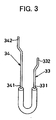
- the ceramic heater 3 is manufactured such that connection lead wires 33 and 34 and a U-shaped heat-generating resistor element 32 are embedded in a ceramic 31 made of mainly Si 3 N 4 .
- the resistance (design value) between the connection lead wires 33 and 34 is 750 m
- the heat-generating resistor element 32 is embedded in the ceramic 31 so as to be located at least 0.3 mm from the surface.
- the heat-generating resistor element 32 is designed to be heated to 800 - 1300C.
- connection lead wires 33 and 34 are formed of W (tungsten) wire having a diameter of 0.3 mm.
- the first ends 331 and 341 of the lead wires 33 and 34 are respectively connected to the end portions 321 and 322 of the heat-generating resistor element 32, whereas the second ends 332 and 342 of the lead wires 33 and 34 are respectively exposed from the surface of the ceramic at intermediate and rear positions.
- connection lead wire 33 is electrically connected to the body member 2 through a metallic tube 51 and the metallic outer sleeve 1 (see FIG. 2).
- connection lead wire 34 is electrically connected to the terminal electrode 4 through a metallic cap member 52.
- the terminal electrode 4 having a thread 41 is fixed to the body member 2 in an insulated manner through use of an insulator 61 and a nut 62 .
- Numeral 63 denotes a nut for fixing a power supply metal piece (not shown) to the terminal electrode 4.
- the glow plug A is produced through the following process.
- the metallic tube 51 and the metallic cap member 52 are inserted in the metallic outer sleeve 1, and the rear portion 11 of the metallic outer sleeve 1 is silver-alloy brazed to the inner wall 20 of the front end of the body member 2.
- terminal electrode 4 is fixed to the body member 2 via the insulator 61 and the nut 62.
- the heaters were allowed to stand in a furnace at 900°C and 1400°C for 100 hours each and the increased amount of oxidation (mg/cm 2 ) was measured.
- the ceramic heaters of the present invention were confirmed to be superior to the comparative ceramic heaters in terms of both mechanical strength (at ambient temperature and high temperature) and acid resistance.
- Glow plugs comprising the ceramic heaters ((1)-(7)) of the present invention and glow plugs comprising the comparative ceramic heaters ((8)-(13)) were disposed in an engine, and a cycle operation in the range of 400 to 900°C was conducted in order to evaluate mechanical strength and acid resistance.
- the test results demonstrate that the glow plugs comprising the ceramic heaters ((1)-(7)) of the present invention are superior to the glow plugs comprising the comparative ceramic heaters ((8)-(13)) in terms of both mechanical strength and acid resistance.
Landscapes
- Engineering & Computer Science (AREA)
- Chemical & Material Sciences (AREA)
- Ceramic Engineering (AREA)
- Combustion & Propulsion (AREA)
- Mechanical Engineering (AREA)
- General Engineering & Computer Science (AREA)
- Resistance Heating (AREA)
- Ceramic Products (AREA)
Claims (8)
- Keramikheizelement (3), das eine Keramik (31), die Siliziumnitrid als eine Hauptkomponente enthält, und ein Heizelement (32), das in der Keramik (31) eingebettet ist, umfasst, dadurch gekennzeichnet, dass
das Heizelement (32) vorwiegend aus einem Silizid, Carbid oder Nitrid mindestens eines Elements ausgebildet ist, das aus der Gruppe bestehend aus W, Ta, Nb, Ti, Mo, Zr, Hf, V und Cr ausgewählt ist, und
die Keramik (31) als Sinterhilfsmittel1 bis 20 Gew.-% mindestens eines Seltenerdelements, berechnet als dessen Oxid,0,5 bis 8 Gew.-% V (Vanadium), berechnet als V2O5, und0,5 bis 8 Gew.-% mindestens eines Elements der Gruppe Va/VIa, das aus der Gruppe bestehend aus Nb, Ta, Cr, Mo und W ausgewählt ist, berechnet als dessen Oxid, umfasst,wobei der Gesamtanteil von Vanadium und des Va/VIa-Elements 1 bis 10 Gew.-%, berechnet als Oxide, beträgt. - Verfahren zur Herstellung eines Keramikheizelements (3), das die Schritte umfasst:Herstellen von Körnern, die als Hauptkomponente ein Silizid, Carbid oder Nitrid mindestens eines Elements, das aus der Gruppe bestehend aus W, Ta, Nb, Ti, Mo, Zr, Hf, V und Cr ausgewählt ist, enthalten,Unterziehen der Körner zusammen mit Verbindungsanschlussdrähten (33, 34) einem Formverfahren, so dass ein ungebranntes Heizelement (32) erhalten wird,Herstellen eines Pulvergemischs, das Siliziumnitrid und als Sinterhilfsmittel 1 bis 20 Gew.-% mindestens eines Seltenerdelements, berechnet als dessen Oxid, 0,5 bis 8 Gew.-% V (Vanadium), berechnet als V2O5, und 0,5 bis 8 Gew.-% mindestens eines Elements der Gruppe Va/VIa, das aus der Gruppe bestehend aus Nb, Ta, Cr, Mo und W ausgewählt ist, berechnet als dessen Oxid, umfasst, wobei der Gesamtanteil von Vanadium und des Va/VIa-Elements 1 bis 10 Gew.-%, berechnet als Oxide, beträgt,Einbetten des ungebrannten Heizelements (32) in dem Pulvergemisch,Formen des Pulvergemischs, welches das Heizelement (32) enthält, zu einer gewünschten Form,Brennen des geformten Gemischs zum Erhalten eines Sinterkörpers, undSchleifen des Sinterkörpers derart, dass die Verbindungsdrahtanschlüsse (33, 34) partiell freigelegt werden.
- Keramikheizelement (3) nach Anspruch 1 oder Verfahren zur Herstellung eines Keramikheizelements nach Anspruch 2, bei dem die Menge des mindestens einen Seltenerdelements 1 bis 15 Gew.-%, berechnet als dessen Oxid, beträgt.
- Keramikheizelement (3) nach Anspruch 1 oder Anspruch 3 oder Verfahren zur Herstellung eines Keramikheizelements (3) nach Anspruch 2 oder Anspruch 3, bei dem die Menge von V (Vanadium) 1 bis 5 Gew.-%, berechnet als V2O5, beträgt.
- Keramikheizelement (3) nach einem der Ansprüche 1, 3 und 4 oder Verfahren zur Herstellung eines Keramikheizelements (3) nach einem der Ansprüche 2 bis 4, bei dem die Menge des mindestens einen Elements der Gruppe Va/VIa 1 bis 5 Gew.-%, berechnet als dessen Oxid, beträgt.
- Keramikheizelement (3) nach einem der Ansprüche 1, 3, 4 und 5 oder Verfahren zur Herstellung eines Keramikheizelements (3) nach einem der Ansprüche 2 bis 5, bei dem der Gesamtanteil von Vanadium und des Va/VIa-Elements 2 bis 6 Gew.-%, berechnet als Oxide, beträgt.
- Keramikglühkerze, die das Keramikheizelement (3) nach einem der Ansprüche 1 und 3 bis 6 umfasst.
- Keramikglühkerze (A), die ein Keramikheizelement (3) umfasst, das mit dem Verfahren nach einem der Ansprüche 2 bis 6 hergestellt worden ist.
Applications Claiming Priority (3)
| Application Number | Priority Date | Filing Date | Title |
|---|---|---|---|
| JP10439497 | 1997-04-22 | ||
| JP104394/97 | 1997-04-22 | ||
| JP9104394A JPH10300085A (ja) | 1997-04-22 | 1997-04-22 | セラミックヒータおよびセラミックグロープラグ |
Publications (3)
| Publication Number | Publication Date |
|---|---|
| EP0874197A2 EP0874197A2 (de) | 1998-10-28 |
| EP0874197A3 EP0874197A3 (de) | 2004-03-24 |
| EP0874197B1 true EP0874197B1 (de) | 2006-05-17 |
Family
ID=14379528
Family Applications (1)
| Application Number | Title | Priority Date | Filing Date |
|---|---|---|---|
| EP98303101A Expired - Lifetime EP0874197B1 (de) | 1997-04-22 | 1998-04-22 | Keramisches Heizelement, keramische Glühkerze und Herstellungsverfahren des Heizelements |
Country Status (5)
| Country | Link |
|---|---|
| US (1) | US5883360A (de) |
| EP (1) | EP0874197B1 (de) |
| JP (1) | JPH10300085A (de) |
| BR (1) | BR9801881A (de) |
| DE (1) | DE69834525T2 (de) |
Families Citing this family (23)
| Publication number | Priority date | Publication date | Assignee | Title |
|---|---|---|---|---|
| JPH10208853A (ja) * | 1996-11-19 | 1998-08-07 | Ngk Spark Plug Co Ltd | セラミックヒータ、およびその製造方法 |
| US6025579A (en) * | 1996-12-27 | 2000-02-15 | Jidosha Kiki Co., Ltd. | Ceramic heater and method of manufacturing the same |
| JP3691649B2 (ja) * | 1997-10-28 | 2005-09-07 | 日本特殊陶業株式会社 | セラミックヒータ |
| US6144015A (en) * | 1998-09-25 | 2000-11-07 | General Motors Corporation | Glow sensor--ceramic flat plate |
| US6274855B1 (en) * | 1998-11-17 | 2001-08-14 | Ngk Spark Plug Co., Ltd. | Heating resistor for ceramic heaters, ceramic heaters and method of manufacturing ceramic heaters |
| JP3933345B2 (ja) * | 1999-05-21 | 2007-06-20 | 日本特殊陶業株式会社 | 発熱抵抗体及びセラミックヒータ用発熱抵抗体並びにその製造方法、及びセラミックヒータ |
| JP2001132949A (ja) * | 1999-10-29 | 2001-05-18 | Ngk Spark Plug Co Ltd | セラミックヒータ及びグロープラグ |
| WO2001066488A1 (en) * | 2000-03-07 | 2001-09-13 | Ibiden Co., Ltd. | Ceramic substrate for manufacture/inspection of semiconductor |
| GB0006598D0 (en) * | 2000-03-17 | 2000-05-10 | Isis Innovation | Three-dimensional reconstructions from images |
| GB0028491D0 (en) * | 2000-11-22 | 2001-01-10 | Isis Innovation | Detection of features in images |
| JP4454191B2 (ja) * | 2001-07-30 | 2010-04-21 | 日本特殊陶業株式会社 | セラミックヒータの製造方法 |
| JP4553529B2 (ja) * | 2001-08-28 | 2010-09-29 | 日本特殊陶業株式会社 | セラミックヒータ及びそれを用いたグロープラグ |
| JP2003148731A (ja) * | 2001-08-28 | 2003-05-21 | Ngk Spark Plug Co Ltd | グロープラグ |
| US7223942B2 (en) * | 2004-06-29 | 2007-05-29 | Ngk Spark Plug Co., Ltd. | Ceramic heater, glow plug, and ceramic heater manufacturing method |
| JP4854459B2 (ja) * | 2006-10-06 | 2012-01-18 | 住友電気工業株式会社 | グロープラグ |
| KR101167557B1 (ko) * | 2007-10-29 | 2012-07-27 | 쿄세라 코포레이션 | 세라믹 히터 및 이것을 구비한 글로 플러그 |
| EP2257119B1 (de) * | 2008-02-20 | 2018-04-04 | Ngk Spark Plug Co., Ltd. | Keramik-heizelement und glühkerze |
| US20100078421A1 (en) * | 2008-10-01 | 2010-04-01 | Federal-Mogul Italy Sr1 | Glow plug adn heater assembly therefor with an improved connection between a central electrode and a heater probe of the heater assembly |
| JP5732798B2 (ja) * | 2010-09-29 | 2015-06-10 | 住友大阪セメント株式会社 | セラミック部材 |
| DE102010055630B4 (de) * | 2010-12-22 | 2014-05-22 | Webasto Ag | Integraler Sinterkörper für Hochtemperaturanwendungen |
| EP2753144B1 (de) * | 2011-08-29 | 2019-07-17 | Kyocera Corporation | Heizelement und damit versehene glühkerze |
| JP6140955B2 (ja) * | 2011-12-21 | 2017-06-07 | 日本特殊陶業株式会社 | セラミックヒータの製造方法 |
| EP2822356B1 (de) * | 2012-02-29 | 2018-05-30 | Kyocera Corporation | Heizelement und damit versehene glühkerze |
Family Cites Families (17)
| Publication number | Priority date | Publication date | Assignee | Title |
|---|---|---|---|---|
| US4486651A (en) * | 1982-01-27 | 1984-12-04 | Nippon Soken, Inc. | Ceramic heater |
| JPS5991685A (ja) * | 1982-11-17 | 1984-05-26 | 株式会社デンソー | セラミツクヒ−タ |
| US4556780A (en) * | 1983-10-17 | 1985-12-03 | Nippondenso Co., Ltd. | Ceramic heater |
| US4725711A (en) * | 1984-08-27 | 1988-02-16 | Jidosha Kiki Co., Ltd. | Self temperature control type glow plug |
| EP0286127B1 (de) * | 1987-04-10 | 1993-10-27 | Hitachi, Ltd. | Keramischer Verbundwerkstoff und Verfahren zu seiner Herstellung |
| JPH01313362A (ja) * | 1988-06-09 | 1989-12-18 | Ngk Spark Plug Co Ltd | セラミック発熱体およびその製造方法 |
| JP2948963B2 (ja) * | 1991-02-26 | 1999-09-13 | 京セラ株式会社 | セラミック発熱体 |
| CA2068979A1 (en) * | 1991-06-24 | 1992-12-25 | Allan B. Rosenthal | Silicon nitride ceramics containing a dispersed pentamolybdenum trisilicide base |
| JP2804393B2 (ja) * | 1991-07-31 | 1998-09-24 | 京セラ株式会社 | セラミックヒータ |
| JP2735721B2 (ja) * | 1991-12-26 | 1998-04-02 | 京セラ株式会社 | セラミック発熱体 |
| JP2735725B2 (ja) * | 1992-02-19 | 1998-04-02 | 京セラ株式会社 | セラミック発熱体 |
| US5304778A (en) * | 1992-11-23 | 1994-04-19 | Electrofuel Manufacturing Co. | Glow plug with improved composite sintered silicon nitride ceramic heater |
| JP3078418B2 (ja) * | 1993-02-26 | 2000-08-21 | 京セラ株式会社 | セラミック発熱体 |
| WO1995022512A1 (en) * | 1994-02-16 | 1995-08-24 | University Of Cincinnati | Method for joining ceramic and metal-ceramic heating elements to electrical terminals by micropyretic synthesis, compositions for electrical terminals and heaters comprising the same |
| JPH08227933A (ja) * | 1995-02-20 | 1996-09-03 | Shin Etsu Chem Co Ltd | 静電吸着機能を有するウエハ加熱装置 |
| JP4445595B2 (ja) * | 1995-09-12 | 2010-04-07 | 日本特殊陶業株式会社 | セラミックヒータ、セラミックグロープラグおよびその製造方法 |
| BR9700464A (pt) * | 1996-03-29 | 1998-11-03 | Ngk Spark Plug Co | Aquecedor cerâmico |
-
1997
- 1997-04-22 JP JP9104394A patent/JPH10300085A/ja active Pending
-
1998
- 1998-04-01 BR BR9801881-7A patent/BR9801881A/pt not_active IP Right Cessation
- 1998-04-15 US US09/060,474 patent/US5883360A/en not_active Expired - Lifetime
- 1998-04-22 DE DE69834525T patent/DE69834525T2/de not_active Expired - Lifetime
- 1998-04-22 EP EP98303101A patent/EP0874197B1/de not_active Expired - Lifetime
Also Published As
| Publication number | Publication date |
|---|---|
| JPH10300085A (ja) | 1998-11-13 |
| DE69834525T2 (de) | 2007-05-03 |
| US5883360A (en) | 1999-03-16 |
| EP0874197A3 (de) | 2004-03-24 |
| EP0874197A2 (de) | 1998-10-28 |
| BR9801881A (pt) | 1999-12-14 |
| DE69834525D1 (de) | 2006-06-22 |
Similar Documents
| Publication | Publication Date | Title |
|---|---|---|
| EP0874197A2 (de) | Keramisches Heizelement, keramische Glühkerze und Herstellungsverfahren des Heizelements | |
| JP3411498B2 (ja) | セラミックヒータ、その製造方法、及びセラミックグロープラグ | |
| EP2107854B1 (de) | Keramik-heizelement und glühkerze | |
| JP4445595B2 (ja) | セラミックヒータ、セラミックグロープラグおよびその製造方法 | |
| KR100399114B1 (ko) | 세라믹히터 | |
| EP1054577B1 (de) | Heizwiderstände, Heizwiderstände, die für keramischen Heizelementen bestimmt sind, und keramische Heizelemente, die diegleichen benützen | |
| CN100415061C (zh) | 陶瓷加热器以及具有该加热器的电热塞 | |
| JP4454191B2 (ja) | セラミックヒータの製造方法 | |
| US6599457B2 (en) | Process for producing silicon nitride sintered body for use in ceramic heater for use in glow plug | |
| JP3766786B2 (ja) | セラミックヒータ及びそれを備えるグロープラグ | |
| JPH08268760A (ja) | セラミックヒータ及びその製造方法 | |
| JP3664567B2 (ja) | セラミックヒータおよびセラミックグロープラグ | |
| EP1120998A1 (de) | Keramisches Heizelement und damit versehene Glühkerze | |
| EP2869666B1 (de) | Heizelement und damit versehene glühkerze | |
| JP3807813B2 (ja) | セラミックヒータ及びセラミックグロープラグ | |
| JP2002124365A (ja) | セラミックヒータ及びその製造方法 | |
| JP2948963B2 (ja) | セラミック発熱体 | |
| KR0148449B1 (ko) | 나선형 발열체 팁을 갖는 세라믹 글로우 플러그 | |
| JP3689526B2 (ja) | セラミックヒータ | |
| JP3903458B2 (ja) | セラミックヒータ及びそれを備えるグロープラグ | |
| JP3874581B2 (ja) | セラミックヒータ及びこれを用いたグロープラグ | |
| JP6392271B2 (ja) | セラミック焼結体、セラミックヒータおよびグロープラグ | |
| JP2001132948A (ja) | セラミックヒータ及びそれを備えるグロープラグ | |
| JP2000173749A (ja) | セラミックヒータ用発熱抵抗体及びセラミックヒータ並びにセラミックヒータの製造方法 | |
| JP2001153360A (ja) | セラミックヒータ及びそれを備えるグロープラグ |
Legal Events
| Date | Code | Title | Description |
|---|---|---|---|
| PUAI | Public reference made under article 153(3) epc to a published international application that has entered the european phase |
Free format text: ORIGINAL CODE: 0009012 |
|
| AK | Designated contracting states |
Kind code of ref document: A2 Designated state(s): AT BE CH CY DE DK ES FI FR GB GR IE IT LI LU MC NL PT SE |
|
| AX | Request for extension of the european patent |
Free format text: AL;LT;LV;MK;RO;SI |
|
| PUAL | Search report despatched |
Free format text: ORIGINAL CODE: 0009013 |
|
| AK | Designated contracting states |
Kind code of ref document: A3 Designated state(s): AT BE CH CY DE DK ES FI FR GB GR IE IT LI LU MC NL PT SE |
|
| AX | Request for extension of the european patent |
Extension state: AL LT LV MK RO SI |
|
| 17P | Request for examination filed |
Effective date: 20040329 |
|
| AKX | Designation fees paid |
Designated state(s): DE FR IT |
|
| GRAP | Despatch of communication of intention to grant a patent |
Free format text: ORIGINAL CODE: EPIDOSNIGR1 |
|
| GRAS | Grant fee paid |
Free format text: ORIGINAL CODE: EPIDOSNIGR3 |
|
| GRAA | (expected) grant |
Free format text: ORIGINAL CODE: 0009210 |
|
| AK | Designated contracting states |
Kind code of ref document: B1 Designated state(s): DE FR IT |
|
| PG25 | Lapsed in a contracting state [announced via postgrant information from national office to epo] |
Ref country code: IT Free format text: LAPSE BECAUSE OF FAILURE TO SUBMIT A TRANSLATION OF THE DESCRIPTION OR TO PAY THE FEE WITHIN THE PRE;WARNING: LAPSES OF ITALIAN PATENTS WITH EFFECTIVE DATE BEFORE 2007 MAY HAVE OCCURRED AT ANY TIME BEFORE 2007. THE CORRECT EFFECTIVE DATE MAY BE DIFFERENT FROM THE ONE RECORDED.SCRIBED TIME-LIMIT Effective date: 20060517 |
|
| REF | Corresponds to: |
Ref document number: 69834525 Country of ref document: DE Date of ref document: 20060622 Kind code of ref document: P |
|
| ET | Fr: translation filed | ||
| PLBE | No opposition filed within time limit |
Free format text: ORIGINAL CODE: 0009261 |
|
| STAA | Information on the status of an ep patent application or granted ep patent |
Free format text: STATUS: NO OPPOSITION FILED WITHIN TIME LIMIT |
|
| 26N | No opposition filed |
Effective date: 20070220 |
|
| PGFP | Annual fee paid to national office [announced via postgrant information from national office to epo] |
Ref country code: IT Payment date: 20090422 Year of fee payment: 12 |
|
| PG25 | Lapsed in a contracting state [announced via postgrant information from national office to epo] |
Ref country code: IT Free format text: LAPSE BECAUSE OF NON-PAYMENT OF DUE FEES Effective date: 20100422 |
|
| PGFP | Annual fee paid to national office [announced via postgrant information from national office to epo] |
Ref country code: DE Payment date: 20140430 Year of fee payment: 17 Ref country code: FR Payment date: 20140409 Year of fee payment: 17 |
|
| REG | Reference to a national code |
Ref country code: DE Ref legal event code: R119 Ref document number: 69834525 Country of ref document: DE |
|
| PG25 | Lapsed in a contracting state [announced via postgrant information from national office to epo] |
Ref country code: DE Free format text: LAPSE BECAUSE OF NON-PAYMENT OF DUE FEES Effective date: 20151103 |
|
| REG | Reference to a national code |
Ref country code: FR Ref legal event code: ST Effective date: 20151231 |
|
| PG25 | Lapsed in a contracting state [announced via postgrant information from national office to epo] |
Ref country code: FR Free format text: LAPSE BECAUSE OF NON-PAYMENT OF DUE FEES Effective date: 20150430 |