EP0874155A2 - Verdrängerverdichter - Google Patents
Verdrängerverdichter Download PDFInfo
- Publication number
- EP0874155A2 EP0874155A2 EP19980303092 EP98303092A EP0874155A2 EP 0874155 A2 EP0874155 A2 EP 0874155A2 EP 19980303092 EP19980303092 EP 19980303092 EP 98303092 A EP98303092 A EP 98303092A EP 0874155 A2 EP0874155 A2 EP 0874155A2
- Authority
- EP
- European Patent Office
- Prior art keywords
- valve
- pressure chamber
- plate
- refrigerant outlet
- refrigerant
- Prior art date
- Legal status (The legal status is an assumption and is not a legal conclusion. Google has not performed a legal analysis and makes no representation as to the accuracy of the status listed.)
- Withdrawn
Links
Images


Classifications
-
- F—MECHANICAL ENGINEERING; LIGHTING; HEATING; WEAPONS; BLASTING
- F04—POSITIVE - DISPLACEMENT MACHINES FOR LIQUIDS; PUMPS FOR LIQUIDS OR ELASTIC FLUIDS
- F04B—POSITIVE-DISPLACEMENT MACHINES FOR LIQUIDS; PUMPS
- F04B39/00—Component parts, details, or accessories, of pumps or pumping systems specially adapted for elastic fluids, not otherwise provided for in, or of interest apart from, groups F04B25/00 - F04B37/00
- F04B39/10—Adaptations or arrangements of distribution members
- F04B39/1066—Valve plates
-
- F—MECHANICAL ENGINEERING; LIGHTING; HEATING; WEAPONS; BLASTING
- F04—POSITIVE - DISPLACEMENT MACHINES FOR LIQUIDS; PUMPS FOR LIQUIDS OR ELASTIC FLUIDS
- F04B—POSITIVE-DISPLACEMENT MACHINES FOR LIQUIDS; PUMPS
- F04B39/00—Component parts, details, or accessories, of pumps or pumping systems specially adapted for elastic fluids, not otherwise provided for in, or of interest apart from, groups F04B25/00 - F04B37/00
- F04B39/10—Adaptations or arrangements of distribution members
- F04B39/1073—Adaptations or arrangements of distribution members the members being reed valves
- F04B39/1086—Adaptations or arrangements of distribution members the members being reed valves flat annular reed valves
-
- Y—GENERAL TAGGING OF NEW TECHNOLOGICAL DEVELOPMENTS; GENERAL TAGGING OF CROSS-SECTIONAL TECHNOLOGIES SPANNING OVER SEVERAL SECTIONS OF THE IPC; TECHNICAL SUBJECTS COVERED BY FORMER USPC CROSS-REFERENCE ART COLLECTIONS [XRACs] AND DIGESTS
- Y10—TECHNICAL SUBJECTS COVERED BY FORMER USPC
- Y10T—TECHNICAL SUBJECTS COVERED BY FORMER US CLASSIFICATION
- Y10T137/00—Fluid handling
- Y10T137/7722—Line condition change responsive valves
- Y10T137/7837—Direct response valves [i.e., check valve type]
- Y10T137/7838—Plural
- Y10T137/7843—Integral resilient member forms plural valves
Definitions
- This invention relates to a reciprocating compressor, such as a swash plate compressor, a wobble plate compressor, and an in-line compressor (crank compressor).
- a reciprocating compressor such as a swash plate compressor, a wobble plate compressor, and an in-line compressor (crank compressor).
- the present applicant proposed a reciprocating compressor (swash plate compressor) in Japanese Laid-Open Patent Publication (Kokai) No. 9-4563 (corresponding to US Patent No. 5,709,535).
- the proposed swash plate compressor includes a cylinder block having a plurality of compression chambers formed therein, a cylinder head which is secured to the cylinder block and has a discharge chamber and a suction chamber formed therein, a valve plate arranged between the cylinder block and the cylinder head for separating the compression chambers from the discharge chamber and the suction chamber, refrigerant outlet ports via which refrigerant gas is delivered from the compression chambers to the discharge chamber, refrigerant inlet ports via which refrigerant gas is drawn from the suction chamber into the compression chambers, discharge valves for opening and closing the refrigerant outlet ports, suction valves for opening and closing the refrigerant inlet ports, and stoppers for each setting a proper limit to an amount of opening or resilient deformation of a oorresponding one of the discharge valves.
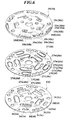
- FIG. 1 shows a valve plate, a valve sheet, and a stopper plate of another conventional reciprocating compressor (swash plate compressor) of this type, in an exploded state, which is proposed by the present applicant in Japanese Patent Application No. 9-14665, while FIG. 2 is a plan view of the stopper plate of the proposed compressor in a state in which the valve plate, the valve sheet, and the stopper plate are assembled.
- FIG. 3 is a partially sectional view taken on line III-III of FIG. 2.
- the discharge valves are formed by the valve sheet 327 and a plurality of discharge valve elements 327a integrally provided thereon, while the suction valves are formed by the same valve sheet 327 and a plurality of suction valve elements 327d integrally provided thereon.
- the discharge valve elements 327a and the suction valve elements 327d are each provided by cutting a portion of the valve sheet 327 into a tongue shape.
- the stoppers are formed by the stopper plate 329 arranged between the valve sheet 327 and the cylinder head 304, and a plurality of stopper portions 329a which are each formed by cutting a portion of the stopper plate 329 opposed to a corresponding one of the discharge valve elements 327a.
- the stopper plate 329 is also formed therethrough with the refrigerant inlet ports 329d as well as a plurality of slots 329b each open to the discharge chamber 324 for communicating between the discharge chamber 324 and a corresponding one of the refrigerant outlet ports 303a.
- the valve plate 303 is formed with the refrigerant outlet ports 303a as well as a plurality of relief holes 303b each open to a corresponding one of the compression chambers 321 for communicating between the compression chamber 321 and a corresponding one of the refrigerant inlet ports 329d.
- the proposed compressor employs the valve sheet 327 formed with the plurality of discharge valve elements 327a and suction valve elements 327d as well as the stopper plate 329 formed with the plurality of stopper portions 329a, component parts are reduced in number, and moreover, the valve plate 303, the valve sheet 327, and the stopper plate 329 can be simply placed on the cylinder block, one upon another, when they are assembled to the cylinder block, which markedly facilitates assembly of the compressor.
- valve plate 303 is deformed or distorted toward the compression chamber 321 during each suction stroke due to a difference in pressure between the discharge chamber 324 and the compression chamber 321, and if the amount of deformation of the valve plate 303 becomes large, high-pressure refrigerant gas delivered to the discharge chamber 324 flows back to the compression chamber 321, which results in degraded performance of the compressor.
- a solution to the problem of the back flow of refrigerant gas is to increase the thickness of the valve plate 303 so as to increase the rigidity of the valve plate 303.
- valve plate 303 if the thickness of the valve plate 303 is increased, volumes of the refrigerant outlet ports 303a and the relief holes 303b become larger to increase dead volume, causing degradation of volumetric efficiency of the compressor.
- a reciprocating compressor including a cylinder block having a plurality of compression chambers formed therein, the compression chambers being formed on at least one of opposite ends of respective pistons slidably received within respective cylinder bores, a cylinder head secured to the cylinder block and having a high-pressure chamber and a low-pressure chamber formed therein, and a separating member arranged between the cylinder block and the cylinder head, the separating member having a plurality of refrigerant inlet ports for suctioning a refrigerant gas from the low-pressure chamber into the compression chambers, a plurality of refrigerant outlet ports for discharging the refrigerant gas from the compression chambers into the high-pressure chamber, a plurality of suction valves for opening and closing the refrigerant inlet ports, respectively, and a plurality of discharge valves for opening and closing the refrigerant outlet ports, respectively.
- the reciprocating compressor according to the first aspect of the invention is characterized in that the separating member comprises:
- the relief holes each have a projecting portion formed integrally with a portion of the rim of the opening thereof in a manner bent in the direction of thickness of the valve plate. Therefore, it is possible to increase the rigidity of the valve plate without increasing thickness of the same, to thereby prevent deformation of the valve plate due to a difference in pressure between the high-pressure chamber and the compression chambers and a resultant back flow of high-pressure refrigerant gas from the high-pressure chamber into the compression chambers.
- the projecting portion is bent toward a partition wall of the cylinder head that separates the high-pressure chamber and the low-pressure chamber from each other, and received in a through hole formed through the valve sheet and a space formed in the stopper plate in a manner continuing from the through hole.
- the projecting portion is bent toward the partition wall of the cylinder head which separates the high-pressure chamber and the low-pressure chamber from each other, and received in the through hole formed through the valve sheet and the space formed in the stopper plate. Therefore, it is possible to increase the rigidity of the valve plate without increasing thickness of the same, to thereby prevent deformation of the valve plate due to a difference in pressure between the high-pressure chamber and the low-pressure chamber and a resultant back flow of high-pressure refrigerant gas from the high-pressure chamber to the compression chambers.
- the space comprises a through hole formed through the stopper plate
- the separating member further includes a gasket arranged between the stopper plate and the partition wall of the cylinder head for sealing the through hole of the stopper plate.
- the through hole of the stopper plate is defined by an inner peripheral wall formed with a recess, and the projecting portion has an end thereof bent at a right angle with respect to the direction of thickness of the valve plate and fitted in the recess.
- the end of the projecting portion is bent at a right angle with respect to the direction of thickness of the valve plate and fitted in the recess in the peripheral wall defining the through hole to thereby connect the valve plate and the stopper plate to each other, whereby the valve plate is inhibited from moving in the direction of thickness thereof, so that deformation or distortion of the plate can be prevented more reliably.
- the valve plate, the valve sheet, and the stopper plate are connected to each other to form a unit, which facilitates assembly of the compressor.
- the space comprises a recess formed in the stopper plate, and the projecting portion has an end thereof fitted in the recess.
- the valve plate since the end of the projecting portion is fitted in the recess, the valve plate is inhibited from moving in a radial direction, whereby deformation of the valve plate due to a difference in pressure between the high-pressure chamber and the low-pressure chamber is prevented. Further, the stopper plate has no holes formed therethrough for forming the spaces, so that the back flow of high-pressure refrigerant gas into the low-pressure chamber can be prevented.
- the valve plate further includes a projecting portion formed integrally with a portion of a rim of an opening of each of the refrigerant outlet ports in a manner bent in the direction of thickness of the valve plate.
- valve plate is formed with two kinds of projecting portions, the rigidity of the valve plate is further increased, which makes it possible to more reliably prevent the valve plate from being deformed or distorted due to a difference in pressure between the high-pressure chamber and the compression chamber.
- the discharge valves each comprise a tongue shaped portion cut from the valve sheet, the suction valves each comprising a tongue shaped portion cut from the valve sheet, the stoppers comprising a bottom of each of grooves formed in the stopper plate, the refrigerant outlet passages communicating with the grooves, respectively.
- a reciprocating compressor which is characterized in that the separating member comprises:
- the projecting portion is bent toward a partition wall of the cylinder head that separates the high-pressure chamber and the low-pressure chamber from each other, and received in a through hole formed through the valve sheet and a space formed in the stopper plate in a manner continuing from the through hole.
- FIG. 5 there is shown the whole arrangement of a swash plate compressor according to a first embodiment of the invention.
- the compressor has a cylinder block 1 on a front side, and a cylinder block 2 on a rear side, with respective opposed ends joined to each other via an O ring 38 to form an assembly of the cylinder blocks 1,2.
- the assembly of the cylinder blocks 1,2 has one end thereof secured to a front head (cylinder head) 4 via a valve plate 3, a valve sheet 27, and a stopper plate 29, and the other end thereof secured to a rear head (cylinder head) 6 via a valve plate 5, a valve sheet 28, and a stopper plate 30.
- a drive shaft 7 axially extends through the center of the assembly of the cylinder blocks 1, 2, and a swash plate 8 is rigidly fitted on the drive shaft 7.
- the drive shaft 7 and the swash plate 8 are rotatably supported in the assembly of the cylinder blocks 1, 2 via bearings 9, 10.
- the swash plate 8 is received within a swash plate chamber 37 defined within the assembly of the cylinder blocks 1, 2 at a joined portion thereof.
- the assembly of the cylinder blocks 1,2 has a plurality of cylinder bores 11 axially formed therethrough.
- the cylinder bores 11 are parallel to the axis of the drive shaft 7, and arranged at predetermined circumferential intervals about the drive shaft 7.
- Each cylinder bore 11 has a piston 12 slidably received therein.
- compression chambers 21, 22 are formed on opposite sides of the piston 12.
- the piston 12 is connected to the swash plate 8 via a pair of shoes 19, 20, each of which has a generally hemispherical shape, whereby the piston 12 reciprocates within the cylinder bore 11 as the swash plate 8 rotates.
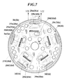
- FIG. 6 shows the valve plate, the valve sheet, and the stopper plate in an exploded state
- FIG. 7 is a plan view of the stopper plate in a state in which the valve plate, the valve sheet, and the stopper plate are assembled.
- FIG. 8 is a view taken on line VIII-VIII of FIG. 7.
- FIG. 4 is a view taken on line IV-IV of FIG. 7.
- the valve plate 3(5) which is generally disk-shaped, is formed therethrough with refrigerant outlet ports 3a(5a) via which refrigerant gas is delivered from the compression chambers 21(22) to a discharge chamber (high-pressure chamber) 24, relief holes 3b(5b) via each of which a suction valve element 27d(28d), referred to hereinbelow, opens toward a corresponding one of the compression chambers 21(22) during each suction stroke, and through holes 3c(5c) through which bolts, not shown, extend, respectively.
- the valve plate 3(5) is formed of a hot rolled steel (SPHC) or the like.
- Each of the relief holes 3b(5b) opens toward a corresponding one of the compression chambers 21(22), for communicating between the compression chamber 21(22) and a corresponding refrigerant inlet port 29d(30d), referred to hereinafter, when a corresponding suction valve element 27d(28d) opens.
- Each of the relief holes 3b(5b) has a projecting portion 3d(5d) formed integrally with a portion of a rim of an opening thereof. As shown in FIG. 4, the projecting portion 3d(5d) is formed in a manner bent toward a partition wall 4a(6a) separating the discharge chamber 24 and a suction chamber (low-pressure chamber) 23 from each other. The bent or protruded projecting portion 3d(5d) is received within a space 40 (see FIG. 4) formed through the valve sheet 27(28) and the stopper plate 29(30).
- the space 40 is formed by a slot 27f(28f), referred to hereinbelow, formed through the valve sheet 27(28) and a slot 29e(30e), also referred to hereinafter, formed through the stopper plate 29(30).
- the slots 27f(28f) and 29e(30e) are formed through the valve sheet 27(28) and the stopper plate 29(30), respectively, in a manner opposed to each other in a direction of thickness of the valve plate 3(5) (i.e. in a horizontal direction as viewed in FIG. 4).
- the valve sheet 27(28) which is generally disk-shaped, has a plurality of discharge valve elements 27a(28a) each cut into a tongue shape, i.e. defined by a slot 27g(28g), and the suction valve elements 27d(28d) each cut into a tongue shape, i.e. defined by the slot 27f(28f) and through holes 27c(28c) through which the bolts extend, respectively.
- the valve sheet 27(28) is formed e.g. of a leaf spring material. As shown in FIGS. 6 and 7, each of the discharge valve elements 27a(28a) and a corresponding one of the suction valve elements 27d(28d) are formed in a manner parallel to each other along length thereof with separating portion 27e(28e) formed therebetween.
- the tongue-shaped suction valve members 27d(28d) and discharge valve elements 27a(28a) as well as the U-shaped slots 27f(28f) defining the suction valve elements 27d(28d) and the U-shaped slots 27g(28g) defining the discharge valve elements 27a(28a) are formed in one operation by punching the valve sheet 27(28). As shown in FIG. 6, a separating portion-side half of the U-shaped slot 27f(28f) has a larger width than a central valve sheet-side half of the same.
- the stopper plate 29(30) which is generally disk-shaped, is formed with stopper portions 29a(30a). Each of the stopper portions 29a(30a) is formed by a recess opposed to a corresponding one of the tongue-shaped discharge valve elements 27a(28a). The stopper plate 29(30) is also formed with the refrigerant inlet ports 29d(30d) via which refrigerant gas is drawn from the suction chamber 23 into the compression chambers 21(22).
- the stopper plate 29(30) is formed of aluminum alloy, a hot rolled steel (SPHC) or the like. As shown in FIG.
- each stopper portion 29a(30a) has a bottom surface which is inclined at a predetermined angle with respect to a corresponding one of the discharge valve elements 27a(28a) in a valve-closing position or sloped at a predetermined curvature, thereby setting a proper limit to an amount of opening or resilient deformation of the discharge valve element 27a(28a).
- FIG. 8 shows the discharge valve element 27a(28a) in a valve-opening position.
- the stopper plate 29(30) also has slots (refrigerant outlet passage) 29b(30b) formed therethrough along length of the stopper portions 29a(30a) in a manner continuous with the recesses defining the stopper portions 29a(30a), respectively.
- Each of the slots 29b(30b) is open to the discharge chamber 24 for communicating between a corresponding one of the refrigerant outlet ports 3a(5a) when a corresponding discharge valve element 27a(28a) opens. Further, the stopper plate 29(30) is formed therethrough with the slots 29e(30e) in each of which is received the projecting portions 3d(5d) formed on the valve plate 3(5). A gasket 90(91) is interposed between the stopper plate 29(30) and the head 4(6).
- Each discharge valve element 27a(28a) is opposed to a corresponding one of the refrigerant outlet ports 3a(5a) formed through the valve plate 3(5) (see FIG. 8), and when the discharge valve element 27a(28a) opens, a corresponding one of the compression chambers 21(22) communicates with the discharge chamber 24 via the corresponding one of the refrigerant outlet ports 3a(5a) and a corresponding one of the slots 29b(30b) formed through the stopper plate 29(30).
- each of the suction valve elements 27d(28d) is opposed to a corresponding one of the refrigerant inlet ports 29d(30d) formed through the stopper plate 29(30), and when the suction valve element 27d(28d) opens, one of the compression chambers 21(22) communicates with the suction chamber 23 via the corresponding one of the refrigerant inlet ports 29d(30d) and a corresponding one of the relief holes 3b(5b).
- the swash plate 8 As the drive shaft 7 rotates, the swash plate 8 is rotated in unison therewith. According to the rotation of the swash plate 8, the piston 12 reciprocates within the cylinder bore 11.
- the piston 12 slides to a position shown in FIG. 5 (right-side extremity position in FIG. 5), whereby the suction stroke is completed in the compression chamber 21, while the compression stroke is completed in the compression chamber 22.
- the suction stroke is completed in the compression chamber 22, while the compression stroke is completed in the compression chamber 21.
- the suction valve element 27d(28d) is resiliently deformed or bent toward a corresponding one of the relief holes 3b(5b), whereby a corresponding one of the refrigerant inlet ports 29d(30d) opens, and low-pressure refrigerant gas flows from the suction chamber 23 into the compression chamber 21(22) via the refrigerant inlet port 29d(30d) and the relief hole 3b(5b).
- the discharge valve element 27a(28a) is resiliently deformed or bent toward the discharge chamber 24, whereby high-pressure refrigerant gas is delivered from the compression chamber 21(22) to the discharge chamber 24.
- the whole discharge valve element 27a(28a) abuts a bottom surface 42(43) of a corresponding one of the stopper portions 29a(30a), whereby the amount of opening or resilient deformation of the discharge valve element 27a(28a) is controlled.
- the swash plate compressor of the first embodiment it is possible to prevent a back flow of refrigerant gas from the discharge chamber 24 into the compression chamber 21(22) without increasing the thickness of the valve plate 3(5), so that an increase in dead volume within the compressor, which causes degradation of volumetric efficiency, can also be prevented.
- valve plate 3(5) has a simple construction for enhancing rigidity thereof, which facilitates manufacturing of the plate 3(5).
- the projecting portions 3d(5d) of the valve plate 3(5) can be formed by simply punching and pressing the valve plate 3(5).
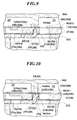
- FIG. 9 shows essential parts of a swash plate compressor according to a second embodiment, on an enlarged scale. Component parts and elements corresponding to those of the first embodiment are indicated by identical reference numerals, and description thereof is omitted.
- the space 40 is formed by the slots 27f(28f) formed through the valve sheet 27(28) and the slots 29e(30e) formed through the stopper plate 29(30), and the projecting portion 3d(5d) is received in the slots 27f(28f), 29e(30e) (i.e. in the space 40), while in the second embodiment, as shown in FIG.
- a space 140 is formed by the slots 27f(28f) formed through the valve sheet 27(28) and a recess 129e(130e) each formed in a stopper plate 129(130) in a manner opposed to a corresponding one of the slots 27f(28f) in the direction of thickness of the valve plate 3(5), and the projecting portion 3d(5d) is fitted in the recess 129e(130e).
- the second embodiment can provide the same effects as obtained by the first embodiment. Further, since the projecting portion 3d(5d) is fitted in the recess 129e(130e), the valve plate 3(5) is inhibited from moving in a radial direction (rightward and leftward as viewed in FIG. 9), whereby deformation of the valve plate 3(5) is further reliably prevented.
- the second embodiment is distinguished from the first embodiment in that the stopper plate 129(130) has no through hole or slot formed therethrough for forming the space 140. Therefore, it is possible to prevent high-pressure refrigerant gas from flowing into the suction chamber 23 from the compression chambers 21(22).
- FIG. 10 shows essential parts of a swash plate compressor according to a third embodiment, on an enlarged scale. Component parts and elements corresponding to those of the first embodiment are indicated by identical reference numerals, and description thereof is omitted.
- a space 240 is formed by the slot 27f(28f) formed through the valve sheet 27(28), a slot 229e(230e) formed through a stopper plate 229(230) in a manner opposed to a corresponding one of the slots 27f(28f) in the direction of thickness of the valve plate 3(5), and a recess 229f(230f) formed within the slot 229e(230e) by cutting away a portion of an inner peripheral wall of the slot 229e(230e).
- the projecting portion of the valve plate 3(5) has an end 3e(5e) bent at a substantially right angle with respect to the direction of thickness of the valve plate 3(5) and fitted in the recess 229f(230f).
- the third embodiment can provide the same effects as obtained by the first embodiment. Further, since the end 3e(5e) of the projecting portion 3d(5d) is fitted in the recess 229e(230e), the valve plate 3(5) is inhibited from moving in the direction of thickness of the valve plate 3(5) (i.e. upward and downward as viewed in FIG. 10), whereby deformation of the valve plate 3(5) is further reliably prevented.
- valve plate 3(5), the valve sheet 27(28), and the stopper plate 229(230) are joined to each other to form a unit, the components of the compressor including the valve plate 3(5) can be mounted in the compressor as the unit, which further facilitates assembly of the compressor in comparison with a conventional method in which the three components 3(5), 27(28), and 29(30) are mounted separately.
- the projecting portion 3d(5d) is formed integrally with the portion of the rim of the opening of the relief hole 3b(5b), this is not limitative, but the projecting portion 3d'(5d') may be formed integrally with a portion of a rim of an opening of the refrigerant outlet port 3a(5a) according to a fourth embodiment of the invention, as shown in FIG. 11. Further, alternatively, the relief hole 3b(5b) and the refrigerant outlet port 3a(5a) may both have the projecting portions 3d(5d) and 3'(5d') formed integrally with the rims of openings thereof, respectively.
Landscapes
- Engineering & Computer Science (AREA)
- Mechanical Engineering (AREA)
- General Engineering & Computer Science (AREA)
- Compressor (AREA)
- Compressors, Vaccum Pumps And Other Relevant Systems (AREA)
Applications Claiming Priority (3)
| Application Number | Priority Date | Filing Date | Title |
|---|---|---|---|
| JP11885497 | 1997-04-22 | ||
| JP118854/97 | 1997-04-22 | ||
| JP11885497A JPH10299656A (ja) | 1997-04-22 | 1997-04-22 | 往復式圧縮機 |
Publications (2)
| Publication Number | Publication Date |
|---|---|
| EP0874155A2 true EP0874155A2 (de) | 1998-10-28 |
| EP0874155A3 EP0874155A3 (de) | 2000-05-10 |
Family
ID=14746792
Family Applications (1)
| Application Number | Title | Priority Date | Filing Date |
|---|---|---|---|
| EP19980303092 Withdrawn EP0874155A3 (de) | 1997-04-22 | 1998-04-22 | Verdrängerverdichter |
Country Status (4)
| Country | Link |
|---|---|
| US (1) | US6022199A (de) |
| EP (1) | EP0874155A3 (de) |
| JP (1) | JPH10299656A (de) |
| CN (1) | CN1197162A (de) |
Cited By (2)
| Publication number | Priority date | Publication date | Assignee | Title |
|---|---|---|---|---|
| EP1116884A1 (de) * | 2000-01-17 | 2001-07-18 | Sanden Corporation | Verdichtereinlassventil |
| WO2001063126A1 (en) * | 2000-02-22 | 2001-08-30 | Embraco Europe S.R.L. | Compressor valve plate |
Families Citing this family (16)
| Publication number | Priority date | Publication date | Assignee | Title |
|---|---|---|---|---|
| US7004734B2 (en) * | 1999-12-28 | 2006-02-28 | Zexel Valco Climate Control Corporation | Reciprocating refrigerant compressor |
| US20040052665A1 (en) * | 2001-01-15 | 2004-03-18 | Ryosuke Izawa | Double-acting refrigerant compressor |
| US20050089412A1 (en) * | 2003-10-24 | 2005-04-28 | Chen Kwang-Tsan | Miniature air compressor |
| DE102004003137A1 (de) * | 2004-01-21 | 2005-08-11 | Behr Gmbh & Co. Kg | Kompressionsvorrichtung für gasförmige Medien |
| JP4408389B2 (ja) * | 2004-05-10 | 2010-02-03 | サンデン株式会社 | 斜板式圧縮機 |
| DE102004047159B4 (de) * | 2004-09-29 | 2006-09-07 | Danfoss Compressors Gmbh | Kolbenverdichter, insbesondere hermetischer Kältemittelverdichter |
| DE102005038783A1 (de) * | 2005-08-17 | 2007-02-22 | Danfoss Compressors Gmbh | Linearverdichter |
| JP5407333B2 (ja) * | 2007-01-23 | 2014-02-05 | 日本電気株式会社 | ダイヤフラムポンプ |
| JP5065120B2 (ja) * | 2008-03-28 | 2012-10-31 | サンデン株式会社 | 往復動圧縮機 |
| JP2011231733A (ja) * | 2010-04-30 | 2011-11-17 | Hitachi Appliances Inc | 密閉型圧縮機 |
| JP2012021400A (ja) * | 2010-07-12 | 2012-02-02 | Hitachi Appliances Inc | 密閉型圧縮機及びこれを備えた冷蔵庫 |
| NL1038701C2 (en) * | 2011-03-23 | 2012-09-25 | Aqua Gutta B V | Device for extracting humid from air by using a wind-turbine in combination with a mechanically driven heat-pump system, as well as heat-pump system applicable with such a device. |
| FR2993032B1 (fr) * | 2012-07-04 | 2014-07-11 | Valeo Sys Controle Moteur Sas | Vanne de controle moteur a etancheite amelioree |
| CN112682122B (zh) | 2016-10-06 | 2022-09-09 | 博格华纳公司 | 用于可变凸轮正时系统的双瓣阀 |
| US11111827B2 (en) | 2016-10-06 | 2021-09-07 | Borgwarner, Inc. | Double flapper valve for a variable cam timing system |
| GB2591468A (en) * | 2020-01-28 | 2021-08-04 | Ttp Ventus Ltd | Valve for controlling a flow of a fluid |
Citations (2)
| Publication number | Priority date | Publication date | Assignee | Title |
|---|---|---|---|---|
| JPH094563A (ja) | 1995-04-18 | 1997-01-07 | Zexel Corp | 往復式圧縮機 |
| JPH0914665A (ja) | 1995-06-29 | 1997-01-17 | Mitsubishi Electric Corp | 加熱調理器 |
Family Cites Families (6)
| Publication number | Priority date | Publication date | Assignee | Title |
|---|---|---|---|---|
| US4752190A (en) * | 1986-06-18 | 1988-06-21 | Tecumseh Products Company | Compressor cylinder head |
| US5213487A (en) * | 1991-06-26 | 1993-05-25 | Holset Engineering Company, Inc. | Ring valve type air compressor with deformable ring valves |
| WO1993018304A1 (fr) * | 1992-03-03 | 1993-09-16 | Matsushita Refrigeration Company | Compresseur hermetique |
| JPH06346840A (ja) * | 1993-06-08 | 1994-12-20 | Toyota Autom Loom Works Ltd | ウェーブカム式圧縮機 |
| JP3503154B2 (ja) * | 1993-10-01 | 2004-03-02 | 株式会社豊田自動織機 | 斜板式圧縮機 |
| US5878649A (en) * | 1998-04-07 | 1999-03-09 | Caterpillar Inc. | Controlled porting for a pressure transformer |
-
1997
- 1997-04-22 JP JP11885497A patent/JPH10299656A/ja not_active Withdrawn
-
1998
- 1998-04-20 US US09/063,250 patent/US6022199A/en not_active Expired - Fee Related
- 1998-04-22 CN CN98107318A patent/CN1197162A/zh active Pending
- 1998-04-22 EP EP19980303092 patent/EP0874155A3/de not_active Withdrawn
Patent Citations (3)
| Publication number | Priority date | Publication date | Assignee | Title |
|---|---|---|---|---|
| JPH094563A (ja) | 1995-04-18 | 1997-01-07 | Zexel Corp | 往復式圧縮機 |
| US5709535A (en) | 1995-04-18 | 1998-01-20 | Zexel Corporation | Multi-cylinder reciprocating compressor having improved discharge valve stopper assembly |
| JPH0914665A (ja) | 1995-06-29 | 1997-01-17 | Mitsubishi Electric Corp | 加熱調理器 |
Cited By (4)
| Publication number | Priority date | Publication date | Assignee | Title |
|---|---|---|---|---|
| EP1116884A1 (de) * | 2000-01-17 | 2001-07-18 | Sanden Corporation | Verdichtereinlassventil |
| US6382939B2 (en) | 2000-01-17 | 2002-05-07 | Sanden Corporation | Reciprocating compressor in which a suction valve is previously bent to open a suction port when the compressor is stopped |
| WO2001063126A1 (en) * | 2000-02-22 | 2001-08-30 | Embraco Europe S.R.L. | Compressor valve plate |
| US6971168B2 (en) | 2000-02-22 | 2005-12-06 | Embraco Europe S.R.L. | Compressor valve plate |
Also Published As
| Publication number | Publication date |
|---|---|
| CN1197162A (zh) | 1998-10-28 |
| EP0874155A3 (de) | 2000-05-10 |
| JPH10299656A (ja) | 1998-11-10 |
| US6022199A (en) | 2000-02-08 |
Similar Documents
| Publication | Publication Date | Title |
|---|---|---|
| US6022199A (en) | Reciprocating compressor | |
| US4778360A (en) | Suction and/or discharge valve port configuration for refrigerant compressor | |
| CA2019378A1 (en) | Positive stop for a suction leaf valve of a compressor | |
| US5709535A (en) | Multi-cylinder reciprocating compressor having improved discharge valve stopper assembly | |
| US7004734B2 (en) | Reciprocating refrigerant compressor | |
| US6174147B1 (en) | Refrigerant compressor with an improved discharge valve assembly | |
| EP0874156A2 (de) | Verdrängerverdichter | |
| JPH10266965A (ja) | 往復動型圧縮機 | |
| JP5273504B2 (ja) | 圧縮機 | |
| JPH10196542A (ja) | 往復式圧縮機 | |
| EP1571336A2 (de) | Kolbenverdichter | |
| JP4304544B2 (ja) | ピストン式圧縮機における冷媒吸入構造 | |
| JP2005105975A (ja) | 圧縮機の弁構造 | |
| JP3855952B2 (ja) | ピストン式圧縮機 | |
| JPH10196541A (ja) | 往復式圧縮機 | |
| JPH1193840A (ja) | 流体通路構造及び圧縮機 | |
| KR100859734B1 (ko) | 압축기 | |
| JP2000018160A (ja) | 往復式圧縮機 | |
| JP2002349440A (ja) | 往復式冷媒圧縮機 | |
| EP3896284B1 (de) | Taumelscheibenverdichter | |
| JPH1193834A (ja) | 往復式圧縮機 | |
| US20040052665A1 (en) | Double-acting refrigerant compressor | |
| JP2005083348A (ja) | 圧縮機 | |
| US20080193304A1 (en) | Piston Type Compressor | |
| KR100596159B1 (ko) | 용량가변형 사판식 압축기용 피스톤 및 그 제조방법 |
Legal Events
| Date | Code | Title | Description |
|---|---|---|---|
| PUAI | Public reference made under article 153(3) epc to a published international application that has entered the european phase |
Free format text: ORIGINAL CODE: 0009012 |
|
| AK | Designated contracting states |
Kind code of ref document: A2 Designated state(s): DE FR GB SE |
|
| AX | Request for extension of the european patent |
Free format text: AL;LT;LV;MK;RO;SI |
|
| PUAL | Search report despatched |
Free format text: ORIGINAL CODE: 0009013 |
|
| AK | Designated contracting states |
Kind code of ref document: A3 Designated state(s): AT BE CH CY DE DK ES FI FR GB GR IE IT LI LU MC NL PT SE |
|
| AX | Request for extension of the european patent |
Free format text: AL;LT;LV;MK;RO;SI |
|
| 17P | Request for examination filed |
Effective date: 20000718 |
|
| AKX | Designation fees paid |
Free format text: DE FR GB SE |
|
| RAP1 | Party data changed (applicant data changed or rights of an application transferred) |
Owner name: BOSCH AUTOMOTIVE SYSTEMS CORPORATION |
|
| RAP1 | Party data changed (applicant data changed or rights of an application transferred) |
Owner name: ZEXEL VALEO CLIMATE CONTROL CORPORATION |
|
| 17Q | First examination report despatched |
Effective date: 20021014 |
|
| STAA | Information on the status of an ep patent application or granted ep patent |
Free format text: STATUS: THE APPLICATION IS DEEMED TO BE WITHDRAWN |
|
| 18D | Application deemed to be withdrawn |
Effective date: 20030225 |