EP0874156A2 - Verdrängerverdichter - Google Patents
Verdrängerverdichter Download PDFInfo
- Publication number
- EP0874156A2 EP0874156A2 EP98303118A EP98303118A EP0874156A2 EP 0874156 A2 EP0874156 A2 EP 0874156A2 EP 98303118 A EP98303118 A EP 98303118A EP 98303118 A EP98303118 A EP 98303118A EP 0874156 A2 EP0874156 A2 EP 0874156A2
- Authority
- EP
- European Patent Office
- Prior art keywords
- valve
- plate
- valve sheet
- sheet
- reciprocating compressor
- Prior art date
- Legal status (The legal status is an assumption and is not a legal conclusion. Google has not performed a legal analysis and makes no representation as to the accuracy of the status listed.)
- Withdrawn
Links
- 239000003507 refrigerant Substances 0.000 claims abstract description 59
- 230000006835 compression Effects 0.000 claims abstract description 45
- 238000007906 compression Methods 0.000 claims abstract description 45
- 239000000853 adhesive Substances 0.000 claims description 20
- 230000001070 adhesive effect Effects 0.000 claims description 20
- 229910000831 Steel Inorganic materials 0.000 description 2
- 230000015556 catabolic process Effects 0.000 description 2
- 238000006731 degradation reaction Methods 0.000 description 2
- 230000000694 effects Effects 0.000 description 2
- 238000003754 machining Methods 0.000 description 2
- 239000010959 steel Substances 0.000 description 2
- 229910000838 Al alloy Inorganic materials 0.000 description 1
- 238000007796 conventional method Methods 0.000 description 1
- 230000003247 decreasing effect Effects 0.000 description 1
- 238000007599 discharging Methods 0.000 description 1
- 230000033001 locomotion Effects 0.000 description 1
- 239000000463 material Substances 0.000 description 1
- 230000004048 modification Effects 0.000 description 1
- 238000012986 modification Methods 0.000 description 1
Images


Classifications
-
- F—MECHANICAL ENGINEERING; LIGHTING; HEATING; WEAPONS; BLASTING
- F04—POSITIVE - DISPLACEMENT MACHINES FOR LIQUIDS; PUMPS FOR LIQUIDS OR ELASTIC FLUIDS
- F04B—POSITIVE-DISPLACEMENT MACHINES FOR LIQUIDS; PUMPS
- F04B27/00—Multi-cylinder pumps specially adapted for elastic fluids and characterised by number or arrangement of cylinders
- F04B27/08—Multi-cylinder pumps specially adapted for elastic fluids and characterised by number or arrangement of cylinders having cylinders coaxial with, or parallel or inclined to, main shaft axis
- F04B27/10—Multi-cylinder pumps specially adapted for elastic fluids and characterised by number or arrangement of cylinders having cylinders coaxial with, or parallel or inclined to, main shaft axis having stationary cylinders
- F04B27/1009—Distribution members
-
- F—MECHANICAL ENGINEERING; LIGHTING; HEATING; WEAPONS; BLASTING
- F04—POSITIVE - DISPLACEMENT MACHINES FOR LIQUIDS; PUMPS FOR LIQUIDS OR ELASTIC FLUIDS
- F04B—POSITIVE-DISPLACEMENT MACHINES FOR LIQUIDS; PUMPS
- F04B39/00—Component parts, details, or accessories, of pumps or pumping systems specially adapted for elastic fluids, not otherwise provided for in, or of interest apart from, groups F04B25/00 - F04B37/00
- F04B39/10—Adaptations or arrangements of distribution members
- F04B39/1073—Adaptations or arrangements of distribution members the members being reed valves
- F04B39/1086—Adaptations or arrangements of distribution members the members being reed valves flat annular reed valves
Definitions
- This invention relates to a reciprocating compressor, such as a swash plate compressor, a wobble plate compressor, and an in-line compressor (crank compressor).
- a reciprocating compressor such as a swash plate compressor, a wobble plate compressor, and an in-line compressor (crank compressor).
- the present applicant proposed a reciprocating compressor (swash plate compressor) in Japanese Laid-Open Patent Publication (Kokai) No. 9-4563 (corresponding to US Patent No. 5,709,535).
- the proposed swash plate compressor includes a cylinder block having a plurality of compression chambers formed therein, a cylinder head which is secured to the cylinder block and has a discharge chamber and a suction chamber formed therein, a valve plate arranged between the cylinder block and the cylinder head for separating the compression chambers from the discharge chamber and the suction chamber, refrigerant outlet ports via which refrigerant gas is delivered from the compression chambers to the discharge chamber, refrigerant inlet ports via which refrigerant gas is drawn from the suction chamber into the compression chambers, discharge valves for opening and closing the refrigerant outlet ports, suction valves for opening and closing the refrigerant inlet ports, and stoppers for each setting a proper limit to an amount of opening or resilient deformation of a corresponding one of the discharge valves.
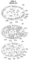
- FIG. 1 shows a valve plate, a valve sheet, and a stopper plate of another conventional reciprocating compressor (swash plate compressor) of this type, in an exploded state, which is proposed by the present applicant in Japanese Patent Application No. 9-14665, while FIG. 2 is a plan view of the stopper plate of the proposed compressor in a state in which the valve plate, the valve sheet, and the stopper plate are assembled.
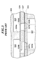
- FIG. 3 is a partially sectional view taken on line III-III of FIG. 2.
- the discharge valves are formed by the valve sheet 327 and a plurality of discharge valve elements 327a integrally provided thereon, while the suction valves are formed by the same valve sheet 327 and a plurality of suction valve elements 327d integrally provided thereon.
- the discharge valve elements 327a and the suction valve elements 327d are each provided by cutting a portion of the valve sheet 327 into a tongue shape.
- the stoppers are formed by the stopper plate 329 arranged between the valve sheet 327 and the cylinder head 304, and a plurality of stopper portions 329a which are each formed by cutting a portion of the stopper plate 329 opposed to a corresponding one of the discharge valve elements 327a.
- the stopper plate 329 is also formed therethrough with the refrigerant inlet ports 329d as well as a plurality of slots 329b each open to the discharge chamber 324 for communicating between the discharge chamber 324 and a corresponding one of the refrigerant outlet ports 303a.
- the valve plate 303 is formed with the refrigerant outlet ports 303a as well as a plurality of relief holes 303b each open to a corresponding one of the compression chambers 321 for communicating between the compression chamber 321 and a corresponding one of the refrigerant inlet ports 329d.
- the proposed compressor employs the valve sheet 327 formed with the plurality of discharge valve elements 327a and suction valve elements 327d as well as the stopper plate 329 formed with the plurality of stopper portions 329a, component parts are reduced in number, and moreover, the valve plate 303, the valve sheet 327, and the stopper plate 329 can be simply placed on the cylinder block, one upon another, when they are assembled to the cylinder block, which markedly facilitates assembly of the compressor.
- valve plate 303 is deformed or distorted toward the compression chamber 321 during each suction stroke due to a difference in pressure between the discharge chamber 324 and the compression chamber 321, and if the amount of deformation of the valve plate 303 becomes large, high-pressure refrigerant gas delivered to the discharge chamber 324 flows back to the compression chamber 321, which results in degraded performance of the compressor.
- a solution to the problem of the back flow of refrigerant gas is to increase the thickness of the valve plate 303 so as to increase the rigidity of the valve plate 303.
- valve plate 303 if the thickness of the valve plate 303 is increased, volumes of the refrigerant outlet ports 303a and the relief holes 303b become larger to increase dead volume, causing degradation of volumetric efficiency of the compressor.
- valve plate 303, the valve sheet 327, and the stopper plate 329 are simply placed on the cylinder block, one upon another, to markedly facilitate the assembly of them to the cylinder block, it is still required to further facilitate assembly of the compressor.
- the present invention provides a reciprocating compressor including a cylinder block having a plurality of compression chambers formed therein, the compression chambers being formed on at least one of opposite ends of respective pistons slidably received within respective cylinder bores, a cylinder head secured to the cylinder block and having a high-pressure chamber and a low-pressure chamber formed therein, and a separating member arranged between the cylinder block and the cylinder head, the separating member having a plurality of refrigerant inlet ports for suctioning a refrigerant gas from the low-pressure chamber into the compression chambers, a plurality of refrigerant outlet ports for discharging the refrigerant gas from the compression chambers into the high-pressure chamber, a plurality of suction valves for opening and closing the refrigerant inlet ports, respectively, and a plurality of discharge valves for opening and closing the refrigerant outlet ports, respectively.
- the reciprocating compressor according to the invention is characterized in that the separating member comprises:
- valve plate and the stopper plate are joined to the valve sheet, it is possible to prevent deformation or distortion of the valve plate due to a difference in pressure between the high-pressure chamber and the compression chamber without increasing thickness of the valve plate, to thereby prevent high-pressure refrigerant gas from flowing back from the high-pressure chamber to the compression chamber. Further, since the valve plate, the valve sheet, and the stopper plate are fastened or joined to form a unit, these components including the valve plate can be easily assembled into the reciprocating compressor as the unit.
- the fastening means comprises at least one rivet.
- the assembled state can be maintained over a long time period.
- the valve sheet has a plurality of fastening portions located between the discharge valves and corresponding ones of the suction valves, respectively, the at least one rivet extending respectively through the fastening portions.
- the fastening means comprises an adhesive.
- valve plate is not required to be formed with any through holes or slots through which fastening members, such as the rivets, it is possible to maintain required rigidity of the valve plate. Further, since it is not required, either, to carry out machining on a piston within each cylinder bore, the compressor can be manufactured with ease.
- the valve sheet has a plurality of fastening portions located between the discharge valves and corresponding ones of the suction valves, respectively, the adhesive is applied in a manner such that the stopper plate and the valve plate is joined to at least to the fastening portions of the valve sheet.
- the adhesive is applied to an annular portion of the valve sheet including the fastening portions and an annular portion of the valve plate at a location corresponding in a direction of thickness of the valve plate to the annular portion of the valve sheet.
- the adhesive is applied separately to each of the fastening portions of the valve sheet and each of a plurality of portions of the valve plate at respective locations corresponding in a direction of thickness of the valve plate to the fastening portions of the valve sheet.
- the discharge valves each comprise a tongue shaped portion cut from the valve sheet, the suction valves each comprising a tongue shaped portion cut from the valve sheet, the stoppers comprising a bottom of each of grooves formed in the stopper plate, the refrigerant outlet passages communicating with the grooves, respectively.
- FIG. 5 there is shown the whole arrangement of a swash plate compressor according to a first embodiment of the invention.
- the compressor has a cylinder block 1 on a front side, and a cylinder block 2 on a rear side, with respective opposed ends joined to each other via an O ring 39 to form an assembly of the cylinder blocks 1,2.
- the assembly of the cylinder blocks 1,2 has one end thereof secured to a front head (cylinder head) 4 via a valve plate 3, a valve sheet 27, and a stopper plate 29, and the other end thereof secured to a rear head (cylinder head) 6 via a valve plate 5, a valve sheet 28, and a stopper plate 30.
- the drive shaft 7 axially extends through the center of the assembly of the cylinder blocks 1, 2, and a swash plate 8 is rigidly fitted on the drive shaft 7.
- the drive shaft 7 and the swash plate 8 are rotatably supported in the assembly of the cylinder blocks 1, 2 via bearings 9, 10.
- the swash plate 8 is received within a swash plate chamber 37 defined within the assembly of the cylinder blocks 1, 2 at a joined portion thereof.
- the assembly of the cylinder blocks 1,2 has a plurality of cylinder bores 11 axially formed therethrough.
- the cylinder bores 11 are parallel to the axis of the drive shaft 7, and arranged at predetermined circumferential intervals about the drive shaft 7.
- Each cylinder bore 11 has a piston 12 slidably received therein.
- compression chambers 21, 22 are formed on opposite sides of the piston 12.
- the piston 12 is connected to the swash plate 8 via a pair of shoes 19, 20, each of which has a generally hemispherical shape, whereby the piston 12 reciprocates within the cylinder bore 11 as the swash plate 8 rotates.
- FIG. 6 shows the valve plate, the valve sheet, and the stopper plate in an exploded state
- FIG. 7 is a plan view of the stopper plate in a state in which the valve plate, the valve sheet, and the stopper plate are assembled.
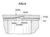
- FIG. 8 is a view taken on line VIII-VIII of FIG. 7.
- FIG. 4 is a view taken on line IV-IV of FIG. 7.
- the valve plate 3(5) which is generally disk-shaped, is formed therethrough with refrigerant outlet ports 3a(5a) via which refrigerant gas is delivered from the compression chambers 21(22) to a discharge chamber (high-pressure chamber) 24, relief holes 3b(5b) via each of which a suction valve element 27d(28d), referred to hereinbelow, opens toward a corresponding one of the compression chambers 21(22) during each suction stroke, and through holes 3c(5c) through which bolts, not shown, extend, respectively.
- the valve plate 3(5) is formed of a hot rolled steel (SPHC) or the like.
- Each of the relief holes 3b(5b) opens toward a corresponding one of the compression chambers 21(22), for communicating between the compression chamber 21(22) and a corresponding one of refrigerant inlet ports 29d(30d), referred to hereinafter, when a corresponding suction valve element 27d(28d) opens.
- the valve plate 3(5) is formed therethrough with rivet holes 3d(5d) each opposed in a direction of thickness of the valve plate 3(5) (in a vertical direction as viewed in FIG. 4) to a corresponding one of rivet holes 27f(28f) formed through fastening portions 27e(28e) of the valve sheet 27(28), referred to hereinbelow.
- the valve sheet 27(28) which is generally disk-shaped, has discharge valve elements 27a(28a) and the suction valve elements 27d(28d) each cut into a tongue shape, and through holes 27c(28c) through which the bolts extend, respectively.
- the valve sheet 27(28) is formed e.g. of a leaf spring material. As shown in FIGS. 6 and 7, each of the discharge valve elements 27a(28a) and a corresponding one of the suction valve elements 27d(28d) are formed in a manner parallel to each other along length thereof with the fastening portion 27e(28e) formed therebetween.
- Each of the fastening portions 27e(28e) is formed therethrough with the rivet hole 27f(28f) through which a rivet 50(51) extends.
- the stopper plate 29(30) which is generally disk-shaped, is formed therein with stopper portions 29a(30a). Each of the stopper portions 29a(30a) is formed by a tongue-shaped recess opposed to a corresponding one of the tongue-shaped discharge valve elements 27a(28a).
- the stopper plate 29(30) is also formed with the refrigerant inlet ports 29d(30d) via which refrigerant gas is drawn from a suction chamber (low-pressure chamber) 23 into the compression chambers 21(22).
- the stopper plate 29(30) is formed of aluminum alloy, a hot rolled steel (SPHC) or the like. As shown in FIG.
- each stopper portion 29a(30a) has a bottom surface which is inclined at a predetermined angle with respect to a corresponding one of the discharge valve elements 27a(28a) in a valve-closing position or sloped at a predetermined curvature, thereby setting a proper limit to an amount of opening or resilient deformation of the discharge valve element 27a(28a).
- FIG. 8 shows the discharge valve element 27a(28a) in a valve-opening position.
- the stopper plate 29(30) also has slots (refrigerant outlet passage) 29b(30b) formed therethrough along length of the stopper portions 29a(30a).
- Each of the slots 29b(30b) is open to the discharge chamber 24 for communicating between the discharge chamber 24 and a corresponding one of the refrigerant outlet ports 3a(5a) when a corresponding one of the discharge valve elements 27a(28a) opens.
- the stopper plate 29(30) is formed therethrough with rivet holes 29e(30e) each opposed in the direction of thickness of the valve plate 3(5) (in the vertical direction as viewed in FIG. 4) to a corresponding one of the rivet holes 27f(28f) each formed through the fastening portion 27e(28e) of the valve sheet 27(28).
- Each rivet (fastening means) 50(51) is inserted through the rivet holes 3d(5d), 27f(28f), and 29e(30e) formed respectively through the valve plate 3(5), the valve sheet 27(28), and the stopper plate 29(30), and then caulked to join the valve plate 3(5), the valve sheet 27(28), and the stopper plate 29(30) to each other to form a unit.
- motions of the valve plate 3(5) in a direction of thickness of the fastening portions 27e(28e) i.e. in the vertical direction as viewed in FIG. 4) and in a radial direction (rightward and leftward direction as viewed in FIG. 4) are restrained.
- Each of the discharge valve elements 27a(28a) is opposed to a corresponding one of the refrigerant outlet ports 3a(5a) formed through the valve plate 3(5) (see FIG. 8), and when the discharge valve element 27a(28a) opens, a corresponding one of the compression chambers 21(22) communicates with the discharge chamber 24 via a corresponding one of the refrigerant outlet ports 3a(5a) and a corresponding one of the slots 29b(30b) formed through the stopper plate 29(30).
- each of the suction valve elements 27d(28d) is opposed to a corresponding one of the refrigerant inlet ports 29d(30d) formed through the stopper plate 29(30), and when the suction valve element 27d(28d) opens, a corresponding one of the compression chambers 21(22) communicates with the suction chamber 23 via a corresponding one of the refrigerant inlet ports 29d(30d) and a corresponding one of the relief holes 3b(5b).
- the swash plate 8 As the drive shaft 7 rotates, the swash plate 8 is rotated in unison therewith. According to the rotation of the swash plate 8, the piston 12 reciprocates within the cylinder bore 11.
- the piston 12 slides to a position shown in FIG. 5 (right-side extremity position in FIG. 5), whereby the suction stroke is completed in the compression chamber 21, while the compression stroke is completed in the compression chamber 22.
- the suction stroke is completed in the compression chamber 22, while the compression stroke is completed in the compression chamber 21.
- the suction valve element 27d(28d) is resiliently deformed or bent toward a corresponding one of the relief holes 3b(5b), whereby a corresponding one of the refrigerant inlet ports 29d(30d) opens, and low-pressure refrigerant gas flows from the suction chamber 23 into the compression chamber 21(22) via the refrigerant inlet port 29d(30d) and the relief hole 3b(5b).
- valve plate 3(5) and the stopper plate 29(30) are joined to each other by the rivets 50(51) via the fastening portions 27e(28e) of the valve sheet 27(28), deformation or distortion of the valve plate 3(5) is inhibited or suppressed, and hence high-pressure gas is prevented from flowing back from the discharge chamber 24 to the compression chamber 21(22).
- the discharge valve element 27a(28a) is resiliently deformed or bent toward the discharge chamber 24, whereby high-pressure refrigerant gas is delivered from the compression chamber 21(22) to the discharge chamber 24.
- the discharge valve element 27a(28a) abuts the bottom surface 42(43) of a corresponding one of the stopper portions 29a(30a), whereby the amount of opening or resilient deformation of the discharge valve element 27a(28a) is controlled.
- the swash plate compressor of the first embodiment it is possible to prevent a back flow of refrigerant gas from the discharge chamber 24 into the compression chamber 21(22) without increasing the thickness of the valve plate 3(5), so that an increase in dead volume within the compressor, which causes degradation of volumetric efficiency, can also be prevented.
- valve plate 3(5), the valve sheet 27(28), and the stopper plate 29(30) are joined to each other to form a unit, the three components 3(5), 27(28), 29(30) can be mounted in the compressor as the unit, which further facilitates assembly of the compressor in comparison with the conventional method in which the components 3(5), 27(28), 29(30) are mounted separately.
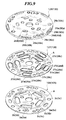
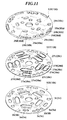
- FIG. 9 shows a valve plate, a valve sheet, and a stopper plate of a swash plate compressor according to a second embodiment of the invention, in an exploded state
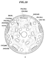
- FIG. 10 is a plan view of the stopper plate in a state in which the valve plate, the valve sheet, and the stopper plate are assembled.
- Component parts and elements corresponding to those of the above embodiment are indicated by identical reference numerals, and description thereof is omitted.
- the second embodiment is distinguished from the first embodiment in which the rivets 50, 51 are used as fastening means, in that an adhesive A is used as fastening means. More specifically, as shown in FIGS. 9 and 10, the adhesive A is annularly applied to a stopper plate-side surface of the valve sheet 127(128) and a valve plate-side surface of the valve plate 103(105) to join the stopper plate 129(130), the valve sheet 127(128), and the valve plate 103(105) to each other to form a unit. In the present embodiment, the adhesive A is applied to an annular portion including all of the five fastening portions 27e(28e) of the valve sheet 127(128).
- annular adhesive portion formed by the adhesive A applied to the valve sheet 127(128) and an annular adhesive portion formed by the adhesive A applied to the valve plate 103(105) are formed at locations corresponding to each other in the direction of thickness of the valve plate 103(105).
- the second embodiment can provide the same effects as obtained by the first embodiment. Further, since the valve plate 103(105) is not required to be formed with any through holes or slots through which fastening members extend respectively, the rigidity of the plate 103(105) is not decreased. Moreover, it is not required to carry out machining for forming relief grooves or the like on the piston 12 within each cylinder bore 11, which enhances manufacturability or productivity of the compressor.
- FIG. 11 shows a valve plate, a valve sheet, and a stopper plate of a swash plate compressor according to a third embodiment of the invention, in an exploded state
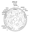
- FIG. 12 is a plan view of the stopper plate in a state in which the valve plate, the valve sheet, and the stopper plate are assembled.
- Component parts and elements corresponding to those of the first embodiment are indicated by identical reference numerals, and description thereof is omitted.
- the third embodiment is distinguished from the second embodiment in which the adhesive A is applied to the surfaces of the valve sheet 127(128) and the valve plate 103(105) to form the annular adhesive portions thereon, respectively, in that the adhesive A is applied separately to a plurality of predetermined portions of the valve sheet 127(128) and the valve plate 103(105), i.e. to the fastening portions 27e(28e) of the valve sheet 127(128) and predetermined portions (portions each corresponding to a corresponding one of the fastening portions 27e(28e) of the valve sheet 127(128)) of the valve plate 103(105). As shown in FIG.
- each of the separate adhesive portions formed by the adhesive A on the fastening portions 27e(28e) of the valve sheet 127(128) and the predetermined portions of the valve plate 103(105) is located radially inside of a corresponding one of the cylinder bores 11.
- the third embodiment can provide the same effects as obtained by the second embodiment.
Landscapes
- Engineering & Computer Science (AREA)
- Mechanical Engineering (AREA)
- General Engineering & Computer Science (AREA)
- Compressors, Vaccum Pumps And Other Relevant Systems (AREA)
- Compressor (AREA)
Applications Claiming Priority (3)
| Application Number | Priority Date | Filing Date | Title |
|---|---|---|---|
| JP11885597 | 1997-04-22 | ||
| JP118855/97 | 1997-04-22 | ||
| JP9118855A JPH10299657A (ja) | 1997-04-22 | 1997-04-22 | 往復式圧縮機 |
Publications (2)
| Publication Number | Publication Date |
|---|---|
| EP0874156A2 true EP0874156A2 (de) | 1998-10-28 |
| EP0874156A3 EP0874156A3 (de) | 2000-08-02 |
Family
ID=14746815
Family Applications (1)
| Application Number | Title | Priority Date | Filing Date |
|---|---|---|---|
| EP98303118A Withdrawn EP0874156A3 (de) | 1997-04-22 | 1998-04-22 | Verdrängerverdichter |
Country Status (3)
| Country | Link |
|---|---|
| EP (1) | EP0874156A3 (de) |
| JP (1) | JPH10299657A (de) |
| CN (1) | CN1197163A (de) |
Cited By (1)
| Publication number | Priority date | Publication date | Assignee | Title |
|---|---|---|---|---|
| CN118499222A (zh) * | 2024-07-17 | 2024-08-16 | 江苏嘉实石化设备有限公司 | 一种网状阀片及其阀门组件 |
Families Citing this family (2)
| Publication number | Priority date | Publication date | Assignee | Title |
|---|---|---|---|---|
| JP2011231733A (ja) * | 2010-04-30 | 2011-11-17 | Hitachi Appliances Inc | 密閉型圧縮機 |
| CN103671079B (zh) * | 2013-10-25 | 2016-02-03 | 厦门科际精密器材有限公司 | 一种气密性改良型气泵 |
Citations (1)
| Publication number | Priority date | Publication date | Assignee | Title |
|---|---|---|---|---|
| JPH094563A (ja) | 1995-04-18 | 1997-01-07 | Zexel Corp | 往復式圧縮機 |
Family Cites Families (1)
| Publication number | Priority date | Publication date | Assignee | Title |
|---|---|---|---|---|
| US3458114A (en) * | 1967-03-13 | 1969-07-29 | Champion Pneumatic Machinery C | Compressor |
-
1997
- 1997-04-22 JP JP9118855A patent/JPH10299657A/ja not_active Withdrawn
-
1998
- 1998-04-22 EP EP98303118A patent/EP0874156A3/de not_active Withdrawn
- 1998-04-22 CN CN 98107319 patent/CN1197163A/zh active Pending
Patent Citations (2)
| Publication number | Priority date | Publication date | Assignee | Title |
|---|---|---|---|---|
| JPH094563A (ja) | 1995-04-18 | 1997-01-07 | Zexel Corp | 往復式圧縮機 |
| US5709535A (en) | 1995-04-18 | 1998-01-20 | Zexel Corporation | Multi-cylinder reciprocating compressor having improved discharge valve stopper assembly |
Cited By (1)
| Publication number | Priority date | Publication date | Assignee | Title |
|---|---|---|---|---|
| CN118499222A (zh) * | 2024-07-17 | 2024-08-16 | 江苏嘉实石化设备有限公司 | 一种网状阀片及其阀门组件 |
Also Published As
| Publication number | Publication date |
|---|---|
| CN1197163A (zh) | 1998-10-28 |
| EP0874156A3 (de) | 2000-08-02 |
| JPH10299657A (ja) | 1998-11-10 |
Similar Documents
| Publication | Publication Date | Title |
|---|---|---|
| EP0874155A2 (de) | Verdrängerverdichter | |
| EP1953385B1 (de) | Taumelscheibenverdichter | |
| US6139282A (en) | Variable capacity refrigerant compressor with an aluminum cam plate means | |
| JP4096703B2 (ja) | ピストン式圧縮機における冷媒吸入構造 | |
| US5709535A (en) | Multi-cylinder reciprocating compressor having improved discharge valve stopper assembly | |
| US7004734B2 (en) | Reciprocating refrigerant compressor | |
| EP0874156A2 (de) | Verdrängerverdichter | |
| EP0881386B1 (de) | Schiebscheibenverdichter | |
| US6174147B1 (en) | Refrigerant compressor with an improved discharge valve assembly | |
| EP1092872B1 (de) | Kolben für Taumelscheibenverdichter | |
| JPH10266965A (ja) | 往復動型圧縮機 | |
| JP3985507B2 (ja) | 斜板型圧縮機 | |
| JP5273504B2 (ja) | 圧縮機 | |
| EP0263576B1 (de) | Kompressor mit Auslassventil | |
| JPH1182302A (ja) | 往復式圧縮機 | |
| US20040194209A1 (en) | Piston compressor | |
| EP1571336A2 (de) | Kolbenverdichter | |
| JP2004183609A (ja) | 回転機械の調整方法 | |
| JP4304544B2 (ja) | ピストン式圧縮機における冷媒吸入構造 | |
| JPH10196542A (ja) | 往復式圧縮機 | |
| US20050058561A1 (en) | Compressor | |
| JP7160001B2 (ja) | ピストン式圧縮機 | |
| JP2002349440A (ja) | 往復式冷媒圧縮機 | |
| KR20150060199A (ko) | 왕복식 압축기 | |
| JP3079743B2 (ja) | ピストン型圧縮機における冷媒ガス吸入構造 |
Legal Events
| Date | Code | Title | Description |
|---|---|---|---|
| PUAI | Public reference made under article 153(3) epc to a published international application that has entered the european phase |
Free format text: ORIGINAL CODE: 0009012 |
|
| AK | Designated contracting states |
Kind code of ref document: A2 Designated state(s): DE FR GB SE |
|
| AX | Request for extension of the european patent |
Free format text: AL;LT;LV;MK;RO;SI |
|
| PUAL | Search report despatched |
Free format text: ORIGINAL CODE: 0009013 |
|
| AK | Designated contracting states |
Kind code of ref document: A3 Designated state(s): AT BE CH CY DE DK ES FI FR GB GR IE IT LI LU MC NL PT SE |
|
| AX | Request for extension of the european patent |
Free format text: AL;LT;LV;MK;RO;SI |
|
| RIC1 | Information provided on ipc code assigned before grant |
Free format text: 7F 04B 39/10 A, 7F 04B 27/10 B |
|
| STAA | Information on the status of an ep patent application or granted ep patent |
Free format text: STATUS: THE APPLICATION IS DEEMED TO BE WITHDRAWN |
|
| AKX | Designation fees paid |
Free format text: DE FR GB SE |
|
| 18D | Application deemed to be withdrawn |
Effective date: 20001101 |