EP0873940A2 - Roll cutting device with a packaging means - Google Patents
Roll cutting device with a packaging means Download PDFInfo
- Publication number
- EP0873940A2 EP0873940A2 EP98106111A EP98106111A EP0873940A2 EP 0873940 A2 EP0873940 A2 EP 0873940A2 EP 98106111 A EP98106111 A EP 98106111A EP 98106111 A EP98106111 A EP 98106111A EP 0873940 A2 EP0873940 A2 EP 0873940A2
- Authority
- EP
- European Patent Office
- Prior art keywords
- packaging
- winding
- partial
- roll
- roller
- Prior art date
- Legal status (The legal status is an assumption and is not a legal conclusion. Google has not performed a legal analysis and makes no representation as to the accuracy of the status listed.)
- Granted
Links
Images


Classifications
-
- B—PERFORMING OPERATIONS; TRANSPORTING
- B65—CONVEYING; PACKING; STORING; HANDLING THIN OR FILAMENTARY MATERIAL
- B65H—HANDLING THIN OR FILAMENTARY MATERIAL, e.g. SHEETS, WEBS, CABLES
- B65H18/00—Winding webs
- B65H18/08—Web-winding mechanisms
-
- B—PERFORMING OPERATIONS; TRANSPORTING
- B65—CONVEYING; PACKING; STORING; HANDLING THIN OR FILAMENTARY MATERIAL
- B65B—MACHINES, APPARATUS OR DEVICES FOR, OR METHODS OF, PACKAGING ARTICLES OR MATERIALS; UNPACKING
- B65B25/00—Packaging other articles presenting special problems
- B65B25/14—Packaging paper or like sheets, envelopes, or newspapers, in flat, folded, or rolled form
- B65B25/146—Packaging paper or like sheets, envelopes, or newspapers, in flat, folded, or rolled form packaging rolled-up articles
- B65B25/148—Jumbo paper rolls
-
- B—PERFORMING OPERATIONS; TRANSPORTING
- B65—CONVEYING; PACKING; STORING; HANDLING THIN OR FILAMENTARY MATERIAL
- B65H—HANDLING THIN OR FILAMENTARY MATERIAL, e.g. SHEETS, WEBS, CABLES
- B65H2301/00—Handling processes for sheets or webs
- B65H2301/40—Type of handling process
- B65H2301/41—Winding, unwinding
- B65H2301/414—Winding
- B65H2301/4148—Winding slitting
Definitions
- the invention relates to a roll cutting device for a material web with a material web feed section, a slitting section and a winding section, the at least one drive device for Has winding of at least one partial roll.
- Such a roll cutting device is under the The name DuoRoller II from Voith Sulzer Paper Machines GmbH, Heidenheim, distributed (company publication “DuoRoller II - The winding concept for graphic papers”).
- the invention is intended to be based on the example of a paper web are explained. But it is the same Can also be used with other material webs are handled in a similar manner.
- Paper webs are commonly used in a paper machine made with a width that is larger than a width that is used in printing plants or other finishing plants can be handled. So can for example paper webs at the end of the paper machine have a width of the order of 10 m, while print shops typically have smaller widths, for example, 0.8 m to 3.8 m.
- the paper web is divided into several longitudinal strips divided what the slitting section is used for, and wound up in a winding section.
- the paper web can either be handled from a roll or directly from another processing station come, for example a calender.
- the manufacture of the partial rolls is usually one the last steps before the paper roll is "finished", so handed over to processing companies becomes. After the partial rolls have been produced usually the packaging of the partial rolls.
- the Packaging serves, among other things, to protect the roll from damage to protect.
- the packaging is often done in that a packaging line around the circumference of the sub-roll, the packaging web applied in one or more layers can be.
- the packaging line often axially over the end faces of the rollers.
- the packaging is then used to help these end faces closed by so-called end covers, on which the The supernatant can be folded in.
- DE-PS 251 396 describes a device for packaging of fabric rolls that have a first changing bed with two driven by a common drive belt Has support rollers in which a roll of fabric is wound becomes.
- the back roller in the direction of travel forms together with another support roller Changing bed that has its own drive.
- the finished wound fabric rolls can be used as a further changing bed be packed.
- DE-OS 20 02 725 describes a method and a device for cross cutting, wrapping and banding long sections of paper or film material.
- the material web is wound in a winding station, in which several rollers are arranged so that the winding roll to be wound in the circumferential direction surrounded different positions.
- This changing station is via a transport route that consists of two in parallel band groups led to each other, with a Packing station connected.
- the changing station is here arranged so that the winding roll when Keeps so that it does not stick with the tapes Conveyor belt groups come into contact.
- the conveyor belt groups are controlled in terms of speed that the finished winding roll with decreasing speed is transported to the packing station but can no longer wind up here.
- the invention is based, the cost to keep low.
- This task is done with a slitter rewinder of the type mentioned in that Winding section at least the circumference of the partial roll packing packaging device is arranged, the the drive device for packaging the partial roll uses.
- the packaging device preferably has at least a packaging web dispenser in parallel is movable to the winding axis. With the packaging web dispenser can then be added one after the other Pack the partial rolls. This is especially true of Advantage when processing partial rolls with changing widths will.
- the partial roles can then on different axial positions can be arranged without that one has to take into account that there too Packaging lane must be present.
- the packaging line is rather provided where the sub-role has been generated.
- the packaging web dispenser to a position outside the sub-roll is movable.
- the partial roles are usually sideways, i.e. across the winding axis, from the winding station pushed out. If you look at the packaging web dispenser for example so far laterally in the axial direction can move that it is outside the web width stands, then there is the possibility of side ejection receive. The packaging web dispenser is annoying not further.
- the packaging web dispenser is preferably opposite the winding axis is pivotable and is also during manufacture the circumferential packaging parallel to the winding axis movable.
- a peripheral packaging generated which is like a helix around the individual sub-roles.
- This approach is currently in connection with a winder of considerable advantage. In such a Roll cutters are usually web rolls generated with changing widths.
- you uses a packaging dispenser that has a creates helical packaging then you are no longer relying on the fact that a large number of Packaging lanes with the correct width for each Has available. You can have a single packaging line use with a fixed width.
- This width can be relatively narrow. It is often sufficient if the Width is in the range of 30 to 80 cm. The necessary The axial length of the peripheral packaging then results automatically when producing the peripheral packaging. If an axially longer part roll is packed are flat correspondingly more revolutions of the partial roller necessary, to create the peripheral packaging.
- the winding section advantageously has two winding position groups on, with the winding axes of the winding positions in a winding position group essentially are the same, the winding axes of both winding position groups are offset against each other and the partial roles in each of the two winding position groups are arranged to each other, for each winding position group a packaging web dispenser is provided. If you have a parent role or one upstream Processing device coming material web divided into several sub-roles, it is advantageous if you do not immediately see the individual sub-roles coiled next to each other, but separately. For this purpose it is known to have two (or more) winding positions to be provided whose winding axes do not match. If you now for each of these winding position groups its own packaging web dispenser then the packaging process can be accelerated. The packing times can be practically on be reduced by half.
- the packaging web dispenser preferably has an adhesive mediator and a guide device on which the packaging web with its tackified Side of the sub-roll feeds. You can count on this Way to ensure that the packaging web on the circumference adheres to the part roll to be packed. If the part role then continues to rotate, then it pulls automatically their packaging web and wraps it on yourself at the same time. Here you can continue Apply glue. In many cases, however, it is enough even if the glue reappears at the end of the packaging process is applied. To make you sticky you can choose other options. So you can for example, use a packaging line that already coated with a water-soluble adhesive is, which then only needs to be moistened. Also Packaging webs coated with a hot melt adhesive are possible if the adhesive mediation device the corresponding supply of heat is guaranteed.
- the guide device advantageously has one Guide path on the circumference of the sub-role in front of a Installation of the partial roll on a roller ends.
- the packaging line can then be sent to the Extent of the sub-role to be performed on a Position where, when the reel turns, a short time later got into a gap between roller and roller.
- There the packaging line is attached to the circumference of the partial roll pressed. This way you can be right achieve good adhesive results so that the packaging web is firmly glued to the circumference of the partial roll, at least at the beginning of the packaging process.
- the guide path has a guide surface in which the distance of their End of the roller is changeable.
- the packaging web it is often necessary that one the packaging web as close as possible to the circumference the sub-role brings. During the packaging process could interfere with the guide surface, however, in particular when the packaging web dispenser is being manufactured Move the peripheral packaging parallel to the axis becomes. If you pull back the end of the guide surface, thus the distance of the guide surface from the Partial roll or the roller enlarged, then the packaging process through the guide surface no longer with special needs.
- the winding station is advantageous in the area of a machine frame arranged, and the packaging device is hung on the machine frame.
- a machine frame is at many slitter winding stations available anyway. You can now take advantage of it Position packaging device.
- the vertical position the packaging device is changeable.
- Man can the packaging device for example lift when the packaged partial rolls are ejected should be.
- the partial roll is preferably located during winding and packaging on two rollers.
- a roller as Drive roller may be formed while the other only serves as a support or support roller.
- the packaging line can be arranged with little effort between the roll to be packed and Insert one of the two rollers so that it immediately following the wrapping process, the peripheral packaging can be made.
- the partial role rest on a roller with a roller core holding device is arranged above the roller.
- the Roll core holding device is at the beginning of the winding process often pushed towards the roller, so that the roller can form a peripheral drive.
- With increasing roll diameter increases weight the partial roll so that the roll core holding device only has to assume holding functions.
- Even with one the circumferential packaging can be configured in this way easy to manufacture by having the packaging web into the gap between the roller and roller.
- one spreader is arranged, and several Partial rollers are spaced apart in the Arranged winding device, one between the Partially retractable knife device provided is.
- the material web spread after cutting i.e. the individual tracks are guided so that they are in the winding device have a predetermined distance from each other. Of the The distance is usually a few centimeters.
- you can then after finishing the Partial rolls a helical circumferential package the whole of the partial rolls. This is possible, because all sub-roles are usually the same Have diameter.
- the knife device After making the peripheral packaging is then using the knife device a separation between the individual, packaged partial rolls made so that the partial roles again individually become manageable.
- the knife device is preferably parallel movable to the winding axis. This also allows different Handle the widths of the partial rolls.
- the Knife device is moved where there is a separation necessary is. Here you can separate the individual Carry out partial roles one after the other.
- the Knife setup only needs one point of circumference can act. A circumferential cut is then made by rotating the roller.
- a roll cutting device 1 has a feed section 2, in which a material web 3 of the device is fed.
- the material web 3 can do this be handled by a jumbo or parent roll. But you can also directly from a calender or other post-processing facility. This is generally known and is therefore not explained further.
- the material web 3 then runs through a slitting section 4, in which a cutting device 5 is arranged is.
- the cutting device 5 divides the material web 3 in several lying side by side in the transverse direction Material web sections, the width of this Material web sections, also called partial webs to the needs of the customers of the material web is adjusted. If the original web of material 3, for example, a width in the range from 6 to 10 m has, then the partial webs have a width in the Of the order of 0.8 to 3.8 m.
- the cutting devices 5 are adjustable in the transverse direction, so that different patterns can be created, the original material web 3 in several sub-webs with different and changing widths can be divided.
- a central roller 8 is provided in the winding section, which rotates in the direction of an arrow 9.
- the central roller 8 is here from the material web 3 or whose partial webs are looped over a larger angular range.
- the partial rollers 7 are interposed the material web 3 on the central roller 8.
- Your Roll cores 10 are mounted on levers 11, which on a stationary base 12, for example, in a not be attached to the machine frame shown can be pivoted.
- the partial web rolls 7th are divided into two winding positions.
- the presentation 2 are two web rolls left of the central roller 8 and a partial web roll 7 to the right of the central roller 8 arranged.
- Winding position group in the present embodiment is occupied with two partial rollers 7, while the right winding position group only occupied with one roll is.
- the roles are mutually spaced, so that they are wrapped without interference can be.
- the winding axes in a wikicle position group are on a line. Of the Roll construction takes place in the same way for all partial rolls 7.
- each packaging web dispenser 14 carries a packaging web roll 15. Die Width of the packaging web roll 15 is significantly smaller than the width of the sub-rolls 7. The width of the Packaging web roll 15 moves in the range of 0.3 up to 0.8 m.
- Each packaging web dispenser 14 has a guide surface 16 on which the from the packaging web roll 15 deducted packaging web 17 to the extent of a Partial roller 7 can be advanced. Still is a glue application device 18 is provided which the Part roll 7 facing side of the packaging web 17 can apply an adhesive.
- the leadership area 16 can be advanced in the direction of the partial roller 7 a gap between the guide surface 16 and the surface to keep the partial roller 7 as small as possible. she is also retractable so that the packaging process, which is described below, not is disturbed.
- the packaging web dispenser 14 adjustable in angle, i.e. the output Packing lane 17 will when it is on the partial roll 7 comes to the system and sticks there when turning the partial roller 7 is not pulled exactly in the circumferential direction, but it wraps around in a spiral the web roll 7 around.
- the Packaging web dispenser 14 in the direction of the double arrow 19. Of course he only moves into one when wrapping Direction.
- the direction i.e. up or down in Fig. 2, determines which angle the Packaging web dispenser 14 taken for part roll 7 Has.
- the individual sub-rollers 7 can thus in each wikenspositions mich one after the other with an extensive package be provided. But it is also possible to have multiple packaging web dispensers 14 to be provided per winding position group to speed up the packaging process.
- the packaging web dispenser 14 is on the right axially movable into a position 20, which is shown in FIG is shown in dashed lines. Located in this position he's definitely outside the breadth of the Material web 3 so that the partial rolls 7 are ejected laterally can be without the packaging web donor 14 to be hindered. If the partial rolls 7 the roll cutting device Leave 1, then at least they are on its scope already with packaging provided and thus against mechanical damage largely protected. Because packaging is immediate following the completion of the partial rolls, can considerable time savings can be achieved here. Since the Packaging device integrated in the winding device saves installation space.
- FIG. 3 and 4 show another embodiment of a Roll cutting device with the same parts are provided with the same reference numerals.
- the partial rollers 7 are now on two rollers 21, 22 stored, of which the roller 21 in the direction of the arrow 9 is driven.
- the packaging web 17 is in the area between the other roller 22 and the sub-roller 7 introduced. There it adheres to the peripheral surface the sub-roll 7, if previously with the help of Glue application device 18 adhesive has been applied is.
- FIG. 5 and 6 show a third embodiment of a Roll cutting device. The same parts are the same Provide reference numerals.
- two are again different Winding position groups provided on both sides of a central roller 8 are arranged.
- the Sub-rollers 7 are also each on one Carrier roller 22 on.
- FIGS. 5 and 6 show the arrangement according to FIGS. 5 and 6 schematically, to represent where the packaging web dispenser are arranged.
- a machine frame 24 provided the four pillars 25, on both ends one longitudinal cross member 27 and each in the transverse direction has a crossbar 26.
- the crossbeams 26 can only be seen in section.
- a carriage 27 displaceable in the transverse direction which the packaging web dispenser 14 depends on.
- the connection between the packaging web dispenser 14 and the carriage 28 takes place via a piston-cylinder unit 29, with the help of the packaging web dispenser 14 so far can be raised that the partial rollers 7 on the right side of the central roller 8 ejected to the right can be without using the packaging web dispenser to collide.
- the guide surface 16 must withdrawn far that an upward movement the partial roll 7 is possible.
Abstract
Description
Die Erfindung betrifft eine Rollenschneidevorrichtung für eine Materialbahn mit einem Materialbahnzuführabschnitt, einem Längsschneideabschnitt und einem Wickelabschnitt, der mindestens eine Antriebseinrichtung zum Wickeln von mindestens einer Teilrolle aufweist.The invention relates to a roll cutting device for a material web with a material web feed section, a slitting section and a winding section, the at least one drive device for Has winding of at least one partial roll.
Eine derartige Rollenschneidevorrichtung wird unter dem Namen DuoRoller II von der Voith Sulzer Papiermaschinen GmbH, Heidenheim, vertrieben (Firmendruckschrift "DuoRoller II - The winding concept for graphic papers").Such a roll cutting device is under the The name DuoRoller II from Voith Sulzer Paper Machines GmbH, Heidenheim, distributed (company publication "DuoRoller II - The winding concept for graphic papers").
Die Erfindung soll nachfolgend am Beispiel einer Papierbahn erläutert werden. Sie ist aber in gleicher Weise auch bei anderen Materialbahnen verwendbar, die auf ähnliche Weise gehandhabt werden.The invention is intended to be based on the example of a paper web are explained. But it is the same Can also be used with other material webs are handled in a similar manner.
Papierbahnen werden in einer Papiermaschine üblicherweise mit einer Breite gefertigt, die größer ist als eine Breite, die in Druckereien oder anderen Weiterverarbeitungsbetrieben gehandhabt werden kann. So können beispielsweise Papierbahnen am Ende der Papiermaschine eine Breite in der Größenordnung von 10 m aufweisen, während Druckereien üblicherweise geringere Breiten, beispielsweise 0,8 m bis 3,8 m, verarbeiten. Aus diesem Grunde wird die Papierbahn in mehrere Längsstreifen unterteilt, wozu der Längsschneideabschnitt dient, und in einem Wickelabschnitt aufgewickelt. Die Papierbahn kann hierbei entweder von einer Rolle abgewickelt werden oder direkt von einer anderen Bearbeitungsstation kommen, beispielsweise einem Kalander.Paper webs are commonly used in a paper machine made with a width that is larger than a width that is used in printing plants or other finishing plants can be handled. So can for example paper webs at the end of the paper machine have a width of the order of 10 m, while print shops typically have smaller widths, for example, 0.8 m to 3.8 m. For this Basically, the paper web is divided into several longitudinal strips divided what the slitting section is used for, and wound up in a winding section. The paper web can either be handled from a roll or directly from another processing station come, for example a calender.
Das Herstellen der Teilrollen ist üblicherweise einer der letzten Arbeitsschritte, bevor die Papierrolle "fertig" ist, also an Weiterbearbeitungsbetriebe abgegeben wird. Nach dem Herstellen der Teilrollen erfolgt üblicherweise noch die Verpackung der Teilrollen. Die Verpackung dient unter anderem dazu, die Rolle vor Beschädigung zu schützen.The manufacture of the partial rolls is usually one the last steps before the paper roll is "finished", so handed over to processing companies becomes. After the partial rolls have been produced usually the packaging of the partial rolls. The Packaging serves, among other things, to protect the roll from damage to protect.
Die Verpackung erfolgt vielfach dadurch, daß eine Verpackungsbahn um den Umfang der Teilrolle gelegt wird, wobei die Verpackungsbahn ein- oder mehrlagig aufgebracht werden kann. Hierbei steht die Verpackungsbahn vielfach axial über die Stirnseiten der Rollen über. An diesen Stirnseiten wird die Verpackung dann mit Hilfe von sogenannten Stirndeckeln geschlossen, auf die der Überstand eingefaltet werden kann. Hierzu sind Verpakungsmaschinen bekannt, denen die Teilrollen zugeführt werden. Diese Verpackungsmaschinen oder -anlagen benötigen aber wiederum einen erheblichen Bauraum, was die Kosten beim Bau und beim Unterhalt einer Papierfabrik erhöht. Darüber hinaus erfordert die Verpackungsmaschine ein entsprechendes Bedienungspersonal.The packaging is often done in that a packaging line around the circumference of the sub-roll, the packaging web applied in one or more layers can be. Here is the packaging line often axially over the end faces of the rollers. On The packaging is then used to help these end faces closed by so-called end covers, on which the The supernatant can be folded in. There are packaging machines for this known, which supplied the partial roles will. These packaging machines or lines need but again a significant amount of space, which the Cost of building and maintaining a paper mill elevated. It also requires the packaging machine an appropriate operator.
DE-PS 251 396 beschreibt eine Vorrichtung zum Verpacken von Stoffrollen, die ein erstes Wickelbett mit zwei über einen gemeinsamen Antriebsriemen angetriebene Tragwalzen aufweist, in dem eine Stoffrolle aufgewickelt wird. Die in Laufrichtung hintere Tragwalze bildet zusammen mit einer weiteren Tragwalze ein weiteres Wickelbett, das einen eigenen Antrieb aufweist. In diesem weiteren Wickelbett können die fertig gewickelten-Stoffrollen verpackt werden.DE-PS 251 396 describes a device for packaging of fabric rolls that have a first changing bed with two driven by a common drive belt Has support rollers in which a roll of fabric is wound becomes. The back roller in the direction of travel forms together with another support roller Changing bed that has its own drive. In this The finished wound fabric rolls can be used as a further changing bed be packed.
DE-OS 20 02 725 beschreibt ein Verfahren und eine Vorrichtung zum Querschneiden, Wickeln und Banderolieren langer Bahnabschnitte aus Papier oder Folienmaterial. Hier wird die Materialbahn in einer Wickelstation gewickelt, in der mehrere Walzen so angeordnet sind, daß sie die zu wickelnde Wickelrolle in Umfangsrichtung an unterschiedlichen Positionen umgeben. Diese Wickelstation ist über einen Transportweg, der aus zwei parallel zueinander geführten Bandgruppen besteht, mit einer Verpackungsstation verbunden. Die Wickelstation ist hierbei so angeordnet, daß sie die Wickelrolle beim Wickeln so hält, daß sie nicht mit den Bändern der Transportbandgruppen in Kontakt kommt. Die Transportbandgruppen werden geschwindigkeitsmäßig so gesteuert, daß die fertige Wickelrolle mit abnehmender Geschwindigkeit zur Verpackungsstation transportiert wird, sich aber hierbei nicht mehr aufwickeln kann.DE-OS 20 02 725 describes a method and a device for cross cutting, wrapping and banding long sections of paper or film material. Here the material web is wound in a winding station, in which several rollers are arranged so that the winding roll to be wound in the circumferential direction surrounded different positions. This changing station is via a transport route that consists of two in parallel band groups led to each other, with a Packing station connected. The changing station is here arranged so that the winding roll when Keeps so that it does not stick with the tapes Conveyor belt groups come into contact. The conveyor belt groups are controlled in terms of speed that the finished winding roll with decreasing speed is transported to the packing station but can no longer wind up here.
Der Erfindung liegt die Aufgabe zugrunde, die Kosten niedrig zu halten.The invention is based, the cost to keep low.
Diese Aufgabe wird bei einer Rollenschneidevorrichtung der eingangs genannten Art dadurch gelöst, daß im Wickelabschnitt eine zumindest den Umfang der Teilrolle verpackende Verpackungseinrichtung angeordnet ist, die die Antriebseinrichtung zum Verpacken der Teilrolle nutzt. This task is done with a slitter rewinder of the type mentioned in that Winding section at least the circumference of the partial roll packing packaging device is arranged, the the drive device for packaging the partial roll uses.
Mit dieser Ausgestaltung erreicht man mehrere Vorteile auf einmal. Zum einen spart man einen teilweise beträchtlichen Bauraum ein, weil die Verpackungseinrichtung zumindest teilweise in den Wickelabschnitt integriert ist. Zumindest die Umfangsverpackung kann also bereits im Wickelabschnitt erzeugt werden. Dies hat den weiteren Vorteil, daß die Rolle bereits ab der Wickelstation zumindest teilweise geschützt ist. Die meisten Transporteinrichtungen greifen am Umfang der Rolle an. Wenn dort bereits eine Umfangsverpackung vorhanden ist, dann wird allenfalls die Umfangsverpackung belastet, nicht jedoch die Papierbahn. Die Stirnseiten können bei einer derartigen Anordnung durchaus später verpackt werden. Zum anderen nutzt man nun einen ohnehin vorhandenen Antrieb, der bislang ausschließlich für das Wikeln der Teilrolle zuständig war, für einen weiteren Zweck. Der Antrieb dreht nämlich die Teilrolle beim Herstellen der Umfangsverpackung. Hierzu ist also kein zusätzlicher Antrieb erforderlich, was sich wiederum günstig auf die Kosten auswirkt. Auch wird Verarbeitungszeit eingespart. Die in dem gesamten Produktionsprozeß notwendigen Zeiten setzen sich üblicherweise aus den eigentlichen Behandlungszeiten und den Zeiten zusammen, die notwendig sind, um die entsprechenden Rollen oder Teilrollen in die einzelnen Bearbeitungsstationen einzuführen bzw. auszuschleusen. Wenn man nun den Übergang zwischen der Wickelstation und der Verpackungsstation einspart, lassen sich die entsprechenden Übergangszeiten einsparen, wodurch sich insgesamt kürzere Behandlungszeiten für die Papierrollen ergeben. Außerdem kann man das Personal an der Verpackungsmaschine einsparen.With this configuration, there are several advantages at once. On the one hand, you save a considerable amount Installation space because the packaging facility at least partially integrated into the winding section is. At least the peripheral packaging can are already generated in the winding section. This has the further advantage that the roll already from the winding station is at least partially protected. Most Transport devices attack the circumference of the roll. If there is already extensive packaging there, then at most the peripheral packaging will be charged, but not the paper web. The end faces can be such an arrangement packed quite later will. On the other hand, you now use an existing one Drive that was previously used only for wiggling the sub-role was responsible for another Purpose. The drive rotates the partial role at Manufacture of the peripheral packaging. So there is none additional drive required, which in turn has a favorable effect on costs. Also processing time saved. That in the whole production process necessary times usually expose themselves the actual treatment times and the times together, which are necessary to the appropriate roles or partial rolls in the individual processing stations introduce or discharge. If you now the transition between the winding station and the packaging station saves, the corresponding Save transition times, which makes overall result in shorter treatment times for the paper rolls. You can also see the staff at the packaging machine save on.
Vorzugsweise weist die Verpackungseinrichtung wenigstens einen Verpackungsbahnspender auf, der parallel zur Wickelachse verfahrbar ist. Mit dem Verpackungsbahnspender lassen sich dann nacheinander einzelne Teilrollen verpaken. Dies ist insbesondere dann von Vorteil, wenn Teilrollen mit wechselnden Breiten verarbeitet werden. Die Teilrollen können dann an unterschiedlichen axialen Positionen angeordnet werden, ohne daß man darauf rücksicht nehmen muß, daß dort auch die Verpackungsbahn vorhanden sein muß. Die Verpackungsbahn wird vielmehr dort bereitgestellt, wo die Teilrolle erzeugt worden ist.The packaging device preferably has at least a packaging web dispenser in parallel is movable to the winding axis. With the packaging web dispenser can then be added one after the other Pack the partial rolls. This is especially true of Advantage when processing partial rolls with changing widths will. The partial roles can then on different axial positions can be arranged without that one has to take into account that there too Packaging lane must be present. The packaging line is rather provided where the sub-role has been generated.
Hierbei ist besonders bevorzugt, daß der Verpackungsbahnspender in eine Position außerhalb der Teilrolle verfahrbar ist. Die Teilrollen werden üblicherweise seitlich, d.h. quer zur Wickelachse, aus der Wickelstation ausgestoßen. Wenn man nun den Verpackungsbahnspender beispielsweise in Axialrichtung so weit seitlich verfahren kann, daß er außerhalb der Materialbahnbreite steht, dann bleibt die Möglichkeit des seitlichen Auswurfs erhalten. Der Verpackungsbahnspender stört also nicht weiter.It is particularly preferred that the packaging web dispenser to a position outside the sub-roll is movable. The partial roles are usually sideways, i.e. across the winding axis, from the winding station pushed out. If you look at the packaging web dispenser for example so far laterally in the axial direction can move that it is outside the web width stands, then there is the possibility of side ejection receive. The packaging web dispenser is annoying not further.
Vorzugsweise ist der Verpackungsbahnspender gegenüber der Wickelachse verschwenkbar und ist auch beim Herstellen der Umfangsverpackung parallel zur Wickelachse verfahrbar. Mit dieser Ausgestaltung wird eine Umfangsverpackung erzeugt, die sich nach Art einer Schraubenlinie um die einzelnen Teilrollen legt. Diese Vorgehensweise ist gerade in Verbindung mit einem Rollenschneider von erheblichem Vorteil. In einem derartigen Rollenschneider werden üblicherweise Materialbahnrollen mit wechselnden Breiten erzeugt. Würde man nun für jede Breite eine entsprechende Verpackungsbahn bereithalten müssen, ergäben sich erhebliche Schwierigkeiten bei der Bevorratung der Verpackungsbahnen. Wenn man hingegen einen Verpackungsbahnspender verwendet, der eine schraubenlinienförmige Verpackung erzeugt, dann ist man nicht mehr darauf angewiesen, daß man eine Vielzahl von Verpackungsbahnen mit der jeweils richtigen Breite zur Verfügung hat. Man kann eine einzelne Verpackungsbahn mit einer festen Breite verwenden. Diese Breite kann relativ schmal sein. Es reicht vielfach aus, wenn die Breite im Bereich von 30 bis 80 cm liegt. Die notwendige axiale Länge der Umfangsverpackung ergibt sich dann beim Herstellen der Umfangsverpackung automatisch. Wenn eine axial längere Teilrolle verpackt wird, sind eben entsprechend mehr Umdrehungen der Teilrolle notwendig, um die Umfangsverpackung zu erzeugen.The packaging web dispenser is preferably opposite the winding axis is pivotable and is also during manufacture the circumferential packaging parallel to the winding axis movable. With this configuration, a peripheral packaging generated, which is like a helix around the individual sub-roles. This approach is currently in connection with a winder of considerable advantage. In such a Roll cutters are usually web rolls generated with changing widths. Would you now for everyone Have a suitable packaging lane ready there would be considerable difficulties in Storage of the packaging lanes. But if you uses a packaging dispenser that has a creates helical packaging, then you are no longer relying on the fact that a large number of Packaging lanes with the correct width for each Has available. You can have a single packaging line use with a fixed width. This width can be relatively narrow. It is often sufficient if the Width is in the range of 30 to 80 cm. The necessary The axial length of the peripheral packaging then results automatically when producing the peripheral packaging. If an axially longer part roll is packed are flat correspondingly more revolutions of the partial roller necessary, to create the peripheral packaging.
Mit Vorteil weist der Wickelabschnitt zwei Wickelpositionsgruppen auf, wobei die Wickelachsen der Wickelpositionen in einer Wickelpositionsgruppe im wesentlichen gleich sind, die Wickelachsen beider Wickelpositionsgruppen gegeneinander versetzt sind und die Teilrollen in den beiden Wickelpositionsgruppen jeweils auf Lücke zueinander angeordnet sind, wobei für jede Wickelpositionsgruppe ein Verpackungsbahnspender vorgesehen ist. Wenn man eine Mutterrolle oder eine von einer vorgeschalteten Bearbeitungseinrichtung kommende Materialbahn in mehrere Teilrollen unterteilt, ist es von Vorteil, wenn man die einzelnen Teilrollen nicht unmittelbar nebeneinander aufwickelt, sondern getrennt voneinander. Hierzu ist es bekannt, zwei (oder mehr) Wickelpositionen vorzusehen, deren Wickelachsen nicht übereinstimmen. Wenn man nun für jede dieser Wickelpositionsgruppen einen eigenen Verpackungsbahnspender vorsieht, dann kann man den Verpackungsvorgang beschleunigen. Die Verpackungszeiten können praktisch auf die Hälfte vermindert werden.The winding section advantageously has two winding position groups on, with the winding axes of the winding positions in a winding position group essentially are the same, the winding axes of both winding position groups are offset against each other and the partial roles in each of the two winding position groups are arranged to each other, for each winding position group a packaging web dispenser is provided. If you have a parent role or one upstream Processing device coming material web divided into several sub-roles, it is advantageous if you do not immediately see the individual sub-roles coiled next to each other, but separately. For this purpose it is known to have two (or more) winding positions to be provided whose winding axes do not match. If you now for each of these winding position groups its own packaging web dispenser then the packaging process can be accelerated. The packing times can be practically on be reduced by half.
Mit Vorteil sind die Teilrollen in beiden Wickelpositionsgruppen durch die gleiche Zentralwalze am Umfang angetrieben. Damit haben alle Teilrollen die gleiche Umfangsgeschwindigkeit, die darüber hinaus mit der Abzugsgeschwindigkeit an der Mutterrolle übereinstimmt. Es ergeben sich damit auf einfache Weise gute Wickelverhältnisse, ohne daß für jede Wickelpositionsgruppe ein eigener Antrieb notwendig ist. The partial rolls in both winding position groups are advantageous by the same central roller on the circumference driven. So all sub-roles have the same Peripheral speed, in addition, with the withdrawal speed on the parent role. This results in good winding conditions in a simple manner, without for each winding position group a separate drive is necessary.
Vorzugsweise weist der Verpackungsbahnspender eine Klebevermittlungseinrichtung und eine Führungseinrichtung auf, die die Verpackungsbahn mit ihrer klebrig gemachten Seite der Teilrolle zuführt. Man kann auf diese Weise dafür sorgen, daß die Verpackungsbahn am Umfang der zu verpackenden Teilrolle anhaftet. Wenn die Teilrolle dann weitergedreht wird, dann zieht sie selbsttätig ihre Verpackungsbahn nach und wickelt diese gleichzeitig auf sich auf. Hierbei kann man weiterhin Klebstoff auftragen. In vielen Fällen reicht es aber auch aus, wenn der Klebstoff erneut am Ende des Verpackungsvorgangs aufgetragen wird. Zum Klebrigmachen kann man auch andere Möglichkeiten wählen. So kann man beispielsweise eine Verpackungsbahn verwenden, die bereits mit einem wasserlöslichen Klebstoff beschichtet ist, der dann lediglich angefeuchtet werden muß. Auch Verpackungsbahnen, die mit einem Heißschmelzkleber beschichtet sind, sind möglich, wenn die Klebevermittlungseinrichtung die entsprechende Wärmezufuhr gewährleistet.The packaging web dispenser preferably has an adhesive mediator and a guide device on which the packaging web with its tackified Side of the sub-roll feeds. You can count on this Way to ensure that the packaging web on the circumference adheres to the part roll to be packed. If the part role then continues to rotate, then it pulls automatically their packaging web and wraps it on yourself at the same time. Here you can continue Apply glue. In many cases, however, it is enough even if the glue reappears at the end of the packaging process is applied. To make you sticky you can choose other options. So you can for example, use a packaging line that already coated with a water-soluble adhesive is, which then only needs to be moistened. Also Packaging webs coated with a hot melt adhesive are possible if the adhesive mediation device the corresponding supply of heat is guaranteed.
Vorteilhafterweise weist die Führungseinrichtung einen Führungspfad auf, der am Umfang der Teilrolle vor einer Anlage der Teilrolle an einer Walze endet. Die Verpakungsbahn kann dann mit Hilfe des Führungspfades an den Umfang der Teilrolle geführt werden, und zwar an einer Position, wo sie, wenn die Rolle sich dreht, kurze Zeit später in einen Spalt zwischen Rolle und Walze gelangt. Dort wird die Verpackungsbahn an den Umfang der Teilrolle angedrückt. Auf diese Weise lassen sich recht gute Haftergebnisse erzielen, so daß die Verpackungsbahn fest mit dem Umfang der Teilrolle verklebt wird, zumindest am Anfang des Verpackungsvorgangs.The guide device advantageously has one Guide path on the circumference of the sub-role in front of a Installation of the partial roll on a roller ends. The packaging line can then be sent to the Extent of the sub-role to be performed on a Position where, when the reel turns, a short time later got into a gap between roller and roller. There the packaging line is attached to the circumference of the partial roll pressed. This way you can be right achieve good adhesive results so that the packaging web is firmly glued to the circumference of the partial roll, at least at the beginning of the packaging process.
Hierbei ist besonders bevorzugt, daß der Führungspfad eine Führungsfläche aufweist, bei der der Abstand ihres Endes von der Walze veränderbar ist. Am Anfang des Verpackungsvorganges ist es vielfach notwendig, daß man die Verpackungsbahn möglichst dicht bis an den Umfang der Teilrolle bringt. Im Verlauf des Verpackungsvorganges könnte die Führungsfläche jedoch stören, insbesondere dann, wenn der Verpackungsbahnspender beim Herstellen der Umfangsverpackung achsparallel verfahren wird. Wenn man nun das Ende der Führungsfläche zurückzieht, also den Abstand der Führungsfläche von der Teilrolle oder der Walze vergrößert, dann wird der Verpackungsvorgang durch die Führungsfläche nicht mehr behindert.It is particularly preferred that the guide path has a guide surface in which the distance of their End of the roller is changeable. At the beginning of the packaging process it is often necessary that one the packaging web as close as possible to the circumference the sub-role brings. During the packaging process could interfere with the guide surface, however, in particular when the packaging web dispenser is being manufactured Move the peripheral packaging parallel to the axis becomes. If you pull back the end of the guide surface, thus the distance of the guide surface from the Partial roll or the roller enlarged, then the packaging process through the guide surface no longer with special needs.
Mit Vorteil ist die Wickelstation im Bereich eines Maschinenrahmens angeordnet, und die Verpackungseinrichtung ist an dem Maschinenrahmen aufgehängt. Ein Maschinenrahmen ist bei vielen Rollenschneide-Wickelstationen ohnehin vorhanden. Man kann ihn nun ausnutzen, um die Verpackungseinrichtung zu positionieren.The winding station is advantageous in the area of a machine frame arranged, and the packaging device is hung on the machine frame. A machine frame is at many slitter winding stations available anyway. You can now take advantage of it Position packaging device.
Hierbei ist besonders bevorzugt, daß die vertikale Position der Verpackungseinrichtung veränderbar ist. Man kann also die Verpackungseinrichtung beispielsweise anheben, wenn die verpackten Teilrollen ausgestoßen werden sollen. Man kann durch ein Anheben oder Absenken der Verpackungseinrichtung, insbesondere des Verpackungsbahnspenders, auch eine günstige Zufuhr der Verpackungsbahn zu den Teilrollen gewährleisten, was beispielsweise im Hinblick auf die Spannung der Verpackungsbahn wünschenswert sein kann.It is particularly preferred that the vertical position the packaging device is changeable. Man can the packaging device for example lift when the packaged partial rolls are ejected should be. One can raise or lower it the packaging facility, in particular the packaging web dispenser, also a cheap supply of Packaging web to the partial rolls ensure what for example with regard to the tension of the packaging web may be desirable.
Vorzugsweise liegt die Teilrolle beim Wickeln und Verpacken auf zwei Walzen auf. Hierbei kann eine Walze als Antriebswalze ausgebildet sein, während die andere lediglich als Stütz- oder Tragwalze dient. Bei einer derartigen Anordnung läßt sich die Verpackungsbahn mit geringem Aufwand zwischen die zu verpackende Rolle und eine der beiden Walzen einführen, so daß sich unmittelbar im Anschluß an den Wickelvorgang die Umfangsverpackung herstellen läßt. The partial roll is preferably located during winding and packaging on two rollers. Here, a roller as Drive roller may be formed while the other only serves as a support or support roller. With such a The packaging line can be arranged with little effort between the roll to be packed and Insert one of the two rollers so that it immediately following the wrapping process, the peripheral packaging can be made.
In einer alternativen Ausgestaltung kann die Teilrolle auf einer Walze aufliegen, wobei eine Rollenkern-Halteeinrichtung oberhalb der Walze angeordnet ist. Die Rollenkernhalteeinrichtung wird zu Beginn des Wickelvorgangs vielfach in Richtung auf die Walze gedrückt, so daß die Walze einen Umfangsantrieb bilden kann. Mit zunehmendem Rollendurchmesser steigt auch das Gewicht der Teilrolle an, so daß die Rollenkernhalteeinrichtung nur noch Haltefunktionen übernehmen muß. Auch bei einer derartigen Ausgestaltung läßt sich die Umfangsverpakung dadurch leicht herstellen, daß man die Verpackungsbahn in den Spalt zwischen Rolle und Walze einführt.In an alternative embodiment, the partial role rest on a roller, with a roller core holding device is arranged above the roller. The Roll core holding device is at the beginning of the winding process often pushed towards the roller, so that the roller can form a peripheral drive. With increasing roll diameter increases weight the partial roll so that the roll core holding device only has to assume holding functions. Even with one the circumferential packaging can be configured in this way easy to manufacture by having the packaging web into the gap between the roller and roller.
In einer bevorzugten Ausgestaltung ist vor der Wickeleinrichtung eine Spreizeinrichtung angeordnet, und mehrere Teilrollen sind mit Abstand zueinander in der Wickeleinrichtung angeordnet, wobei eine zwischen die Teilrollen einfahrbare Messereinrichtung vorgesehen ist. Bei dieser Ausgestaltung wird die Materialbahn nach dem Schneiden gespreizt, d.h. die einzelnen Bahnen werden so geführt, daß sie in der Wickeleinrichtung einen vorbestimmten Abstand zueinander aufweisen. Der Abstand beträgt normalerweise einige Zentimeter. Insbesondere dann, wenn man einen seitlich verfahrbaren und winkelmäßig verstellbaren Verpackungsbahnspender verwendet, kann man dann nach dem Fertigstellen der Teilrollen eine schraubenlinienförmige Umfangsverpakung der Gesamtheit der Teilrollen herstellen. Dies ist möglich, weil alle Teilrollen üblicherweise den gleichen Durchmesser aufweisen. Nach dem Herstellen der Umfangsverpackung wird dann mit Hilfe der Messereinrichtung eine Trennung zwischen den einzelnen, verpackten Teilrollen vorgenommen, so daß die Teilrollen wieder einzeln handhabbar werden.In a preferred embodiment is in front of the winding device one spreader is arranged, and several Partial rollers are spaced apart in the Arranged winding device, one between the Partially retractable knife device provided is. In this configuration, the material web spread after cutting, i.e. the individual tracks are guided so that they are in the winding device have a predetermined distance from each other. Of the The distance is usually a few centimeters. Especially then when you have a sideways movable and angularly adjustable packaging web dispenser used, you can then after finishing the Partial rolls a helical circumferential package the whole of the partial rolls. This is possible, because all sub-roles are usually the same Have diameter. After making the peripheral packaging is then using the knife device a separation between the individual, packaged partial rolls made so that the partial roles again individually become manageable.
Vorzugsweise ist hierbei die Messereinrichtung parallel zur Wickelachse verfahrbar. Damit lassen sich auch unterschiedliche Breiten der Teilrollen handhaben. Die Messereinrichtung wird dort verfahren, wo eine Trennung notwendig ist. Hierbei kann man das Trennen der einzelnen Teilrollen durchaus nacheinander vornehmen. Die Messereinrichtung muß lediglich einen Punkt des Umfangs beaufschlagen können. Ein Umfangsschnitt erfolgt dann dadurch, daß die Rolle gedreht wird.In this case, the knife device is preferably parallel movable to the winding axis. This also allows different Handle the widths of the partial rolls. The Knife device is moved where there is a separation necessary is. Here you can separate the individual Carry out partial roles one after the other. The Knife setup only needs one point of circumference can act. A circumferential cut is then made by rotating the roller.
Die Erfindung wird im folgenden anhand von bevorzugten Ausführungsbeispielen in Verbindung mit der Zeichnung beschrieben. Hierin zeigen:
- Fig. 1
- eine erste Ausführungsform einer Rollenschneidevorrichtung in schematischer Seitenansicht,
- Fig. 2
- die Vorrichtung nach Fig. 1 in schematischer Draufsicht,
- Fig. 3
- eine zweite Ausführungsform einer Rollenschneidevorrichtung in schematischer Seitenansicht,
- Fig. 4
- die Vorrichtung nach Fig. 3 in schematischer Draufsicht,
- Fig. 5
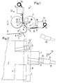
- eine dritte Ausführungsform einer Rollenschneidevorrichtung in schematischer Seitenansicht,
- Fig. 6
- die Vorrichtung nach Fig. 5 in schematischer Draufsicht und
- Fig. 7
- eine Ansicht entsprechend Fig. 5 mit Maschinenrahmen.
- Fig. 1
- a first embodiment of a roll cutting device in a schematic side view,
- Fig. 2
- 1 in a schematic top view,
- Fig. 3
- a second embodiment of a roll cutting device in a schematic side view,
- Fig. 4
- 3 in a schematic top view,
- Fig. 5
- a third embodiment of a roll cutting device in a schematic side view,
- Fig. 6
- 5 in a schematic plan view and
- Fig. 7
- 5 with machine frame.
Eine Rollenschneidevorrichtung 1 weist einen Zufuhrabschnitt
2 auf, in dem eine Materialbahn 3 der Vorrichtung
zugeführt wird. Die Materialbahn 3 kann hierbei
von einer Jumbo- oder Mutterrolle abgewickelt werden.
Sie kann aber auch direkt aus einem Kalander oder einer
anderen Nachbearbeitungseinrichtung stammen. Dies ist
allgemein bekannt und wird deswegen nicht weiter erläutert.A
Die Materialbahn 3 durchläuft dann einen Längsschneideabschnitt
4, in dem eine Schneideinrichtung 5 angeordnet
ist. Die Schneideinrichtung 5 unterteilt die Materialbahn
3 in mehrere in Querrichtung nebeneinanderliegende
Materialbahnabschnitte, wobei die Breite dieser
Materialbahnabschnitte, die auch Teilbahnen genannt
werden, an die Bedürfnisse der Abnehmer der Materialbahn
angepaßt ist. Wenn die ursprüngliche Materialbahn
3 beispielsweise eine Breite im Bereich von 6 bis 10 m
aufweist, dann weisen die Teilbahnen eine Breite in der
Größenordnung von 0,8 bis 3,8 m auf. Die Schneideeinrichtungen
5 sind in Querrichtung verstellbar, so daß
unterschiedliche Schnittmuster erzeugt werden können,
die ursprüngliche Materialbahn 3 also in mehrere Teil-bahnen
mit unterschiedlichen und wechselnden Breiten
unterteilt werden kann.The
Die einzelnen Teilbahnen laufen dann in einen Wickelabschnitt
6, wo sie zu Teilrollen 7 aufgewickelt werden.
Wie aus Fig. 2 ersichtlich ist, können die Teilrollen
durchaus unterschiedliche Breiten aufweisen.The individual partial webs then run into a winding
Im Wickelabschnitt ist eine Zentralwalze 8 vorgesehen,
die sich in Richtung eines Pfeiles 9 dreht. Die Zentralwalze
8 ist hierbei von der Materialbahn 3 bzw.
deren Teilbahnen über einen größeren Winkelbereich umschlungen.
Die Teilrollen 7 liegen unter Zwischenschaltung
der Materialbahn 3 an der Zentralwalze 8 an. Ihre
Rollenkerne 10 sind an Hebeln 11 gelagert, die an einer
stationären Basis 12, die beispielsweise in einem nicht
näher dargestellten Maschinengestell befestigt sein
kann, schwenkbar gelagert sind. A
Wenn sich nun die Zentralwalze 8 dreht, dann werden die
Teilrollen 7 an ihrem Umfang angetrieben und wickeln
die Teilbahnen der Materialbahn 3 auf.If the
Aus Fig. 2 ist ersichtlich, daß die Teilbahnrollen 7
auf zwei Wickelpositionen aufgeteilt sind. Bei der Darstellung
nach Fig. 2 sind zwei Teilbahnrollen links von
der Zentralwalze 8 und eine Teilbahnrolle 7 rechts von
der Zentralwalze 8 angeordnet. Vereinfachend ausgedrückt
befindet sich links von der Zentralwalze 8 eine
Wickelpositionsgruppe, die im vorliegenden Ausführungsbeispiel
mit zwei Teilrollen 7 besetzt ist, während die
rechte Wickelpositionsgruppe nur mit einer Rolle besetzt
ist. Die Rollen sind gegenseitig auf Lücke angeordnet,
so daß sie ohne gegenseitige Beeinflussung gewickelt
werden können. Die Wickelachsen in einer Wikelpositionsgruppe
befinden sich auf einer Linie. Der
Rollenaufbau erfolgt für alle Teilrollen 7 gleichartig.From Fig. 2 it can be seen that the partial web rolls 7th
are divided into two winding positions. In the presentation
2 are two web rolls left of
the
Im Wickelabschnitt befindet sich ferner für jede Wikelpositionsgruppe
eine Verpackungseinrichtung 13 mit
einem Verpackungsbahnspender 14. Jeder Verpackungsbahnspender
14 trägt eine Verpackungsbahnrolle 15. Die
Breite der Verpackungsbahnrolle 15 ist wesentlich geringer
als die Breite der Teilrollen 7. Die Breite der
Verpackungsbahnrolle 15 bewegt sich im Bereich von 0,3
bis 0,8 m.In the winding section there is furthermore for each wikicle position group
a
Jeder Verpackungsbahnspender 14 weist eine Führungsfläche
16 auf, auf der die von der Verpackungsbahnrolle 15
abgezogene Verpackungsbahn 17 bis zum Umfang einer
Teilrolle 7 vorgeschoben werden kann. Weiterhin ist
eine Leimauftragseinrichtung 18 vorgesehen, die die der
Teilrolle 7 zugewandte Seite der Verpackungsbahn 17 mit
einem Klebstoff beaufschlagen kann. Die Führungsfläche
16 ist in Richtung auf die Teilrolle 7 vorschiebbar, um
eine Lücke zwischen der Führungsfläche 16 und der Oberfläche
der Teilrolle 7 möglichst klein zu halten. Sie
ist aber auch wieder zurückziehbar, damit der Verpakungsvorgang,
der im folgenden beschrieben wird, nicht
gestört wird.Each
Wie aus Fig. 2 ersichtlich ist, ist der Verpackungsbahnspender
14 winkelmäßig verstellbar, d.h. die ausgegebene
Verpackungsbahn 17 wird, wenn sie an der Teilrolle
7 zur Anlage kommt und dort festklebt, beim Drehen
der Teilrolle 7 nicht genau in Umfangsrichtung gezogen,
sondern sie legt sich schraubenlinienförmig um
die Materialbahnrolle 7 herum.As can be seen from Fig. 2, the
Während des Drehens der Teilrolle 7 bewegt sich der
Verpackungsbahnspender 14 in Richtung des Doppelpfeiles
19. Natürlich bewegt er sich beim Wickeln nur in eine
Richtung. Die Richtung, also nach oben oder nach unten
in Fig. 2, bestimmt sich danach, welchen Winkel der
Verpackungsbahnspender 14 zur Teilrolle 7 eingenommen
hat.During the rotation of the
Wenn sich die Teilrolle 7 dreht, dann bildet sich, wie
gesagt, eine schraubenlinenförmige Umfangsverpackung,
wobei sich benachbarte Streifen der Verpackungsbahn 17
überlappen können, um eine mehrlagige Umfangsverpackung
herzustellen. Man kann bei diesem Vorgehen mit einer
einzigen Verpackungsbahnbreite beliebig lange Teilrollen
7 verpacken, d.h. man ist nicht darauf angewiesen,
für jede mögliche Teilrollenbreite eine eigene Verpakungsbahn
vorrätig zu halten. Darüber hinaus ist man
sehr flexibel bei der Anordnung der Teilrolle. Man ist
nicht mehr darauf angewiesen, Teilrollen nur dort zu
erzeugen, wo die entsprechende Verpackungsbahn zur Verfügung
steht. Man kann die Teilrollen vielmehr beliebig
aufteilen und fährt dann den Verpackungsbahnspender in
Richtung des Doppelpfeiles an die zu verpackende Teilrolle
7. When the
Die einzelnen Teilrollen 7 können somit in jeder Wikelpositionsgruppe
nacheinander mit einer Umfangsverpakung
versehen werden. Es ist aber auch möglich, mehrere Verpackungsbahnspender
14 pro Wickelpositionsgruppe vorzusehen,
um den Verpackungsvorgang zu beschleunigen.The
Der Verpackungsbahnspender 14 auf der rechten Seite ist
axial in eine Position 20 verfahrbar, die in Fig. 2
gestrichelt dargestellt ist. In dieser Position befindet
er sich auf jeden Fall außerhalb der Breite der
Materialbahn 3, so daß die Teilrollen 7 seitlich ausgestoßen
werden können, ohne vom Verpackungsbahnspender
14 behindert zu werden. Wenn die Teilrollen 7 die Rollenschneidevorrichtung
1 verlassen, dann sind sie zumindest
auf ihrem Umfang bereits mit einer Verpackung
versehen und damit gegen mechanische Beschädigungen
weitgehend geschützt. Da sich das Verpacken unmittelbar
an das Fertigstellen der Teilrollen anschließt, kann
hier ein erheblicher Zeitgewinn erzielt werden. Da die
Verpackungseinrichtung in die Wickeleinrichtung integriert
ist, spart man Bauraum.The
Die Fig. 3 und 4 zeigen eine andere Ausgestaltung einer Rollenschneidevorrichtung, bei der gleiche Teile mit gleichen Bezugszeichen versehen sind.3 and 4 show another embodiment of a Roll cutting device with the same parts are provided with the same reference numerals.
Im Gegensatz zu der Vorrichtung nach den Fig. 1 und 2
werden nun alle Teilrollen 7 nebeneinanderliegend gewickelt.
Hierzu sind in nicht näher dargestellter Weise
Spreizwalzen vorgesehen, die eine Bahnführung erzeugen,
bei der die Teilrollen 7 einen kleinen Abstand A zueinander
aufweisen.In contrast to the device according to FIGS. 1 and 2
all
Die Teilrollen 7 sind nunmehr auf zwei Walzen 21, 22
gelagert, von denen die Walze 21 in Richtung des Pfeiles
9 angetrieben ist. Die Verpackungsbahn 17 wird in
den Bereich zwischen der anderen Walze 22 und der Teilrolle
7 eingeführt. Dort haftet sie dann an der Umfangsfläche
der Teilrolle 7, wenn zuvor mit Hilfe der
Leimauftragseinrichtung 18 Klebstoff aufgetragen worden
ist.The
Bei dieser Ausgestaltung kann man nun die nebeneinanderliegenden
Teilrollen 17 in einem einzigen Verpackungsvorgang
mit Hilfe des Verpackungsbahnspenders
14 verpacken, der dazu über die gesamte Breite, d.h.
über die Summe der Breiten der Teilrollen 7 mit Lücken
verfahren wird. Hierbei entsteht dann eine zusammenhängende
Verpackung, die mit Hilfe eines Messers 23, das
parallel zur Wickelachse und senkrecht dazu verfahren
werden kann, wieder in einzelne Teilrollenabschnitte
aufgeteilt werden kann.In this configuration, you can now the side by side
Fig. 5 und 6 zeigen eine dritte Ausgestaltung einer Rollenschneidevorrichtung. Gleiche Teile sind mit gleichen Bezugszeichen versehen.5 and 6 show a third embodiment of a Roll cutting device. The same parts are the same Provide reference numerals.
Bei dieser Ausführungsform sind wiederum zwei unterschiedliche
Wickelpositionsgruppen vorgesehen, die auf
beiden Seiten einer Zentralwalze 8 angeordnet sind. Die
Teilrollen 7 liegen hierbei zusätzlich jeweils auf einer
Tragwalze 22 auf.In this embodiment, two are again different
Winding position groups provided on
both sides of a
Fig. 7 zeigt die Anordnung nach Fig. 5 und 6 schematisch,
um darzustellen, wo die Verpackungsbahnspender
angeordnet sind. Hierzu ist ein Maschinengestell 24
vorgesehen, das vier Säulen 25, an beiden Stirnseiten
jeweils eine Längstraverse 27 und in Querrichtung jeweils
eine Quertraverse 26 aufweist. Die Quertraversen
26 sind nur im Schnitt zu erkennen.7 shows the arrangement according to FIGS. 5 and 6 schematically,
to represent where the packaging web dispenser
are arranged. For this purpose, there is a
An der in Fig. 7 rechts dargestellten Quertraverse 26
ist ein Schlitten 27 in Querrichtung verschiebbar, an
dem der Verpackungsbahnspender 14 hängt. Die Verbindung
zwischen dem Verpackungsbahnspender 14 und dem Schlitten
28 erfolgt über eine Kolben-Zylinder-Einheit 29,
mit deren Hilfe der Verpackungsbahnspender 14 so weit
angehoben werden kann, daß die Teilrollen 7 auf der
rechten Seite der Zentralwalze 8 nach rechts ausgestoßen
werden können, ohne mit dem Verpackungsbahnspender
zu kollidieren. Hierzu muß die Führungsfläche 16 so
weit zurückgezogen werden, daß eine Aufwärtsbewegung an
der Teilrolle 7 vorbei möglich ist.On the
Claims (15)
Applications Claiming Priority (2)
| Application Number | Priority Date | Filing Date | Title |
|---|---|---|---|
| DE19717249A DE19717249A1 (en) | 1997-04-24 | 1997-04-24 | Roll cutting device |
| DE19717249 | 1997-04-24 |
Publications (3)
| Publication Number | Publication Date |
|---|---|
| EP0873940A2 true EP0873940A2 (en) | 1998-10-28 |
| EP0873940A3 EP0873940A3 (en) | 1998-12-23 |
| EP0873940B1 EP0873940B1 (en) | 2000-12-06 |
Family
ID=7827568
Family Applications (1)
| Application Number | Title | Priority Date | Filing Date |
|---|---|---|---|
| EP98106111A Expired - Lifetime EP0873940B1 (en) | 1997-04-24 | 1998-04-03 | Roll cutting device with a packaging means |
Country Status (3)
| Country | Link |
|---|---|
| US (1) | US6044619A (en) |
| EP (1) | EP0873940B1 (en) |
| DE (2) | DE19717249A1 (en) |
Cited By (1)
| Publication number | Priority date | Publication date | Assignee | Title |
|---|---|---|---|---|
| EP0982228A1 (en) * | 1998-08-21 | 2000-03-01 | Voith Sulzer Papiertechnik Patent GmbH | Method and apparatus for packaging rolls of web material |
Families Citing this family (1)
| Publication number | Priority date | Publication date | Assignee | Title |
|---|---|---|---|---|
| DE10134856A1 (en) * | 2001-07-18 | 2003-02-13 | Voith Paper Patent Gmbh | Device and method for packaging a roll of material web |
Citations (1)
| Publication number | Priority date | Publication date | Assignee | Title |
|---|---|---|---|---|
| EP0736474A1 (en) * | 1995-04-07 | 1996-10-09 | Voith Sulzer Papiermaschinen GmbH | Winding machine for winding a running web, in particular a paper web, into a roll |
Family Cites Families (7)
| Publication number | Priority date | Publication date | Assignee | Title |
|---|---|---|---|---|
| DE251396C (en) * | ||||
| US3052073A (en) * | 1959-06-10 | 1962-09-04 | Reichel & Drews Inc | Strip rolling and wrapping machine |
| US3237369A (en) * | 1963-01-11 | 1966-03-01 | Crompton & Knowles Corp | Strip packaging machines |
| US3494095A (en) * | 1967-08-15 | 1970-02-10 | Reichel & Drews Inc | Roll wrapping machine and method |
| US4173108A (en) * | 1978-03-27 | 1979-11-06 | Chromalloy American Corporation | Spiral wrapping apparatus |
| US5531061A (en) * | 1993-04-22 | 1996-07-02 | Peterson; Robert W. | System and method for packaging bales of hay and an improved wrapping apparatus |
| US5513478A (en) * | 1993-10-28 | 1996-05-07 | George Schmitt & Co., Inc. | Method and apparatus for the manufacture of individual rolls from a web of material |
-
1997
- 1997-04-24 DE DE19717249A patent/DE19717249A1/en not_active Withdrawn
-
1998
- 1998-04-03 DE DE59800370T patent/DE59800370D1/en not_active Expired - Fee Related
- 1998-04-03 EP EP98106111A patent/EP0873940B1/en not_active Expired - Lifetime
- 1998-04-22 US US09/064,099 patent/US6044619A/en not_active Expired - Fee Related
Patent Citations (1)
| Publication number | Priority date | Publication date | Assignee | Title |
|---|---|---|---|---|
| EP0736474A1 (en) * | 1995-04-07 | 1996-10-09 | Voith Sulzer Papiermaschinen GmbH | Winding machine for winding a running web, in particular a paper web, into a roll |
Cited By (2)
| Publication number | Priority date | Publication date | Assignee | Title |
|---|---|---|---|---|
| EP0982228A1 (en) * | 1998-08-21 | 2000-03-01 | Voith Sulzer Papiertechnik Patent GmbH | Method and apparatus for packaging rolls of web material |
| US6370848B1 (en) | 1998-08-21 | 2002-04-16 | Voith Sulzer Papiertechnik Patent Gmbh | Process and device for packaging material web rolls |
Also Published As
| Publication number | Publication date |
|---|---|
| EP0873940A3 (en) | 1998-12-23 |
| DE19717249A1 (en) | 1998-10-29 |
| US6044619A (en) | 2000-04-04 |
| DE59800370D1 (en) | 2001-01-11 |
| EP0873940B1 (en) | 2000-12-06 |
Similar Documents
| Publication | Publication Date | Title |
|---|---|---|
| EP0765809B1 (en) | Method for packaging a roll of web material | |
| EP0512196B1 (en) | Winding machine for winding up webs of material | |
| DE2600522C2 (en) | ||
| DE19507799A1 (en) | Continuous winder for aluminium or plastics foils, kitchen paper etc. | |
| DE3723827C2 (en) | ||
| DE19608842B4 (en) | Device and method for the web feed | |
| EP0506896B1 (en) | King roll reeler | |
| EP0982228B1 (en) | Method and apparatus for packaging rolls of web material | |
| EP0934895B1 (en) | Method of guiding a material web from a winding roll to a winding core and winding device | |
| EP0873940B1 (en) | Roll cutting device with a packaging means | |
| WO2007107267A1 (en) | Method and apparatus for transporting label strips | |
| EP1179630B1 (en) | Method and device for making paper rolls | |
| EP1657194B1 (en) | Reel winding device and method for winding reels | |
| EP0896940B1 (en) | Winding apparatus, in particular in a slitter rewinder | |
| EP2082982B1 (en) | Coiling device | |
| DE2158474C3 (en) | Device for connecting the ends of web-shaped winding material, in particular paper webs, when changing the winding roll | |
| EP1252083B1 (en) | Method and device for producing reels consisting of a large number of flat objects | |
| EP1151946B1 (en) | Method for winding a web and winding device | |
| EP0849179A1 (en) | Device for packaging a roll of web material by means of packaging web | |
| DE2414564A1 (en) | Plastics sheet with transverse perforations continuously reeled - and cut along perforation line for starting new reel | |
| DE3830176C2 (en) | Device for rolling up running webs | |
| DE10048327B4 (en) | Method for winding a paper web and winding device for paper web | |
| DE60015144T2 (en) | METHOD FOR CONTINUOUSLY WRAPPING PAPER AND WRAPPER | |
| DE19720172C2 (en) | Roll cutter | |
| DE19935590A1 (en) | Web winding assembly for a precision-cut web with movable feeder has a rotating roller resting against the surface of a new spindle |
Legal Events
| Date | Code | Title | Description |
|---|---|---|---|
| PUAI | Public reference made under article 153(3) epc to a published international application that has entered the european phase |
Free format text: ORIGINAL CODE: 0009012 |
|
| AK | Designated contracting states |
Kind code of ref document: A2 Designated state(s): DE FI FR GB |
|
| AX | Request for extension of the european patent |
Free format text: AL;LT;LV;MK;RO;SI |
|
| PUAL | Search report despatched |
Free format text: ORIGINAL CODE: 0009013 |
|
| AK | Designated contracting states |
Kind code of ref document: A3 Designated state(s): AT BE CH CY DE DK ES FI FR GB GR IE IT LI LU MC NL PT SE |
|
| AX | Request for extension of the european patent |
Free format text: AL;LT;LV;MK;RO;SI |
|
| 17P | Request for examination filed |
Effective date: 19981126 |
|
| AKX | Designation fees paid |
Free format text: DE FI FR GB |
|
| 17Q | First examination report despatched |
Effective date: 19991019 |
|
| GRAG | Despatch of communication of intention to grant |
Free format text: ORIGINAL CODE: EPIDOS AGRA |
|
| GRAG | Despatch of communication of intention to grant |
Free format text: ORIGINAL CODE: EPIDOS AGRA |
|
| GRAH | Despatch of communication of intention to grant a patent |
Free format text: ORIGINAL CODE: EPIDOS IGRA |
|
| GRAH | Despatch of communication of intention to grant a patent |
Free format text: ORIGINAL CODE: EPIDOS IGRA |
|
| GRAA | (expected) grant |
Free format text: ORIGINAL CODE: 0009210 |
|
| AK | Designated contracting states |
Kind code of ref document: B1 Designated state(s): DE FI FR GB |
|
| GBT | Gb: translation of ep patent filed (gb section 77(6)(a)/1977) |
Effective date: 20001206 |
|
| REF | Corresponds to: |
Ref document number: 59800370 Country of ref document: DE Date of ref document: 20010111 |
|
| ET | Fr: translation filed | ||
| PLBE | No opposition filed within time limit |
Free format text: ORIGINAL CODE: 0009261 |
|
| STAA | Information on the status of an ep patent application or granted ep patent |
Free format text: STATUS: NO OPPOSITION FILED WITHIN TIME LIMIT |
|
| 26N | No opposition filed | ||
| REG | Reference to a national code |
Ref country code: GB Ref legal event code: IF02 |
|
| PGFP | Annual fee paid to national office [announced via postgrant information from national office to epo] |
Ref country code: GB Payment date: 20030324 Year of fee payment: 6 |
|
| PGFP | Annual fee paid to national office [announced via postgrant information from national office to epo] |
Ref country code: FR Payment date: 20030417 Year of fee payment: 6 |
|
| PG25 | Lapsed in a contracting state [announced via postgrant information from national office to epo] |
Ref country code: GB Free format text: LAPSE BECAUSE OF NON-PAYMENT OF DUE FEES Effective date: 20040403 |
|
| GBPC | Gb: european patent ceased through non-payment of renewal fee | ||
| PG25 | Lapsed in a contracting state [announced via postgrant information from national office to epo] |
Ref country code: FR Free format text: LAPSE BECAUSE OF NON-PAYMENT OF DUE FEES Effective date: 20041231 |
|
| REG | Reference to a national code |
Ref country code: FR Ref legal event code: ST |
|
| PGFP | Annual fee paid to national office [announced via postgrant information from national office to epo] |
Ref country code: FI Payment date: 20050413 Year of fee payment: 8 |
|
| PGFP | Annual fee paid to national office [announced via postgrant information from national office to epo] |
Ref country code: DE Payment date: 20050418 Year of fee payment: 8 |
|
| PG25 | Lapsed in a contracting state [announced via postgrant information from national office to epo] |
Ref country code: FI Free format text: LAPSE BECAUSE OF NON-PAYMENT OF DUE FEES Effective date: 20060403 |
|
| PG25 | Lapsed in a contracting state [announced via postgrant information from national office to epo] |
Ref country code: DE Free format text: LAPSE BECAUSE OF NON-PAYMENT OF DUE FEES Effective date: 20061101 |