EP0871929B1 - Einrichtung zum überwachen des betriebs einer fixierstation eines elektrographischen druckers - Google Patents
Einrichtung zum überwachen des betriebs einer fixierstation eines elektrographischen druckersInfo
- Publication number
- EP0871929B1 EP0871929B1 EP96924738A EP96924738A EP0871929B1 EP 0871929 B1 EP0871929 B1 EP 0871929B1 EP 96924738 A EP96924738 A EP 96924738A EP 96924738 A EP96924738 A EP 96924738A EP 0871929 B1 EP0871929 B1 EP 0871929B1
- Authority
- EP
- European Patent Office
- Prior art keywords
- web
- fixing
- signal
- actual speed
- speed
- Prior art date
- Legal status (The legal status is an assumption and is not a legal conclusion. Google has not performed a legal analysis and makes no representation as to the accuracy of the status listed.)
- Expired - Lifetime
Links
Images


Classifications
-
- G—PHYSICS
- G03—PHOTOGRAPHY; CINEMATOGRAPHY; ANALOGOUS TECHNIQUES USING WAVES OTHER THAN OPTICAL WAVES; ELECTROGRAPHY; HOLOGRAPHY
- G03G—ELECTROGRAPHY; ELECTROPHOTOGRAPHY; MAGNETOGRAPHY
- G03G15/00—Apparatus for electrographic processes using a charge pattern
- G03G15/20—Apparatus for electrographic processes using a charge pattern for fixing, e.g. by using heat
- G03G15/2003—Apparatus for electrographic processes using a charge pattern for fixing, e.g. by using heat using heat
- G03G15/2014—Apparatus for electrographic processes using a charge pattern for fixing, e.g. by using heat using heat using contact heat
- G03G15/2064—Apparatus for electrographic processes using a charge pattern for fixing, e.g. by using heat using heat using contact heat combined with pressure
-
- G—PHYSICS
- G03—PHOTOGRAPHY; CINEMATOGRAPHY; ANALOGOUS TECHNIQUES USING WAVES OTHER THAN OPTICAL WAVES; ELECTROGRAPHY; HOLOGRAPHY
- G03G—ELECTROGRAPHY; ELECTROPHOTOGRAPHY; MAGNETOGRAPHY
- G03G2215/00—Apparatus for electrophotographic processes
- G03G2215/00362—Apparatus for electrophotographic processes relating to the copy medium handling
- G03G2215/00443—Copy medium
- G03G2215/00451—Paper
- G03G2215/00455—Continuous web, i.e. roll
-
- G—PHYSICS
- G03—PHOTOGRAPHY; CINEMATOGRAPHY; ANALOGOUS TECHNIQUES USING WAVES OTHER THAN OPTICAL WAVES; ELECTROGRAPHY; HOLOGRAPHY
- G03G—ELECTROGRAPHY; ELECTROPHOTOGRAPHY; MAGNETOGRAPHY
- G03G2215/00—Apparatus for electrophotographic processes
- G03G2215/00362—Apparatus for electrophotographic processes relating to the copy medium handling
- G03G2215/00535—Stable handling of copy medium
- G03G2215/00717—Detection of physical properties
- G03G2215/00746—Detection of physical properties of sheet velocity
Definitions
- the invention relates to a device for monitoring the Operating an electrographic printer fuser, which is a web of continuous carrier material with a color particle containing toner image printed.
- one of the in the fuser contained fixing rollers is heated up to approx. 220 ° C and stick it to the one conveyed by the fixing station
- Carrier material can come to the hot fixing roller.
- the fixing rollers rotate at high conveyor speeds the train very quickly. Will be gluing the backing material not noticed on the hot fixing roller, so wraps the carrier material just fixed around the hot fixing roller, also including carrier material that the fuser already happened again in the opposite direction to the conveying direction Fuser can be pulled.
- EP-A-0 363 686 describes a fixing device in which the carrier material is heated through a film, which together with the carrier material through the fixing device running. The speed of the film is one Sensor monitors and if the limit falls below the fixing device is stopped.
- JP-A-2 042 471 describes a fixing device on the other Exit the endless carrier material between a drive roller and a follower role goes through. Turns on a jam in the fuser no longer, the fuser is stopped.
- the object of the invention is to provide a device for monitoring to develop the operation of the fuser that allows sticking the carrier material to the hot fixing roller recognized early.
- the actual speed the web behind the fuser are detected.
- the actual speed detected by the sensor unit are the by the sticking and a possible independent detachment of the Carrier material from the hot fixing roller resulting speed deviations contain.
- a controller e.g. a microprocessor control
- Speed deviation a signal about the operating status generated that signals a malfunction. Such one Signal can e.g. be used to fix the process or interrupt the printing process.
- the Sensor unit contains a wheel scanning the path, which with a rotary encoder is connected, the actual speed detected.
- a frictional contact with the web stationary wheel which expediently has a high coefficient of friction has the speed of the web with high accuracy be scanned.
- an encoder With the help of an encoder, the rotary movement the wheel is mapped into an electrical signal, whereby each revolution of the wheel by the wheel itself or by on this attached encoder elements on one in the area of the wheel attached sensor a predetermined number of electrical Signals are emitted or generated.
- a preferred embodiment of the invention consists in that the encoder is a magnetic material Gear contains whose teeth one after the other on two spaced magnetic sensors are passed, whose output signals map the actual speed.
- the Mapping the rotary motion into electrical signals with the help of magnetic sensors represents a simple yet robust measurement solution.
- a gear is used, whose teeth serve as donor elements and as they pass an output signal at the respective magnetic sensor cause.
- the number of output signals in a unit of time depends directly on the speed of rotation of the gear which in turn depends on the actual speed of the train is specified. The easiest way to use a magnetic sensor Case a coil can be used.
- the control one on the input side with the sensor unit connected electrical circuit for generating an error signal contains when reversing the conveying direction. It comes to a reversal of the conveying direction, so the hot Do not turn the fixing roller any further, otherwise, as already mentioned, already fixed carrier material around the hot fixing roller wraps. So it depends on the fixing process to interrupt as quickly as possible.
- To the direction of rotation of the Gear that changes when the conveying direction is reversed To quickly grasp the comparison of the time sequence the sensor signals can also be carried out quickly. This can be done by using an electrical circuit the error signal signaling the reversal of the direction of rotation quickly produce. Using the magnetic described above Sensors and their respective output signals can be simply run the electrical circuit by the error signal is generated at an output of a D flip-flop, its clock input from one of the output signals and its Signal input is controlled by the other output signal.
- Such a circuit can be done with a few additional Realize components easily and inexpensively.
- a preferred embodiment of the invention consists in that the control if the actual speed deviates from the predetermined transport speed by a predetermined one Measure the operation of the fuser or printer stops. Stopping the operation of the fuser allows it, the damage from sticking the backing material to limit, since only a small part of the carrier material of the hot fixing roller and this part e.g. manually easier to remove than after multiple wrapping the hot fixing roller with carrier material.
- Another preferred embodiment is that by controlling the actual speed within a predetermined time window is averaged and the averaged Actual speed for comparison with the transport speed is used. This ensures that the Fixing process is only interrupted when sticking the Carrier material on the hot fixing roller a critical Value exceeds. Slightly sticking the carrier material on the hot fixing roller can not be completely avoided and is also harmless if it is due to the tension of the substrate to automatically detach it from the hot fuser roll is coming. By averaging over several by gluing different actual speeds in front of the Comparison with the predetermined transport speed operation of the fuser does not occur with every slight glue interrupted by carrier material on the hot fixing roller, so that continuous operation is possible.
- FIG. 1 shows a schematic illustration of a device for monitoring the operation of a fusing station 10.
- the fusing station 10 is part of an electrographic printer which prints a web 12 made of continuous carrier material.
- the web 12 is fed at a predetermined transport speed V Soll by a conveyor device, not shown, to the fixing station 10 via a deflection roller 14 arranged transversely to the transport direction.
- the fixing station 10 contains a heated fixing roller 16 for Fixing a toner image on the web.
- the Fixing roller 16 rotates in the direction of an arrow specified direction.
- the fixing roller 16 is one Counter pressure roller 18 assigned, the direction of rotation also is represented by an arrow indicating the direction of rotation.
- the web 12 is in the fixing process between the fixing roller 16 and the led directly to this adjacent counter-pressure roller 18. Since the surface of the fixing roller 16 has a temperature of approx. 220 ° C, the toner image is in the carrier material of the web 12 melted down and thus fixed.
- the fixing roller 16 and the counter pressure roller 18 are driven by a drive 20 driven.
- the web 12 After leaving the fixing station 10, the web 12 passes two guide rollers 22 and 24 opposite one another transversely to the conveying direction at an actual speed V actual . After the fixing process, the web is folded onto a stack 26.
- the actual speed V actual can deviate from the predetermined transport speed V target if a disturbance variable 28 occurs during the fixing process in the fixing station 10.
- the disturbance variable 28 occurs, for example, in that the web 12 sticks to the hot fixing roller 16. If the rigidity of the web 12 is large enough, the web 12 will detach itself from the fixing roller 16 after a few millimeters, and the disturbance variable 28 has a relatively small value. The rigidity of the web 12 is greatly reduced in the case of a foldable web 12 in the vicinity of fold points.
- the disturbance variable 28 can reach very large values at these points during the fixing process, since the web 12 is released from the fixing roller 16 only late. In extreme cases, the web 12 does not come loose from the fixing roller 16, so that the web 12 winds around the fixing roller 16. If this happens, the already fixed stack 26 begins to unfold again. Reversing the conveying direction, the web 12 is pulled from the stack 26 into the fixing station 10.
- a sensor unit 30 is scanned behind the fixing station 10 and emits sensor signals 32 and 34.
- the mechanical variable of the actual speed V Ist is mapped into electrical signals with the aid of the sensor unit 30.
- the structure of the sensor unit 30 is explained below with reference to FIG. 2.
- the sensor signals 32 and 34 are fed to a controller 36.
- the controller 36 includes a microprocessor controller 38 to control the printer.
- the microprocessor controller 38 is connected to an input / output device 40, with the Help commands can be entered and on which the microprocessor control 38 signals about the operating status of the Printer can output.
- the microprocessor controller 38 contains Input signals 42 from further, not shown Sensor units within the printer and has outputs 44 for controlling actuators, not shown, within of the printer.
- the controller 36 further includes a circuit 46 for Evaluation of the sensor signals 32 and 34, which is an error signal 48 and a speed signal 50 are generated.
- the principle the circuit 46 is explained below with reference to FIG. 3.
- the error signal 48 signals a reversal of the conveying direction the already fixed track 12 and leads to immediate interruption of the fixing process. It will be the Microprocessor control 38 via a special input fed. This input is conveniently one through the Microprocessor primarily polled interrupt input.
- the speed signal 50 is controlled by the microprocessor controller 38 evaluated with the help of a program. It is it is advantageous if not all fluctuations in the speed signal 50 to a response of the microprocessor controller 38 lead, but over several speed signals 50 an average is formed.
- the microprocessor controller 38 responds when a occurs Error signal 48 or if the speed signal fluctuates too much 50 by the drive 20 of the fuser 10 switched off with the aid of an interrupt signal 52 becomes.
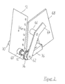
- FIG. 2 shows a view of the sensor unit 30 for scanning the web 12.
- a friction wheel 60 is in frictional contact with the edge of the web 12, so that its rotational speed is directly related to the actual speed V actual of the web 12.
- the friction wheel 60 is characterized by a high coefficient of friction on its surface, which increases the frictional engagement with the web 12. Scanning the web 12 at its edge ensures that the freshly fixed toner image is not affected by the scanning process. If the web 12 is additionally perforated, the perforation increases the frictional engagement of the friction wheel 60 with the web 12.
- the friction wheel 60 is rotatably mounted on an axis 62 which is attached to a first end of a holding element 64.
- the holding element 64 is attached to a spacer 66 is fixed to a frame 68, rotatably mounted.
- a Spring force not shown, at the other end of the holding element 64 is the frictional engagement of the friction wheel 60 with the edge the web 12 increased.
- a guide roller 70 transversely to the conveying direction the web 12 attached in such a way that the guide roller 70th also serves as a counter pressure roller for the friction wheel 60.
- the friction wheel 60 is rotatably connected to a hollow shaft 72.
- the hollow shaft 72 is a gear influencing the magnetic field 74 rotatably connected, so that the friction wheel 60, the hollow shaft 72 and the gear 74 form a unit.
- the unit 60, 72, 74 is rotatably mounted on the axis 62 and has the Function of an encoder, which also includes a sensor module 76 heard.
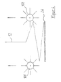
- Figure 3 shows an arrangement of sensors 80 and 82 within the sensor assembly 76.
- the teeth of the gear 74 have an equal tooth spacing to each other a.
- the sensor assembly 76 contains two magnetic sensors 80 and 82 that you electrical behavior, e.g. their current or voltage value, change when turning the teeth of the gear 74.
- magnetic sensors 80 and 82 can e.g. deficiency resistive Sensors are used to measure their resistance under the Change the influence of a changing magnetic field.
- the magnetic field change is achieved by the approximation of a tooth of the Gear 74 causes.
- Both sensors 80 and 82 have Direction of rotation of the gear 74 the sensor distance b.
- the change the voltage values are given via lines 84 and 86 detected in a sensor circuit 88.
- the sensor circuit 88 amplifies the voltage or current changes and gives rectangular impulses Sensor signals 32 and 34 off.
- FIG. 4 shows an arrangement of impellers 100 and 102 to monitor the folding of the web 12.
- the fixing process is the web 12 as already mentioned on the Stack 26 folded together. Folding the web happens along folds, each one sheet of the Limit stack 26 in the direction of transport, under the influence of Weight force of the web 12. Since the impellers 100 and 102 are easily rotatably mounted and with the web 12 in the Figure 4 are engaged, they are through the weight of the folding on the stack 26 Sheets of web 12 set in rotation.
- the impellers 100, 102 are each with an arrangement of hollow shaft 72, gear 74 and sensor assembly 76 combined so that Sensor signals 32, 34 corresponding to the rotary movement of the impellers 100, 102 can be generated.
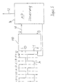
- Figure 5 shows the principle of the circuit 46 for generating a Error signal from the sensor signals 32 and 34.
- the signal state A corresponds to that shown in FIG. 3 Position of the gear 74.
- the tooth 90 causes both Sensors 80 and 82 make a corresponding change in electrical Voltage, which is in a high voltage value of the Sensor signals 32 and 34 expresses.
- the gear 74 turns that indicated in Figure 3 with the aid of an arrow indicating the direction of rotation Direction on its circumference by the value a / 4, so the sensor 80 is no longer influenced by the tooth 90, so that the voltage of the sensor 80 has a rest value. So that's the State B reached in which the sensor signal 32 is low and the sensor signal 34 has a high voltage value.
- the two sensor signals 32 and 34 are fed to a single-edge controlled D flip-flop 80.
- the sensor signal 32 drives the signal input 1D of the D flip-flop 80.
- the sensor signal 34 is fed to the clock input C1. Circuit details, such as the wiring of the input S for setting the D flip-flop 80 in a certain state and the output Q are not shown in FIG. 5 because they are familiar to the person skilled in the art. This also applies to electrical protective measures and a possible electrical improvement of sensor signals 32 and 34, such as an increase in the slope.
- the D flip-flop 80 can be set into a defined initial state by the microprocessor controller 36 via the reset input R.
- the output Q of the D flip-flop 80 is evaluated directly by the microprocessor control, since the error signal 48 is present there.
- the sensor signals 32 and 34 can control the microprocessor can be supplied directly as a speed signal 50.
- the circuit according to Figure 5 by a XOR gate at one input the sensor signal 32 and sensor signal 34 is present at its other input complete. A single one is created at the output of the XOR gate Signal that is the speed information of the sensor signals 32 and 34 combined, since it is twice as high Frequency as one of the sensor signals 32 and 34 has.
- the output signal of the XOR gate is then the microprocessor controller supplied as a speed signal 50.
Landscapes
- Physics & Mathematics (AREA)
- General Physics & Mathematics (AREA)
- Fixing For Electrophotography (AREA)
- Controlling Sheets Or Webs (AREA)
Description
- Fig. 1
- eine schematische Darstellung einer Einrichtung zum Überwachen des Betriebs einer Fixierstation,
- Fig. 2
- eine Ansicht einer Sensoreinheit zum Abtasten der Bahn,
- Fig. 3
- eine Anordnung von Sensoren innerhalb einer Sensorbaugruppe,
- Fig. 4
- eine Anordnung von Flügelrädern zum Überwachen des Zusammenfaltens der Bahn, und
- Fig. 5
- eine elektrische Schaltung zum Erzeugen eines Fehlersignals aus den Sensorsignalen der Sensoreinheit.
Claims (9)
- Einrichtung zum Überwachen des Betriebs einer Fixierstation (10) eines elektrographischen Druckers, der eine Bahn (12) aus Endlos-Trägermaterial mit einem Farbpartikel enthaltenden Tonerbild bedruckt,wobei die Bahn (12) mit vorbestimmter Transportgeschwindigkeit (VSoll) durch die Fixierstation (10) gefördert wird, deren Fixierrollen (16, 18) die Farbpartikel auf der Bahn (12) fixieren,wobei die aus der Fixierstation (10) geförderte Bahn (12) durch eine Sensoreinheit (30) abgetastet wird, die die Ist-Geschwindigkeit (VIst) der Bahn (12) erfaßt,und wobei eine Steuerung (36) die Ist-Geschwindigkeit (VIst) mit der vorbestimmten Transportgeschwindigkeit (VSoll) vergleicht und abhängig vom Vergleich ein Signal (52) über den Betriebszustand der Fixierstation (10) erzeugt,
dadurch gekennzeichnet daß die Seinsoreinheit (30) zusätzlich die Transportrichtung der Bahn erfaßt, die Steuerung (36) diese Transportrichtung mit der vorbestimmten Transportrichtung vergleicht und bei einer Umkehr der Transportrichtung dem Fixierbetrieb unterbricht. - Einrichtung nach Anspruch 1, dadurch gekennzeichnet, daß die Sensoreinheit (30) ein die Bahn (12) abtastendes Rad (60) enthält, das mit einem Drehgeber (74, 76) verbunden ist, der die Ist-Geschwindigkeit (VIst) erfaßt.
- Einrichtung nach Anspruch 2, dadurch gekennzeichnet, daß bei einer faltbaren Bahn (12) das Rad als Flügelrad ausgebildet ist, dessen Flügel durch sich auf einen Stapel (26) faltende Blätter gedreht werden.
- Einrichtung nach Anspruch 2 oder 3, dadurch gekennzeichnet, daß der Drehgeber (74, 76) ein aus magnetischem Material bestehendes Zahnrad (74) enthält, dessen Zähne nacheinander an zwei voneinander beabstandeten magnetischen Sensoren vorbeigeführt werden, deren Ausgangssignale (32, 34) die Ist-Geschwindigkeit (VIst) abbilden.
- Einrichtung nach Anspruch 4, dadurch gekennzeichnet, daß der Abstand der Sensoren kleiner als der halbe Abstand zweier benachbarte Zähne ist.
- Einrichtung nach einem der vorhergehenden Ansprüche, dadurch gekennzeichnet, daß die Steuerung (36) eine eingangsseitig mit der Sensoreinheit (30) verbundene elektrische Schaltung (46) zum Erzeugen eines Fehlersignals (48) bei Umkehr der Förderrichtung enthält.
- Einrichtung nach Anspruch 6, dadurch gekennzeichnet, daß die elektrische Schaltung (46) das Fehlersignal (48) an einem Ausgang (Q) eines D-Flipflops (80) erzeugt, dessen Takteingang (1) von einem der Ausgangssignale (32 bzw. 34) und dessen Signaleingang (15) vom anderen Ausgangssignal (34 bzw. 32) angesteuert wird.
- Einrichtung nach einem der vorhergehenden Ansprüche, dadurch gekennzeichnet, daß die Steuerung (36) bei Abweichung der Ist-Geschwindigkeit (VIst) von der vorbestimmten Transportgeschwindigkeit (VSoll) um ein vorgegebenes Maß den Betrieb der Fixierstation (10) bzw. des Druckers anhält.
- Einrichtung nach Anspruch 8, dadurch gekennzeichnet, daß durch die Steuerung (36) die Ist-Geschwindigkeit (VIst) innerhalb eines vorbestimmten Zeitfensters gemittelt wird und die gemittelte Ist-Geschwindigkeit zum Vergleich mit der Transportgeschwindigkeit (VSoll) herangezogen wird.
Applications Claiming Priority (3)
| Application Number | Priority Date | Filing Date | Title |
|---|---|---|---|
| DE19539697 | 1995-10-25 | ||
| DE19539697 | 1995-10-25 | ||
| PCT/DE1996/001281 WO1997015870A1 (de) | 1995-10-25 | 1996-07-15 | Einrichtung zum überwachen des betriebs einer fixierstation eines elektrographischen druckers |
Publications (2)
| Publication Number | Publication Date |
|---|---|
| EP0871929A1 EP0871929A1 (de) | 1998-10-21 |
| EP0871929B1 true EP0871929B1 (de) | 2001-10-24 |
Family
ID=7775722
Family Applications (1)
| Application Number | Title | Priority Date | Filing Date |
|---|---|---|---|
| EP96924738A Expired - Lifetime EP0871929B1 (de) | 1995-10-25 | 1996-07-15 | Einrichtung zum überwachen des betriebs einer fixierstation eines elektrographischen druckers |
Country Status (4)
| Country | Link |
|---|---|
| US (1) | US5978613A (de) |
| EP (1) | EP0871929B1 (de) |
| DE (1) | DE59608029D1 (de) |
| WO (1) | WO1997015870A1 (de) |
Families Citing this family (3)
| Publication number | Priority date | Publication date | Assignee | Title |
|---|---|---|---|---|
| US7733017B2 (en) | 2005-07-08 | 2010-06-08 | Peysakh Shapiro | Display apparatus with replaceable electroluminescent element |
| US9116478B2 (en) * | 2012-04-19 | 2015-08-25 | Xerox Corporation | Method and apparatus for avoiding fuser jams in an image production device |
| JP7073704B2 (ja) * | 2017-12-13 | 2022-05-24 | コニカミノルタ株式会社 | 画像形成装置、画像形成システム、画像形成装置の制御方法及びプログラム |
Family Cites Families (6)
| Publication number | Priority date | Publication date | Assignee | Title |
|---|---|---|---|---|
| JPS5521334A (en) * | 1978-07-28 | 1980-02-15 | Toshiba Corp | Feed monitoring unit for paper feeding system |
| JPS6285268A (ja) * | 1985-10-11 | 1987-04-18 | Fuji Xerox Co Ltd | カラ−複写機 |
| JPH0242471A (ja) * | 1988-08-01 | 1990-02-13 | Nec Corp | 電子写真装置の定着装置 |
| US5043763A (en) * | 1988-09-19 | 1991-08-27 | Canon Kabushiki Kaisha | Image forming apparatus having a heater in contact with a film to fix a toner image |
| US5063845A (en) * | 1990-02-16 | 1991-11-12 | Perretta Graphics Corporation | Anti-wrap for high speed printing press |
| US5313253A (en) * | 1992-08-17 | 1994-05-17 | Xerox Corporation | Paper path signature analysis apparatus |
-
1996
- 1996-07-15 US US09/065,070 patent/US5978613A/en not_active Expired - Lifetime
- 1996-07-15 WO PCT/DE1996/001281 patent/WO1997015870A1/de not_active Ceased
- 1996-07-15 DE DE59608029T patent/DE59608029D1/de not_active Expired - Lifetime
- 1996-07-15 EP EP96924738A patent/EP0871929B1/de not_active Expired - Lifetime
Also Published As
| Publication number | Publication date |
|---|---|
| US5978613A (en) | 1999-11-02 |
| WO1997015870A1 (de) | 1997-05-01 |
| DE59608029D1 (de) | 2001-11-29 |
| EP0871929A1 (de) | 1998-10-21 |
Similar Documents
| Publication | Publication Date | Title |
|---|---|---|
| DE69721591T2 (de) | Rolle von Bandmaterial zur Verwendung in einer Vorrichtung zum Verpacken von Medikamenten | |
| DE69319132T2 (de) | Thermodrucker | |
| DE69902418T2 (de) | Reibungsantriebsgerät für Streifenmaterial | |
| DE69004483T2 (de) | Steuerung für einen Labeldrucker. | |
| DE60313725T2 (de) | Laden mit Schrittmotor | |
| DE2660304C2 (de) | Vorrichtung zur Einhaltung des Passers beim Druck mit einer Mehrfarben-Rollen-Rotationsdruckmaschine | |
| DE3803765A1 (de) | Verfahren und vorrichtung zum steuern der spannung eines bandes | |
| DE3406310A1 (de) | Etikettiermaschine | |
| DE2414811C2 (de) | Farbbandantrieb für einen Drucker | |
| DE69915163T2 (de) | Halter für Rollendruckmedien, Rollendruckmedienkassette und Druckvorrichtung | |
| DE102008048659A1 (de) | Vorrichtung und Verfahren zum Ausrichten von Bögen | |
| DE102009003237A1 (de) | Verfahren zur Korrektur einer Schräglage eines Produktes auf einem Falztisch eines Längsfalzapparates und ein Längsfalzapparat | |
| DE3817130A1 (de) | Drucker fuer kontinuierliche aufzeichnungstraeger | |
| WO2017076533A1 (de) | Vorrichtung und verfahren zum bedrucken von etiketten mittels thermodruck | |
| DE69031254T2 (de) | Etikettenlösevorrichtung in einem Etikettendrucker | |
| DE69700482T2 (de) | Maschine und Verfahren zum vorbestimmten Bearbeiten von Blattmaterial mit einer Länge verbrauchbaren Bandes | |
| DE3034212C2 (de) | Rotationsdruckmaschine mit einer Bogenstapelmarkierungsvorrichtung | |
| DE68907892T2 (de) | Überwachungsvorrichtung für den farbbandtransport. | |
| DE3716233C2 (de) | ||
| DE3344595C2 (de) | Vorrichtung zum Heben und Transportieren von Farb- und Korrekturbändern in elektronisch gesteuerten Schreib- und ähnlichen Maschinen | |
| DE2233879B2 (de) | Einrichtung zum Einstellen der Schwingungsamplitude Zickzack-Falzapparaten | |
| DE4306814C2 (de) | Anordnung zum Bedrucken und anschließenden Falten und Stapeln eines Endlosformulars | |
| EP0871929A1 (de) | Einrichtung zum überwachen des betriebs einer fixierstation eines elektrographischen druckers | |
| EP0861797A1 (de) | Wechselvorrichtung einer Verpackungsmaschine für eine Vorratsrolle einer Folienbahn | |
| WO1996030812A1 (de) | Einrichtung zum positionsgenauen synchronisieren des parallellaufs von aufzeichnungsträgerbahnen in einer elektrografischen druckeinrichtung |
Legal Events
| Date | Code | Title | Description |
|---|---|---|---|
| PUAI | Public reference made under article 153(3) epc to a published international application that has entered the european phase |
Free format text: ORIGINAL CODE: 0009012 |
|
| 17P | Request for examination filed |
Effective date: 19980520 |
|
| AK | Designated contracting states |
Kind code of ref document: A1 Designated state(s): DE FR GB |
|
| GRAG | Despatch of communication of intention to grant |
Free format text: ORIGINAL CODE: EPIDOS AGRA |
|
| 17Q | First examination report despatched |
Effective date: 20001130 |
|
| GRAG | Despatch of communication of intention to grant |
Free format text: ORIGINAL CODE: EPIDOS AGRA |
|
| GRAH | Despatch of communication of intention to grant a patent |
Free format text: ORIGINAL CODE: EPIDOS IGRA |
|
| GRAH | Despatch of communication of intention to grant a patent |
Free format text: ORIGINAL CODE: EPIDOS IGRA |
|
| GRAA | (expected) grant |
Free format text: ORIGINAL CODE: 0009210 |
|
| AK | Designated contracting states |
Kind code of ref document: B1 Designated state(s): DE FR GB |
|
| PG25 | Lapsed in a contracting state [announced via postgrant information from national office to epo] |
Ref country code: GB Free format text: LAPSE BECAUSE OF FAILURE TO SUBMIT A TRANSLATION OF THE DESCRIPTION OR TO PAY THE FEE WITHIN THE PRESCRIBED TIME-LIMIT Effective date: 20011024 Ref country code: FR Free format text: LAPSE BECAUSE OF FAILURE TO SUBMIT A TRANSLATION OF THE DESCRIPTION OR TO PAY THE FEE WITHIN THE PRESCRIBED TIME-LIMIT Effective date: 20011024 |
|
| REF | Corresponds to: |
Ref document number: 59608029 Country of ref document: DE Date of ref document: 20011129 |
|
| GBV | Gb: ep patent (uk) treated as always having been void in accordance with gb section 77(7)/1977 [no translation filed] |
Effective date: 20011024 |
|
| EN | Fr: translation not filed | ||
| PLBE | No opposition filed within time limit |
Free format text: ORIGINAL CODE: 0009261 |
|
| STAA | Information on the status of an ep patent application or granted ep patent |
Free format text: STATUS: NO OPPOSITION FILED WITHIN TIME LIMIT |
|
| 26N | No opposition filed | ||
| PGFP | Annual fee paid to national office [announced via postgrant information from national office to epo] |
Ref country code: DE Payment date: 20120928 Year of fee payment: 17 |
|
| PG25 | Lapsed in a contracting state [announced via postgrant information from national office to epo] |
Ref country code: DE Free format text: LAPSE BECAUSE OF NON-PAYMENT OF DUE FEES Effective date: 20140201 |
|
| REG | Reference to a national code |
Ref country code: DE Ref legal event code: R119 Ref document number: 59608029 Country of ref document: DE Effective date: 20140201 |