EP0871247B1 - Reihenklemme mit Sammelschienenanschluss - Google Patents
Reihenklemme mit Sammelschienenanschluss Download PDFInfo
- Publication number
- EP0871247B1 EP0871247B1 EP98104359A EP98104359A EP0871247B1 EP 0871247 B1 EP0871247 B1 EP 0871247B1 EP 98104359 A EP98104359 A EP 98104359A EP 98104359 A EP98104359 A EP 98104359A EP 0871247 B1 EP0871247 B1 EP 0871247B1
- Authority
- EP
- European Patent Office
- Prior art keywords
- terminal strip
- insulating material
- strip according
- bend
- slide
- Prior art date
- Legal status (The legal status is an assumption and is not a legal conclusion. Google has not performed a legal analysis and makes no representation as to the accuracy of the status listed.)
- Expired - Lifetime
Links
- 239000011810 insulating material Substances 0.000 claims description 16
- 239000004020 conductor Substances 0.000 claims description 15
- 230000000087 stabilizing effect Effects 0.000 claims description 2
- 230000007935 neutral effect Effects 0.000 description 5
- 238000006073 displacement reaction Methods 0.000 description 2
- 238000004519 manufacturing process Methods 0.000 description 2
- 239000000463 material Substances 0.000 description 2
- 238000005452 bending Methods 0.000 description 1
- 230000006835 compression Effects 0.000 description 1
- 238000007906 compression Methods 0.000 description 1
- 230000001419 dependent effect Effects 0.000 description 1
- 238000000034 method Methods 0.000 description 1
Images

Classifications
-
- H—ELECTRICITY
- H01—ELECTRIC ELEMENTS
- H01R—ELECTRICALLY-CONDUCTIVE CONNECTIONS; STRUCTURAL ASSOCIATIONS OF A PLURALITY OF MUTUALLY-INSULATED ELECTRICAL CONNECTING ELEMENTS; COUPLING DEVICES; CURRENT COLLECTORS
- H01R9/00—Structural associations of a plurality of mutually-insulated electrical connecting elements, e.g. terminal strips or terminal blocks; Terminals or binding posts mounted upon a base or in a case; Bases therefor
- H01R9/22—Bases, e.g. strip, block, panel
- H01R9/24—Terminal blocks
- H01R9/26—Clip-on terminal blocks for side-by-side rail- or strip-mounting
- H01R9/2675—Electrical interconnections between two blocks, e.g. by means of busbars
-
- H—ELECTRICITY
- H01—ELECTRIC ELEMENTS
- H01R—ELECTRICALLY-CONDUCTIVE CONNECTIONS; STRUCTURAL ASSOCIATIONS OF A PLURALITY OF MUTUALLY-INSULATED ELECTRICAL CONNECTING ELEMENTS; COUPLING DEVICES; CURRENT COLLECTORS
- H01R4/00—Electrically-conductive connections between two or more conductive members in direct contact, i.e. touching one another; Means for effecting or maintaining such contact; Electrically-conductive connections having two or more spaced connecting locations for conductors and using contact members penetrating insulation
- H01R4/28—Clamped connections, spring connections
- H01R4/48—Clamped connections, spring connections utilising a spring, clip, or other resilient member
- H01R4/4809—Clamped connections, spring connections utilising a spring, clip, or other resilient member using a leaf spring to bias the conductor toward the busbar
- H01R4/48185—Clamped connections, spring connections utilising a spring, clip, or other resilient member using a leaf spring to bias the conductor toward the busbar adapted for axial insertion of a wire end
- H01R4/4819—Clamped connections, spring connections utilising a spring, clip, or other resilient member using a leaf spring to bias the conductor toward the busbar adapted for axial insertion of a wire end the spring shape allowing insertion of the conductor end when the spring is unbiased
- H01R4/4821—Single-blade spring
-
- H—ELECTRICITY
- H01—ELECTRIC ELEMENTS
- H01R—ELECTRICALLY-CONDUCTIVE CONNECTIONS; STRUCTURAL ASSOCIATIONS OF A PLURALITY OF MUTUALLY-INSULATED ELECTRICAL CONNECTING ELEMENTS; COUPLING DEVICES; CURRENT COLLECTORS
- H01R4/00—Electrically-conductive connections between two or more conductive members in direct contact, i.e. touching one another; Means for effecting or maintaining such contact; Electrically-conductive connections having two or more spaced connecting locations for conductors and using contact members penetrating insulation
- H01R4/28—Clamped connections, spring connections
- H01R4/48—Clamped connections, spring connections utilising a spring, clip, or other resilient member
- H01R4/4809—Clamped connections, spring connections utilising a spring, clip, or other resilient member using a leaf spring to bias the conductor toward the busbar
- H01R4/4811—Spring details
- H01R4/4816—Spring details the spring shape preventing insertion of the conductor end when the spring is unbiased
-
- H—ELECTRICITY
- H01—ELECTRIC ELEMENTS
- H01R—ELECTRICALLY-CONDUCTIVE CONNECTIONS; STRUCTURAL ASSOCIATIONS OF A PLURALITY OF MUTUALLY-INSULATED ELECTRICAL CONNECTING ELEMENTS; COUPLING DEVICES; CURRENT COLLECTORS
- H01R4/00—Electrically-conductive connections between two or more conductive members in direct contact, i.e. touching one another; Means for effecting or maintaining such contact; Electrically-conductive connections having two or more spaced connecting locations for conductors and using contact members penetrating insulation
- H01R4/28—Clamped connections, spring connections
- H01R4/48—Clamped connections, spring connections utilising a spring, clip, or other resilient member
- H01R4/4809—Clamped connections, spring connections utilising a spring, clip, or other resilient member using a leaf spring to bias the conductor toward the busbar
- H01R4/4846—Busbar details
- H01R4/485—Single busbar common to multiple springs
Definitions
- the contact part as essentially S-shaped spring is formed, one S-bow of the busbar and the other S-arm in the corresponding end position, the busbar embraces.
- Such a contact part can be made of tape material very easily by simple bending processes.
- the contact part is in one piece because the S configuration offers two contact springs in one. With appropriate The configuration of the spring width and the spring force is provided by the S-shaped spring it is no longer necessary to arrange and assemble two contact elements, very good management and contacting properties.
Landscapes
- Connections Arranged To Contact A Plurality Of Conductors (AREA)
- Coupling Device And Connection With Printed Circuit (AREA)
- Connector Housings Or Holding Contact Members (AREA)
Description
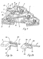
- Figur 1
- eine mehretagige Reihenklemme mit Sammelschienenanschluß, einer Stromschiene mit Nulleiteranschluß und einen Trennschieber;
- Fig. 2a + 2b
- vereinfachte Einzelansichten der das Kontaktteil des Trennschiebers bildenden S-förmigen Feder sowie der Stromschiene und der Sammelschiene in den beiden Endstellungen des Trennschiebers;
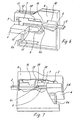
- Figur 3
- eine Teilschnittdarstellung durch einen Trennschieber, montiert in einer Aufnahmezone im Klemmengehäuse;
- Fig. 4 + 5
- Draufsichten auf die Anordnung nach Figur 3 mit Illustration der Erstmontage des Trennschiebers;
- Figur 6
- eine weitere Ausführungsform eines Trennschiebers;
- Figur 7
- eine teilweise aufgebrochene Rückansicht der Anordnung nach Figur 6.
Claims (14)
- Reihenklemme mit Sammelschienenanschluß, mit einem in dem Isolierstoffgehäuse (1) verschieblich geführten Trennschieber (5), der ein Kontaktteil (6) aufweist, das in einer ersten Endstellung des Trennschiebers eine einen Leiteranschluß (3) aufweisende Stromschiene (2) der Reihenklemme und in einer zweiten Endstellung die Stromschiene (2) sowie eine quer in Anreihrichtung der Reihenklemmen vorbeigeführte Sammelschiene (4) kontaktiert, dadurch gekennzeichnet, daß das Kontaktteil (6) als im wesentlichen S-förmige Feder ausgebildet ist, deren einer S-Bogen (6a) die Stromschiene (2) und deren anderer S-Bogen (6c) in der entsprechenden Endstellung die Sammelschiene (4) kontaktierend umgreift.
- Reihenklemme nach Anspruch 1, dadurch gekennzeichnet, daß der die Stromschiene (2) umgreifende obere S-Bogen (6a) der S-förmigen Feder an seinem freien Ende einen die Stromschiene (2) kontaktierenden Verlängerungsabschnitt (6b) aufweist.
- Reihenklemme nach Anspruch 1 oder 2, dadurch gekennzeichnet, daß der untere, die Sammelschiene (4) umgreifende S-Bogen (6c) der S-förmigen Feder nach unten mittels eines Bogenabschnittes (6d) um ein Stützbein (6e) verlängert ist, für dessen freies unteres Ende im umgebenden Isolierstoffbereich eine Anschlagfläche (11) gebildet ist.
- Reihenklemme nach einem der vorhergehenden Ansprüche, dadurch gekennzeichnet, daß der Abstand (L1) zwischen dem Krümmungsmittelpunkt des oberen S-Bogens (6a) und dem Krümmungsmittelpunkt des unteren S-Bogens (6c) kleiner ist als der Abstand (L2) zwischen dem Krümmungsmittelpunkt des unteren S-Bogens (6c) und dem Krümmungsmittelpunkt des Bogenabschnittes (6d).
- Reihenklemme nach einem der vorhergehenden Ansprüche, dadurch gekennzeichnet, daß der Trennschieber (5) ein Isolierstoffteil (7) aufweist, in dem unterseitig der obere Bereich des oberen S-Bogens (6a) des Kontaktteiles (6) in Form der S-förmigen Feder angeordnet und abgestützt ist.
- Reihenklemme nach Anspruch 5, dadurch gekennzeichnet, daß der Trennschieber (5) mittels des Isolierstoffteiles (7) in einer Aufnahmezone (8) des Isolierstoffgehäuses (1) der Reihenklemme verschieblich geführt und gehalten ist.
- Reihenklemme nach Anspruch 6, dadurch gekennzeichnet, daß in der Aufnahmezone (8) oberseitig über dem Isolierstoffteil (7) des Trennschiebers (5) eine nach oben offene schlitzförmige Führung (12) gebildet ist und oberseitig auf dem Isolierstoffteil (7) ein Zapfen (13) vorgesehen ist, der in der Führung (12) geführt ist und der in dieser von oben sichtbar emporsteht.
- Reihenklemme nach einem der Ansprüche 5 bis 7, dadurch gekennzeichnet, daß das Isolierstoffteil (7) des Trennschiebers (5) oberseitig einen Betätigungsschlitz (18) aufeist, für den in der Aufnahmezone (8) ein nach oben offener Zugangsraum vorgesehen ist.
- Reihenklemme nach Anspruch 6, dadurch gekennzeichnet, daß in der Aufnahmezone (8) eine rückwandig und oberseitig begrenzte Führung (10) für das Isolierstoffteil (7) des Trennschiebers (5) gebildet ist.
- Reihenklemme nach Anspruch 9, dadurch gekennzeichnet, daß gegenüberliegend der Rückwand der Führung (10) an der freien Kante der oberseitigen Führung nach unten vorspringend eine Haltelasche (14) vorgesehen ist, die in jeder Betriebsstellung des Trennschiebers (5) einen Teilbereich seines Isolierstoffteiles (7) überdeckt.
- Reihenklemme nach Anspruch 10, dadurch gekennzeichnet, daß der Trennschieber (5) mit dem Kontaktteil (6) und dem Isolierstoffteil (7) in einer Extremendstellung in die Führung (10) des Aufnahme- und Führungsteiles (8), an der Haltelasche (14) vorbei, einschwenkbar ist und das Wiedererreichen dieser Extremendstellung im Normalbetrieb durch zwischen der Stromschiene (2) und dem Trennschieber (5) wirkende Anschläge (15, 17; 20, 21) blockiert ist.
- Reihenklemme nach Anspruch 11, dadurch gekennzeichnet, daß an der S-förmigen Feder an der Unterseite des Verlängerungsabschnittes (6b) ein Anschlagstück (15) vorgesehen ist, für das am Ende einer Aufnahme (16) in der Stromschiene (2) an deren freien Ende eine Schulter (17) gebildet ist derart, daß hierdurch die betriebliche Endstellung des Trennschiebers (5) zur Kontaktierung der Sammelschiene (4) in Richtung auf die weiter außen liegende Extremendstellung für die Montage begrenzt ist.
- Reihenklemme nach Anspruch 10, dadurch gekennzeichnet, daß an der Stromschiene (2) mittels einer seitlichen Ausklinkung an ihrem freien Ende ein Anschlag (20) gebildet ist und an dem Isolierstoffteil (7) des Trennschiebers (5) ein nach unten neben die Stromschiene (2) vorspringender weiterer Anschlag (21) gebildet ist derart, daß die Anschläge (20, 21) die betriebliche Endstellung des Endschiebers (5) zur Kontaktierung der Sammelschiene (4) in Richtung auf die weiter außen liegende Extremendstellung für die Montage begrenzen.
- Reihenklemme nach einem der vorhergehenden Ansprüche, dadurch gekennzeichnet, daß in der Aufnahmezone (8) ein zusätzliches Stabilisierungs- und Führungsstück (19) vorgesehen ist, das mit dem unteren S-Bogen (6c) der S-förmigen Feder zusammenwirkt.
Applications Claiming Priority (2)
| Application Number | Priority Date | Filing Date | Title |
|---|---|---|---|
| DE19714633 | 1997-04-09 | ||
| DE19714633A DE19714633C1 (de) | 1997-04-09 | 1997-04-09 | Reihenklemme mit Sammelschienenanschluß |
Publications (3)
| Publication Number | Publication Date |
|---|---|
| EP0871247A2 EP0871247A2 (de) | 1998-10-14 |
| EP0871247A3 EP0871247A3 (de) | 1999-08-25 |
| EP0871247B1 true EP0871247B1 (de) | 2003-12-17 |
Family
ID=7825897
Family Applications (1)
| Application Number | Title | Priority Date | Filing Date |
|---|---|---|---|
| EP98104359A Expired - Lifetime EP0871247B1 (de) | 1997-04-09 | 1998-03-11 | Reihenklemme mit Sammelschienenanschluss |
Country Status (4)
| Country | Link |
|---|---|
| EP (1) | EP0871247B1 (de) |
| AT (1) | ATE256923T1 (de) |
| DE (2) | DE19714633C1 (de) |
| ES (1) | ES2210607T3 (de) |
Families Citing this family (13)
| Publication number | Priority date | Publication date | Assignee | Title |
|---|---|---|---|---|
| DE10049696A1 (de) * | 2000-10-07 | 2002-04-25 | Wieland Electric Gmbh | Sammelschienenhalter |
| DE10158948A1 (de) * | 2001-12-03 | 2003-06-12 | Wago Verwaltungs Gmbh | Sammelanschluss für elektr. Verteileranlagen |
| DE20120811U1 (de) * | 2001-12-21 | 2003-04-30 | Weidmüller Interface GmbH & Co., 32760 Detmold | Sammelschienen-Anschlußklemme |
| DE102004018904B4 (de) * | 2004-04-15 | 2013-11-14 | Wago Verwaltungsgesellschaft Mbh | Schraubenloser Sammelschienenanschluss für elektrische Klemmen |
| DE102004037083B4 (de) * | 2004-04-27 | 2016-07-28 | Dehn + Söhne Gmbh + Co. Kg | Überspannungsableiter-Anordnung mit einer als Bestandteil eines Gehäuses ausführbaren Trägerplatte |
| DE102005008899B4 (de) * | 2005-02-01 | 2007-04-19 | Wieland Electric Gmbh | Neutralleiter-Trennklemme |
| DE102008014180B4 (de) | 2008-03-14 | 2011-07-14 | Phoenix Contact GmbH & Co. KG, 32825 | Trennklemme, insbesondere Neutralleiter-Trennklemme |
| DE102011001152B4 (de) | 2011-03-08 | 2012-12-20 | Phoenix Contact Gmbh & Co. Kg | Kontaktelement und Kontaktelementbaueinheit |
| DE202013104784U1 (de) * | 2012-10-30 | 2014-01-31 | Weidmüller Interface GmbH & Co. KG | Reihenbausteinanordnung mit einem Energiebussystem |
| DE102014116811A1 (de) * | 2014-11-18 | 2016-05-19 | Phoenix Contact Gmbh & Co. Kg | Reihenklemme |
| DE102015110874A1 (de) * | 2015-07-06 | 2017-01-12 | Phoenix Contact Gmbh & Co. Kg | Anschlussklemme |
| DE102015110868A1 (de) * | 2015-07-06 | 2017-01-12 | Phoenix Contact Gmbh & Co. Kg | Anschlussklemme |
| DE102018114811A1 (de) * | 2018-06-20 | 2019-12-24 | Wago Verwaltungsgesellschaft Mbh | Trennklemme zur manuell trennbaren elektrischen Kontaktierung eines elektrischen Leiters mit einer Sammelstromschiene sowie Klemmenblock und Verteilerschrank mit mehreren Trennklemmen |
Family Cites Families (5)
| Publication number | Priority date | Publication date | Assignee | Title |
|---|---|---|---|---|
| DE7802224U1 (de) * | 1978-01-26 | 1978-06-22 | C. A. Weidmueller Kg, 4930 Detmold | Dreifachreihenklemme |
| DE4034204C2 (de) * | 1990-10-27 | 2002-04-18 | Wago Verwaltungs Gmbh | Elektrische Klemme mit Sammelschienenanschluß |
| DE9315474U1 (de) * | 1993-10-09 | 1994-01-13 | Wago Verwaltungsgesellschaft Mbh, 32423 Minden | Elektrische Klemme mit einem Sammelschienenanschluß |
| DE59604393D1 (de) * | 1995-05-18 | 2000-03-16 | Wieland Electric Gmbh | Sammelschienen-Anschlussklemme |
| DE29605365U1 (de) * | 1996-03-22 | 1996-05-30 | Conrad, Gerd, 33104 Paderborn | Trennklemme, insbesondere für Nulleiter |
-
1997
- 1997-04-09 DE DE19714633A patent/DE19714633C1/de not_active Expired - Fee Related
-
1998
- 1998-03-11 EP EP98104359A patent/EP0871247B1/de not_active Expired - Lifetime
- 1998-03-11 DE DE59810432T patent/DE59810432D1/de not_active Expired - Lifetime
- 1998-03-11 AT AT98104359T patent/ATE256923T1/de active
- 1998-03-11 ES ES98104359T patent/ES2210607T3/es not_active Expired - Lifetime
Also Published As
| Publication number | Publication date |
|---|---|
| EP0871247A2 (de) | 1998-10-14 |
| DE59810432D1 (de) | 2004-01-29 |
| ES2210607T3 (es) | 2004-07-01 |
| DE19714633C1 (de) | 1998-07-16 |
| ATE256923T1 (de) | 2004-01-15 |
| EP0871247A3 (de) | 1999-08-25 |
Similar Documents
| Publication | Publication Date | Title |
|---|---|---|
| EP1109269B1 (de) | Elektrischer Anschlusskontakt und Lampenfassung mit einem solchen Kontakt | |
| DE2907232C2 (de) | Selbsttätig sperrender Reißverschlußschieber | |
| DE69604331T2 (de) | Verbindermodul mit Zugang zu Test- und Anschlusszwecken | |
| DE112019001295B4 (de) | Anschlussklemme | |
| EP4150714B1 (de) | Anschlusseinheit, anschlussanordnung und elektronisches gerät | |
| WO2017220490A1 (de) | Leiteranschlussklemme | |
| DE19714633C1 (de) | Reihenklemme mit Sammelschienenanschluß | |
| DE4338762A1 (de) | Druckknopfschalter | |
| EP0606241A1 (de) | Steckverbinder mit kurzschlussbrücke. | |
| DE69500017T2 (de) | Verbinder für integrierte Schaltungspackung | |
| DE60027079T2 (de) | Druckkontakt-Verbinder | |
| DE102009030645A1 (de) | Brückerelement und Set aus Klemmelement und Brückerelement | |
| DE1765978B1 (de) | Schaltungsblock zum elektrischen verbinden mittels steck verbindungen von elektrischen schaltungselementen | |
| DE2449950A1 (de) | Schaltereinheit | |
| DE3149310A1 (de) | Vorrichtung und verfahren zur befestigung von elektrischen installationsgeraeten auf normprofilschienen, insbesondere auf hutprofilschienen | |
| DE1195849B (de) | Elektrischer Schnappschalter | |
| WO1997001182A1 (de) | Relais für hohe schaltleistungen | |
| DE102009021460A1 (de) | Stromschienen- und Verbindersystem | |
| CH629917A5 (de) | Schraubenlose klemme fuer elektrische leiter. | |
| DE19704311A1 (de) | Kontaktfeder | |
| EP0806812A2 (de) | Zugfederanschluss für elektrische Leiter mit Anschlagrippen | |
| DE3202579C2 (de) | ||
| EP0833407A2 (de) | Reihenklemme mit Stromschiene | |
| DE102016111626B4 (de) | Leiteranschlussklemme | |
| DE3433000C2 (de) |
Legal Events
| Date | Code | Title | Description |
|---|---|---|---|
| PUAI | Public reference made under article 153(3) epc to a published international application that has entered the european phase |
Free format text: ORIGINAL CODE: 0009012 |
|
| 17P | Request for examination filed |
Effective date: 19980311 |
|
| AK | Designated contracting states |
Kind code of ref document: A2 Designated state(s): AT CH DE ES FR GB IT LI NL |
|
| AX | Request for extension of the european patent |
Free format text: AL;LT;LV;MK;RO;SI |
|
| PUAL | Search report despatched |
Free format text: ORIGINAL CODE: 0009013 |
|
| AK | Designated contracting states |
Kind code of ref document: A3 Designated state(s): AT BE CH DE DK ES FI FR GB GR IE IT LI LU MC NL PT SE |
|
| AX | Request for extension of the european patent |
Free format text: AL;LT;LV;MK;RO;SI |
|
| RIC1 | Information provided on ipc code assigned before grant |
Free format text: 6H 01R 9/24 A, 6H 01R 9/26 B |
|
| AKX | Designation fees paid |
Free format text: AT CH DE ES FR GB IT LI NL |
|
| GRAP | Despatch of communication of intention to grant a patent |
Free format text: ORIGINAL CODE: EPIDOSNIGR1 |
|
| GRAS | Grant fee paid |
Free format text: ORIGINAL CODE: EPIDOSNIGR3 |
|
| GRAA | (expected) grant |
Free format text: ORIGINAL CODE: 0009210 |
|
| AK | Designated contracting states |
Kind code of ref document: B1 Designated state(s): AT CH DE ES FR GB IT LI NL |
|
| REG | Reference to a national code |
Ref country code: GB Ref legal event code: FG4D Free format text: NOT ENGLISH |
|
| REG | Reference to a national code |
Ref country code: CH Ref legal event code: NV Representative=s name: ING. MARCO ZARDI C/O M. ZARDI & CO. S.A. Ref country code: CH Ref legal event code: EP |
|
| REF | Corresponds to: |
Ref document number: 59810432 Country of ref document: DE Date of ref document: 20040129 Kind code of ref document: P |
|
| GBT | Gb: translation of ep patent filed (gb section 77(6)(a)/1977) |
Effective date: 20040121 |
|
| REG | Reference to a national code |
Ref country code: ES Ref legal event code: FG2A Ref document number: 2210607 Country of ref document: ES Kind code of ref document: T3 |
|
| ET | Fr: translation filed | ||
| PLBE | No opposition filed within time limit |
Free format text: ORIGINAL CODE: 0009261 |
|
| STAA | Information on the status of an ep patent application or granted ep patent |
Free format text: STATUS: NO OPPOSITION FILED WITHIN TIME LIMIT |
|
| 26N | No opposition filed |
Effective date: 20040920 |
|
| REG | Reference to a national code |
Ref country code: CH Ref legal event code: PCAR Free format text: ISLER & PEDRAZZINI AG;POSTFACH 1772;8027 ZUERICH (CH) |
|
| PGFP | Annual fee paid to national office [announced via postgrant information from national office to epo] |
Ref country code: NL Payment date: 20120327 Year of fee payment: 15 |
|
| REG | Reference to a national code |
Ref country code: NL Ref legal event code: V1 Effective date: 20131001 |
|
| PG25 | Lapsed in a contracting state [announced via postgrant information from national office to epo] |
Ref country code: NL Free format text: LAPSE BECAUSE OF NON-PAYMENT OF DUE FEES Effective date: 20131001 |
|
| PGFP | Annual fee paid to national office [announced via postgrant information from national office to epo] |
Ref country code: AT Payment date: 20140312 Year of fee payment: 17 |
|
| REG | Reference to a national code |
Ref country code: AT Ref legal event code: MM01 Ref document number: 256923 Country of ref document: AT Kind code of ref document: T Effective date: 20150311 |
|
| PG25 | Lapsed in a contracting state [announced via postgrant information from national office to epo] |
Ref country code: AT Free format text: LAPSE BECAUSE OF NON-PAYMENT OF DUE FEES Effective date: 20150311 |
|
| REG | Reference to a national code |
Ref country code: FR Ref legal event code: PLFP Year of fee payment: 19 |
|
| REG | Reference to a national code |
Ref country code: FR Ref legal event code: PLFP Year of fee payment: 20 |
|
| PGFP | Annual fee paid to national office [announced via postgrant information from national office to epo] |
Ref country code: FR Payment date: 20170322 Year of fee payment: 20 Ref country code: DE Payment date: 20170322 Year of fee payment: 20 Ref country code: CH Payment date: 20170322 Year of fee payment: 20 |
|
| PGFP | Annual fee paid to national office [announced via postgrant information from national office to epo] |
Ref country code: GB Payment date: 20170322 Year of fee payment: 20 |
|
| PGFP | Annual fee paid to national office [announced via postgrant information from national office to epo] |
Ref country code: ES Payment date: 20170315 Year of fee payment: 20 |
|
| PGFP | Annual fee paid to national office [announced via postgrant information from national office to epo] |
Ref country code: IT Payment date: 20170323 Year of fee payment: 20 |
|
| REG | Reference to a national code |
Ref country code: DE Ref legal event code: R071 Ref document number: 59810432 Country of ref document: DE |
|
| REG | Reference to a national code |
Ref country code: CH Ref legal event code: PL |
|
| REG | Reference to a national code |
Ref country code: GB Ref legal event code: PE20 Expiry date: 20180310 |
|
| PG25 | Lapsed in a contracting state [announced via postgrant information from national office to epo] |
Ref country code: GB Free format text: LAPSE BECAUSE OF EXPIRATION OF PROTECTION Effective date: 20180310 |
|
| REG | Reference to a national code |
Ref country code: ES Ref legal event code: FD2A Effective date: 20200721 |
|
| PG25 | Lapsed in a contracting state [announced via postgrant information from national office to epo] |
Ref country code: ES Free format text: LAPSE BECAUSE OF EXPIRATION OF PROTECTION Effective date: 20180312 |