EP0870629A2 - Fahrzeug-Komplettrad - Google Patents
Fahrzeug-Komplettrad Download PDFInfo
- Publication number
- EP0870629A2 EP0870629A2 EP98105697A EP98105697A EP0870629A2 EP 0870629 A2 EP0870629 A2 EP 0870629A2 EP 98105697 A EP98105697 A EP 98105697A EP 98105697 A EP98105697 A EP 98105697A EP 0870629 A2 EP0870629 A2 EP 0870629A2
- Authority
- EP
- European Patent Office
- Prior art keywords
- bead
- rim
- tire
- cavity
- tubular
- Prior art date
- Legal status (The legal status is an assumption and is not a legal conclusion. Google has not performed a legal analysis and makes no representation as to the accuracy of the status listed.)
- Granted
Links
- 239000011324 bead Substances 0.000 claims abstract description 63
- 239000000463 material Substances 0.000 claims abstract description 19
- 239000007788 liquid Substances 0.000 claims abstract description 14
- 238000002347 injection Methods 0.000 claims description 6
- 239000007924 injection Substances 0.000 claims description 6
- 239000003822 epoxy resin Substances 0.000 claims description 4
- 238000004519 manufacturing process Methods 0.000 claims description 4
- 229920000647 polyepoxide Polymers 0.000 claims description 4
- 238000002844 melting Methods 0.000 claims description 2
- 230000008018 melting Effects 0.000 claims description 2
- 229910052751 metal Inorganic materials 0.000 claims description 2
- 239000002184 metal Substances 0.000 claims description 2
- 229920000642 polymer Polymers 0.000 claims description 2
- 238000000034 method Methods 0.000 claims 1
- 239000004033 plastic Substances 0.000 claims 1
- 239000012530 fluid Substances 0.000 abstract 2
- 239000011344 liquid material Substances 0.000 abstract 2
- 229910000831 Steel Inorganic materials 0.000 description 2
- 229910052782 aluminium Inorganic materials 0.000 description 2
- XAGFODPZIPBFFR-UHFFFAOYSA-N aluminium Chemical compound [Al] XAGFODPZIPBFFR-UHFFFAOYSA-N 0.000 description 2
- 238000005452 bending Methods 0.000 description 2
- 230000015556 catabolic process Effects 0.000 description 2
- 238000003780 insertion Methods 0.000 description 2
- 230000037431 insertion Effects 0.000 description 2
- 238000005457 optimization Methods 0.000 description 2
- 239000010959 steel Substances 0.000 description 2
- 238000006243 chemical reaction Methods 0.000 description 1
- 238000010276 construction Methods 0.000 description 1
- 239000000945 filler Substances 0.000 description 1
- 239000008187 granular material Substances 0.000 description 1
- 238000010438 heat treatment Methods 0.000 description 1
- 238000009434 installation Methods 0.000 description 1
- 230000007774 longterm Effects 0.000 description 1
- 238000004064 recycling Methods 0.000 description 1
- 238000005096 rolling process Methods 0.000 description 1
- 239000000725 suspension Substances 0.000 description 1
- 229920001169 thermoplastic Polymers 0.000 description 1
- 239000004416 thermosoftening plastic Substances 0.000 description 1
- 238000004804 winding Methods 0.000 description 1
Images


Classifications
-
- B—PERFORMING OPERATIONS; TRANSPORTING
- B60—VEHICLES IN GENERAL
- B60B—VEHICLE WHEELS; CASTORS; AXLES FOR WHEELS OR CASTORS; INCREASING WHEEL ADHESION
- B60B21/00—Rims
- B60B21/10—Rims characterised by the form of tyre-seat or flange, e.g. corrugated
- B60B21/104—Rims characterised by the form of tyre-seat or flange, e.g. corrugated the shape of flanges
-
- B—PERFORMING OPERATIONS; TRANSPORTING
- B60—VEHICLES IN GENERAL
- B60B—VEHICLE WHEELS; CASTORS; AXLES FOR WHEELS OR CASTORS; INCREASING WHEEL ADHESION
- B60B21/00—Rims
- B60B21/02—Rims characterised by transverse section
- B60B21/021—Rims characterised by transverse section with inwardly directed flanges, i.e. the tyre-seat being reversed
-
- B—PERFORMING OPERATIONS; TRANSPORTING
- B60—VEHICLES IN GENERAL
- B60B—VEHICLE WHEELS; CASTORS; AXLES FOR WHEELS OR CASTORS; INCREASING WHEEL ADHESION
- B60B21/00—Rims
- B60B21/10—Rims characterised by the form of tyre-seat or flange, e.g. corrugated
- B60B21/104—Rims characterised by the form of tyre-seat or flange, e.g. corrugated the shape of flanges
- B60B21/106—Rims characterised by the form of tyre-seat or flange, e.g. corrugated the shape of flanges the shape of flange end-sections
-
- B—PERFORMING OPERATIONS; TRANSPORTING
- B60—VEHICLES IN GENERAL
- B60C—VEHICLE TYRES; TYRE INFLATION; TYRE CHANGING; CONNECTING VALVES TO INFLATABLE ELASTIC BODIES IN GENERAL; DEVICES OR ARRANGEMENTS RELATED TO TYRES
- B60C15/00—Tyre beads, e.g. ply turn-up or overlap
- B60C15/02—Seating or securing beads on rims
- B60C15/0203—Seating or securing beads on rims using axially extending bead seating, i.e. the bead and the lower sidewall portion extend in the axial direction
-
- B—PERFORMING OPERATIONS; TRANSPORTING
- B60—VEHICLES IN GENERAL
- B60C—VEHICLE TYRES; TYRE INFLATION; TYRE CHANGING; CONNECTING VALVES TO INFLATABLE ELASTIC BODIES IN GENERAL; DEVICES OR ARRANGEMENTS RELATED TO TYRES
- B60C15/00—Tyre beads, e.g. ply turn-up or overlap
- B60C15/02—Seating or securing beads on rims
- B60C15/0206—Seating or securing beads on rims using inside rim bead seating, i.e. the bead being seated at a radially inner side of the rim
-
- B—PERFORMING OPERATIONS; TRANSPORTING
- B60—VEHICLES IN GENERAL
- B60C—VEHICLE TYRES; TYRE INFLATION; TYRE CHANGING; CONNECTING VALVES TO INFLATABLE ELASTIC BODIES IN GENERAL; DEVICES OR ARRANGEMENTS RELATED TO TYRES
- B60C15/00—Tyre beads, e.g. ply turn-up or overlap
- B60C15/02—Seating or securing beads on rims
- B60C15/0209—Supplementary means for securing the bead
- B60C15/0213—Supplementary means for securing the bead the bead being clamped by rings, cables, rim flanges or other parts of the rim
-
- B—PERFORMING OPERATIONS; TRANSPORTING
- B60—VEHICLES IN GENERAL
- B60C—VEHICLE TYRES; TYRE INFLATION; TYRE CHANGING; CONNECTING VALVES TO INFLATABLE ELASTIC BODIES IN GENERAL; DEVICES OR ARRANGEMENTS RELATED TO TYRES
- B60C15/00—Tyre beads, e.g. ply turn-up or overlap
- B60C15/02—Seating or securing beads on rims
- B60C15/0209—Supplementary means for securing the bead
- B60C15/0223—Supplementary means for securing the bead the bead being secured by clip-hook elements not forming part of the rim flange
-
- B—PERFORMING OPERATIONS; TRANSPORTING
- B60—VEHICLES IN GENERAL
- B60C—VEHICLE TYRES; TYRE INFLATION; TYRE CHANGING; CONNECTING VALVES TO INFLATABLE ELASTIC BODIES IN GENERAL; DEVICES OR ARRANGEMENTS RELATED TO TYRES
- B60C15/00—Tyre beads, e.g. ply turn-up or overlap
- B60C15/02—Seating or securing beads on rims
- B60C15/0209—Supplementary means for securing the bead
- B60C15/0226—Supplementary means for securing the bead the bead being secured by protrusions of the rim extending from the bead seat, e.g. hump or serrations
-
- Y—GENERAL TAGGING OF NEW TECHNOLOGICAL DEVELOPMENTS; GENERAL TAGGING OF CROSS-SECTIONAL TECHNOLOGIES SPANNING OVER SEVERAL SECTIONS OF THE IPC; TECHNICAL SUBJECTS COVERED BY FORMER USPC CROSS-REFERENCE ART COLLECTIONS [XRACs] AND DIGESTS
- Y10—TECHNICAL SUBJECTS COVERED BY FORMER USPC
- Y10S—TECHNICAL SUBJECTS COVERED BY FORMER USPC CROSS-REFERENCE ART COLLECTIONS [XRACs] AND DIGESTS
- Y10S152/00—Resilient tires and wheels
- Y10S152/20—Rims for inverted bead tires
Definitions
- the invention relates to a wheel / tire arrangement to be used as a complete wheel according to the preamble of claim 1 and to a method for producing a complete wheel.
- Tires are wear items because of the wear and tear on the tire Tires only have a limited mileage is.
- the wheel and tire are separate units are available individually.
- DE-OS 29 37 272 describes such Pneumatic tire / wheel arrangement in which the pneumatic tire on the Wheel rim is held in that at each Tires arranged with associated beads Bead seats are engaged.
- the exist Bead seats from grooves running around the rim edges, the In each case a mouth-narrowed opening for receiving the Have ends of the tire flanks.
- the rims are made of two screwable parts, an upper and form a lower mouth section. I'm screwed together Condition is the mouth width less than the bead thickness of the Tire, causing the previously inserted one to slip out Tire is prevented.
- DE-OS 36 05 803 A1 also describes a vehicle wheel with a rim and a pneumatic tire, the Tire beads in grooves on the side of the rim are accommodated. The attachment of the tire to the Rim is done here with the help of a clamping ring.
- German Offenlegungsschriften 37 32 590 A1, 37 33 515 A1 and 38 09 425 A1 describe from wheel and tire existing arrangements where the rims also have lateral ring grooves for receiving the tire beads and where the attachment of the in the grooves brought in beads by upsetting the as openings serving mouth sections of the grooves.
- the two beads are one Pneumatic tire in lateral ring grooves of the rim bedded.
- the jaw areas are narrower than that largest bead cross sections.
- the tire beads are through Twisting or deformation in the narrowed opening provided grooves. A special tire / wheel attachment is not scheduled.
- the object of the invention is to connect one Tires with one wheel to an inexpensive complete wheel.
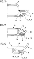
- an elevated support bed is provided with which the improved breakdown run can be further optimized (FIG. 10).
- FIG. 10 There is also the option of TU optimization (concentricity / tire uniformity). The concentricity of the tire is measured before the final attachment. According to this data, the bead in the chamber can be shifted in the axial direction by small distances, so that runout deviations are compensated for.
- the complete wheel according to the invention can also be advantageous use on vehicles with air suspension system.
- a retreading takes place with the complete wheel in the Way that you put the wheel in a heating mold or a Cold retreading is carried out.
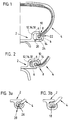
- the embodiment A shown in Fig. 1 wheel / tire combination according to the invention comprises a Special rim 2 and a special tire 4. (standard tire cannot be used because their bead area is different is designed.)
- the rim 2 has on both sides circular tubular rim flange 6 with one each lateral annular opening 8.
- the radially outward-facing side of the tubular rim flange 6 as emergency running surface 10.
- the upper (Version A, Fig. 1) or lower outer corner (version B, Fig. 2) of the tubular cavity 12 "missing", i. H. she represents the said annular opening 8.
- This opening 8 is so narrow that the bead 14 of the Tire 4 only in the rotated state through the opening 8 in the annular cavity 12 can be inserted. After Introducing the bead 14 into the cavity 12 rotates bead 14 previously twisted elastically into its starting position back and with its broad shape blocks the opening 8 of the cavity 12.
- the rim flange 6 has a Filling hole 20 at a suitable point. Alternatively, you can filling from the outside, 22, can also be carried out.
- FIGS. 5 to 11 represent further embodiment variants of the concept according to the invention.
- the filler material reduces the cross section of the open side of the cavity and thus prevents the tire bead from slipping out of the cavity.
- Figures 2, 5 and 7 show designs by the Design of the tubular rim flange and the Tire beads an increased puncture risk without have an additional support bed.
- Fig. 9 is shown in the here Embodiments do not twist the bead 14 to get it in to introduce the cavity 12 of the rim flange 6.
- the tire flank 30 is bent slightly here that the more or less transverse bead 14 is longitudinal through the opening 8 into the cavity 12 of the rim flange 6 can be introduced.
- the cross sections of Bead 14 and clear width of the rim flange 6 designed so that either a more bending of the tire flank 30 after a lighter inside or one more bend outside Insertion of the bead 14 into the cavity 12 allows.
- the cross section of the Cavity 12 and the cross section of the bead 14 so trained that the bead 14 as large as possible Length of contact with the inner surface of the cavity 12 having. In this way, a largely defined position of the Tire 4 given in relation to the rim 2.
- the arrow shown indicates the filling direction.
- the complete wheel described is produced as follows:
- the transverse bulge 14 is rotated in the longitudinal direction.
- the longitudinally turned bead 14 is inserted into the annular opening (joint) 8 of the tubular rim flange cavity 12, where it can turn back into its original transverse position due to the elastic prestress.
- the joint space 16 remaining in the cavity 12 of the rim flange 6 is filled with liquid curable material 18 (e.g. epoxy resin). Until the filled material 18 has hardened, the position of the bead 14 in the rim flange cavity 12 along the rim circumference can be changed in order to optimize the balancing (FIG. 4).
Landscapes
- Engineering & Computer Science (AREA)
- Mechanical Engineering (AREA)
- Tires In General (AREA)
- Heating, Cooling, Or Curing Plastics Or The Like In General (AREA)
- Pulleys (AREA)
- Tyre Moulding (AREA)
Abstract
Description
Auch wäre kein Widerspruch zwischen einem Langzeitreifen und dem erfindungsgemäßen integrierten Rad ersichtlich. Lediglich bei Nobelkarossen, "Oldtimern" und Fahrzeugen mit teuren Aluminiumrädern wird man in absehbarer Zeit auf eine manuelle Ummontage nicht verzichten wollen.
Bei Verzicht auf einen Stahlkern ergibt sich außer einer weiteren Gewichtseinsparung auch eine nicht unbeträchtliche Materialeinsparung.
Da das im Fahrbetrieb zu verformende Gummivolumen geringer ist, reduziert sich somit auch der Rollwiderstand.
Ein Abwerfen des Reifens ist unmöglich, da Reifen und Felge fest miteinander verbunden sind.
Das erfindungsgemäß integrierte Rad eröffnet vermehrt gestalterische Freiheiten.
Außerdem besteht die Möglichkeit der TU-Optimierung (Rundlauf / Tire Uniformity). Der Rundlauf des Reifens wird vor der endgültigen Befestigung gemessen. Entsprechend dieser Daten kann der Wulst in der Kammer in axialer Richtung um kleine Wegstrecken verschoben werden, so daß Rundlaufabweichungen ausgeglichen werden.
Das Füllmaterial verringert den Querschnitt der offenen Seite des Hohlraumes und verhindert somit das Herausrutschen des Reifenwulstes aus dem Hohlraum.
Der quer ausgebildete Wulst 14 wird in Längsrichtung gedreht. Dann wird der derartig längsgedrehte Wulst 14 in die ringförmige Öffnung (Fuge) 8 des rohrförmigen Felgenhornhohlraumes 12 eingeführt, wo er sich aufgrund der elastischen Vorspannung wieder in seine ursprüngliche Querlage zurückdrehen kann. Der in dem Hohlraum 12 des Felgenhorns 6 verbleibende Fugenraum 16 wird mit flüssigem aushärtbarem Werkstoff 18 (z. B. Epoxyharz) aufgefüllt. Bis zur Aushärtung des eingefüllten Werkstoffes 18 kann die Position des Wulstes 14 in dem Felgenhornhohlraum 12 entlang dem Felgenumfang zwecks Optimierung der Auswuchtung verändert werden (Fig. 4).
- 2
- (Spezial)felge
- 4
- (Spezial)reifen
- 6
- rohrförmiges Felgenhorn
- 8
- ringförmige Öffnung (Fuge)
- 10
- Notlauffläche
- 12
- Hohlraum des Felgenhorns
- 14
- Wulst
- 16
- (verbleibender) Fugenraum
- 18
- flüssiger aushärtbarer Werkstoff
- 20
- Füllbohrung
- 22
- "Füllen von außen"
- 24
- Wulstkern
- 26
- (Wulstkern-)Hohlraum
- 28
- "Injektion"
- 30
- Reifenflanke
- 32
- freies Ende des Felgenhorns
Claims (5)
- Fahrzeug-Komplettradmit einer Spezialfelge (2) undmit einem mit Wulst (14) ausgestatteten Spezialreifen (4), wobei die Felge (2) beidseitig ein kreisrundes Felgenhorn (6) aufweist,das zur Aufnahme des Wulstes (14) einen mit einer ringförmigen Öffnung (Fuge) (8) versehenen rohrförmigen Hohlraum (12) mit rechteckigem bis quadratischem Querschnitt bildet,
wobei die Breite dieser Öffnung (8) so eng bemessen ist, daS der Wulst (14) des Reifens (4) nur im längsgedrehten Zustand durch die Öffnung (8) in den ringförmigen Hohlraum (12) eingeführt werden kann,
dadurch gekennzeichnet,daß der nach Einfügen des Reifenwulstes (14) in dem rohrförmigen Hohlraum (12) des Felgenhorns (6) verbleibende Fugenraum (16) mit flüssigem aushärtbarem Werkstoff (18) auffüllbar ist. - Fahrzeug-Komplettradmit einer Spezialfelge (2) undmit einem mit Wulst (14) ausgestatteten Spezialreifen (4), wobei die Felge (2) beidseitig ein kreisrundes Felgenhorn (6) aufweist,das zur Aufnahme des Wulstes (14) einen mit einer ringförmigen Öffnung (Fuge) (8) versehenen rohrförmigen Hohlraum (12) mit rechteckigem bis quadratischem Querschnitt bildet,
dadurch gekennzeichnet,daß nach Einfügen des Reifenwulstes (14) in den rohrförmigen Hohlraum (12) ein Wulstkernhohlraum (26) durch Injektion (28) eines flüssigen aushärtbaren Werkstoffes (18) unter Druck soweit auffüllbar ist,daS der Wulst (14) den Felgenhornhohlraum (12) gänzlich ausfüllt und kein freier Fugenraum (16) mehr verbleibt. - Fahrzeug-Komplettrad nach Anspruch 1 oder 2,
dadurch gekennzeichnet,daß der flüssige aushärtbare Werkstoff (18) Epoxyharz, hochmoduliges Polymer, flüssiger Kunststoff oder Metall mit niedrigem Schmelzpunkt ist. - Fahrzeug-Komplettrad nach einem der Ansprüche 1 bis 3,
dadurch gekennzeichnet,daß die radial nach außen gerichtete Seite des rohrförmigen Felgenhornes (6) als erhöhtes Stützbett ausgebildet ist, wodurch es als Notlauffläche (10) dient. - Verfahren zur Herstellung einer aus Rad mit Spezialfelge (2) und Spezialreifen (4) bestehender Rad/Reifen-Anordnung nach einem der Ansprüche 1 - 4,
gekennzeichnet durch
folgende Verfahrensschritte:a) der breit geformte Wulst (14) des Reifens (4) wird durch Verdrehen der Breitseite gedreht;b) der derartig längsgedrehte Wulst (14) wird in die ringförmige Öffnung (Fuge) (8) des rohrförmigen Felgenhorn-Hohlraums (12) eingeführt, (wo er sich aufgrund der elastischen Vorspannung wieder in seine ursprüngliche Breite zurückdrehen kann);c1) der in dem Hohlraum (12) des Felgenhorns (6) verbleibende Fugenraum (16) wird durch eine Füllbohrung (20) oder durch die ringförmige Fuge (8) mit flüssigem aushärtbarem Werkstoff (18) aufgefüllt; oderc2) ein Wulstkern-Hohlraum (26) wird durch Injektion (28) mit flüssigem aushärtbarem Werkstoff (18) unter Druck so weit aufgefüllt, bis der Wulst (14) den Felgenhornhohlraum (12) gänzlich ausfüllt und kein freier Fugenraum (16) mehr verbleibt;d) vor Aushärtung des eingeführten Werkstoffs (18) wird die Position des Wulstes (14) in dem Felgenhorn-Hohlraum (12) entlang des Felgenumfangs zwecks Optimierung des Rundlaufs justiert.
Applications Claiming Priority (2)
| Application Number | Priority Date | Filing Date | Title |
|---|---|---|---|
| DE19714200A DE19714200C2 (de) | 1997-04-07 | 1997-04-07 | Fahrzeug-Komplettrad |
| DE19714200 | 1997-04-07 |
Publications (3)
| Publication Number | Publication Date |
|---|---|
| EP0870629A2 true EP0870629A2 (de) | 1998-10-14 |
| EP0870629A3 EP0870629A3 (de) | 2001-01-24 |
| EP0870629B1 EP0870629B1 (de) | 2003-10-08 |
Family
ID=7825615
Family Applications (1)
| Application Number | Title | Priority Date | Filing Date |
|---|---|---|---|
| EP98105697A Expired - Lifetime EP0870629B1 (de) | 1997-04-07 | 1998-03-28 | Fahrzeug-Komplettrad |
Country Status (5)
| Country | Link |
|---|---|
| US (1) | US6070632A (de) |
| EP (1) | EP0870629B1 (de) |
| JP (1) | JPH115406A (de) |
| AT (1) | ATE251553T1 (de) |
| DE (2) | DE19714200C2 (de) |
Families Citing this family (9)
| Publication number | Priority date | Publication date | Assignee | Title |
|---|---|---|---|---|
| US6267450B1 (en) * | 1998-07-06 | 2001-07-31 | Christopher L. Gamble | Load balancing system |
| DE19837712A1 (de) * | 1998-08-20 | 2000-03-02 | Continental Ag | Fahrzeugrad |
| DE19844368C2 (de) * | 1998-09-28 | 2000-10-19 | Continental Ag | Fahrzeugrad mit insbesondere einteiliger Felge und schlauchlosem Luftreifen, das insbesondere für Notlauf geeignet ist, und ein Verfahren zu seiner Montage |
| DE19855519A1 (de) * | 1998-12-02 | 2000-06-15 | Continental Ag | Fahrzeugrad mit - insbesondere einteiliger - Felge und schlauchlosem Luftreifen, das insbesondere für Notlauf geeignet ist, und eine Felge zum Einsatz in einem solchen Fahrzeugrad |
| DE19930939A1 (de) * | 1999-07-05 | 2001-01-18 | Continental Ag | Felge eines Fahrzeugrades für schlauchlose Luftreifen mit auf der radial äußeren Mantelfläche der Felge ausgebildeter Notlaufstützfläche |
| KR101215080B1 (ko) | 2010-09-01 | 2012-12-24 | 황윤철 | 형상변형바퀴 |
| WO2012008688A2 (ko) * | 2010-07-16 | 2012-01-19 | Yoo Hwa-Yale | 형상 변형 바퀴 |
| WO2016143189A1 (ja) * | 2015-03-09 | 2016-09-15 | 住友ゴム工業株式会社 | タイヤ |
| DE102018112852A1 (de) * | 2018-05-29 | 2019-12-05 | Arnold Jäger Holding GmbH | Rad, insbesondere für landwirtschaftliche Maschinen, sowie Verfahren zum Herstellen eines Rades |
Citations (6)
| Publication number | Priority date | Publication date | Assignee | Title |
|---|---|---|---|---|
| DE2937272A1 (de) | 1978-09-16 | 1980-03-27 | Dunlop Ltd | Luftreifen-radfelgenanordnung |
| DE3605803A1 (de) | 1986-02-22 | 1987-01-02 | Daimler Benz Ag | Fahrzeugrad |
| DE3601185A1 (de) | 1986-01-17 | 1987-07-23 | Erwin Hymer | Radsystem fuer luftbereifte fahrzeuge aller art |
| DE3733515A1 (de) | 1987-04-18 | 1989-04-13 | Klaue Hermann | Luftbereiftes rad fuer kraftfahrzeuge |
| DE3732590A1 (de) | 1987-04-18 | 1989-04-20 | Klaue Hermann | Luftbereiftes rad fuer kraftfahrzeuge |
| DE3809425A1 (de) | 1987-04-18 | 1989-10-12 | Klaue Hermann | Luftbereiftes rad fuer kraftfahrzeuge |
Family Cites Families (7)
| Publication number | Priority date | Publication date | Assignee | Title |
|---|---|---|---|---|
| US1932191A (en) * | 1931-01-27 | 1933-10-24 | Alvin H Shoemaker | Pneumatic tire and rim |
| US1903575A (en) * | 1932-02-24 | 1933-04-11 | Alvin H Shoemaker | Radial cord pneumatic tire |
| IT959778B (it) * | 1972-05-31 | 1973-11-10 | Pirelli | Metodo per bloccare una copertura pneumatica al cerchio e ruota pneumatica cosi ottenuta |
| DE3237544A1 (de) * | 1982-10-09 | 1984-04-12 | Continental Gummi-Werke Ag, 3000 Hannover | Abdeckring fuer ein fahrzeugrad |
| DE3635464A1 (de) * | 1986-10-18 | 1988-04-21 | Continental Gummi Werke Ag | Fuellring fuer ein luftbereiftes fahrzeugrad |
| DE3931675A1 (de) * | 1989-09-22 | 1991-04-04 | Continental Ag | Luftbereiftes fahrzeugrad |
| DE4032645A1 (de) * | 1989-11-03 | 1991-05-08 | Continental Ag | Luftbereiftes fahrzeugrad mit einer vorrichtung mit gleitmittelreservoir |
-
1997
- 1997-04-07 DE DE19714200A patent/DE19714200C2/de not_active Expired - Fee Related
-
1998
- 1998-03-28 AT AT98105697T patent/ATE251553T1/de not_active IP Right Cessation
- 1998-03-28 DE DE59809836T patent/DE59809836D1/de not_active Expired - Fee Related
- 1998-03-28 EP EP98105697A patent/EP0870629B1/de not_active Expired - Lifetime
- 1998-04-03 JP JP10092041A patent/JPH115406A/ja not_active Withdrawn
- 1998-04-07 US US09/056,552 patent/US6070632A/en not_active Expired - Fee Related
Patent Citations (6)
| Publication number | Priority date | Publication date | Assignee | Title |
|---|---|---|---|---|
| DE2937272A1 (de) | 1978-09-16 | 1980-03-27 | Dunlop Ltd | Luftreifen-radfelgenanordnung |
| DE3601185A1 (de) | 1986-01-17 | 1987-07-23 | Erwin Hymer | Radsystem fuer luftbereifte fahrzeuge aller art |
| DE3605803A1 (de) | 1986-02-22 | 1987-01-02 | Daimler Benz Ag | Fahrzeugrad |
| DE3733515A1 (de) | 1987-04-18 | 1989-04-13 | Klaue Hermann | Luftbereiftes rad fuer kraftfahrzeuge |
| DE3732590A1 (de) | 1987-04-18 | 1989-04-20 | Klaue Hermann | Luftbereiftes rad fuer kraftfahrzeuge |
| DE3809425A1 (de) | 1987-04-18 | 1989-10-12 | Klaue Hermann | Luftbereiftes rad fuer kraftfahrzeuge |
Also Published As
| Publication number | Publication date |
|---|---|
| ATE251553T1 (de) | 2003-10-15 |
| DE59809836D1 (de) | 2003-11-13 |
| EP0870629B1 (de) | 2003-10-08 |
| US6070632A (en) | 2000-06-06 |
| DE19714200C2 (de) | 1999-04-22 |
| EP0870629A3 (de) | 2001-01-24 |
| DE19714200A1 (de) | 1998-10-08 |
| JPH115406A (ja) | 1999-01-12 |
Similar Documents
| Publication | Publication Date | Title |
|---|---|---|
| DE19745409C2 (de) | Fahrzeugrad mit einem Notlaufstützkörper | |
| EP1094957A1 (de) | Fahrzeugrad mit einem notlaufstützkörper | |
| WO2001044002A1 (de) | Kraftfahrzeugbauteil | |
| EP0870629B1 (de) | Fahrzeug-Komplettrad | |
| DE69805277T2 (de) | Notlaufvorrichtung für auto und verfahren zu seiner montage | |
| DE2950718A1 (de) | Luftreifen-radfelgenanordnung | |
| DE69010274T2 (de) | Wulst-Spreizer. | |
| DE10208613C1 (de) | Fahrzeugrad mit einem Notlaufstützkörper | |
| EP0664228B1 (de) | Bereiftes Fahrzeugrad | |
| DE3611038A1 (de) | Leichtmetallrad mit abdeckplatte | |
| EP0168688A2 (de) | Fahrzeugrad | |
| DE2716737A1 (de) | Sicherheits-reifenabstuetzung fuer eine radfelge | |
| DE602004012697T2 (de) | Optimierte Felge und Rad mit solcher Felge | |
| DE4209687A1 (de) | Reifen für ein Fahrzeug, insbesondere für ein Kraftfahrzeug sowie Verfahren zu dessen Herstellung | |
| DE102019126369A1 (de) | Verfahren zur Ausrüstung eines Kraftfahrzeugs mit zumindest einer Radlaufabdeckung und Kraftfahrzeug mit zumindest einer Radlaufabdeckung | |
| DE102021210971A1 (de) | Kraftfahrzeugverbundbremstrommel für eine Kraftfahrzeugradbremse | |
| DE4104457C2 (de) | Vollreifen | |
| EP4405183B1 (de) | Scheibenrad für ein fahrzeug | |
| DE4310714A1 (de) | Luftreifen | |
| DE3734890A1 (de) | Bereiftes mehrteiliges fahrzeugrad | |
| EP1555052B1 (de) | Rad für ein Spielzeugmodell-Fahrzeug | |
| DE19941674A1 (de) | Felge, Rad mit einer solchen Felge und Verfahren zur Herstellung eines solchen Rades | |
| DE102018105299B4 (de) | Rad für ein Kraftfahrzeug | |
| DE102022110609A1 (de) | Radvorrichtung mit radial außenliegender Reifeneinheit sowie Verfahren und Verwendung | |
| DE3642036A1 (de) | Luftbereiftes fahrzeugrad mit gesichertem wulstsitz |
Legal Events
| Date | Code | Title | Description |
|---|---|---|---|
| PUAI | Public reference made under article 153(3) epc to a published international application that has entered the european phase |
Free format text: ORIGINAL CODE: 0009012 |
|
| AK | Designated contracting states |
Kind code of ref document: A2 Designated state(s): AT BE CH DE DK ES FI FR GB GR IE IT LI LU NL PT SE |
|
| AX | Request for extension of the european patent |
Free format text: AL;LT;LV;MK;RO;SI |
|
| PUAL | Search report despatched |
Free format text: ORIGINAL CODE: 0009013 |
|
| AK | Designated contracting states |
Kind code of ref document: A3 Designated state(s): AT BE CH DE DK ES FI FR GB GR IE IT LI LU MC NL PT SE |
|
| AX | Request for extension of the european patent |
Free format text: AL;LT;LV;MK;RO;SI |
|
| RIC1 | Information provided on ipc code assigned before grant |
Free format text: 7B 60B 21/02 A, 7B 60C 15/02 B |
|
| 17P | Request for examination filed |
Effective date: 20010724 |
|
| AKX | Designation fees paid |
Free format text: AT BE CH DE DK ES FI FR GB GR IE IT LI LU NL PT SE |
|
| 17Q | First examination report despatched |
Effective date: 20021015 |
|
| GRAH | Despatch of communication of intention to grant a patent |
Free format text: ORIGINAL CODE: EPIDOS IGRA |
|
| GRAS | Grant fee paid |
Free format text: ORIGINAL CODE: EPIDOSNIGR3 |
|
| GRAA | (expected) grant |
Free format text: ORIGINAL CODE: 0009210 |
|
| AK | Designated contracting states |
Kind code of ref document: B1 Designated state(s): AT BE CH DE DK ES FI FR GB GR IE IT LI LU NL PT SE |
|
| PG25 | Lapsed in a contracting state [announced via postgrant information from national office to epo] |
Ref country code: NL Free format text: LAPSE BECAUSE OF FAILURE TO SUBMIT A TRANSLATION OF THE DESCRIPTION OR TO PAY THE FEE WITHIN THE PRESCRIBED TIME-LIMIT Effective date: 20031008 Ref country code: IT Free format text: LAPSE BECAUSE OF FAILURE TO SUBMIT A TRANSLATION OF THE DESCRIPTION OR TO PAY THE FEE WITHIN THE PRESCRIBED TIME-LIMIT;WARNING: LAPSES OF ITALIAN PATENTS WITH EFFECTIVE DATE BEFORE 2007 MAY HAVE OCCURRED AT ANY TIME BEFORE 2007. THE CORRECT EFFECTIVE DATE MAY BE DIFFERENT FROM THE ONE RECORDED. Effective date: 20031008 Ref country code: IE Free format text: LAPSE BECAUSE OF FAILURE TO SUBMIT A TRANSLATION OF THE DESCRIPTION OR TO PAY THE FEE WITHIN THE PRESCRIBED TIME-LIMIT Effective date: 20031008 Ref country code: GB Free format text: LAPSE BECAUSE OF FAILURE TO SUBMIT A TRANSLATION OF THE DESCRIPTION OR TO PAY THE FEE WITHIN THE PRESCRIBED TIME-LIMIT Effective date: 20031008 Ref country code: FR Free format text: LAPSE BECAUSE OF FAILURE TO SUBMIT A TRANSLATION OF THE DESCRIPTION OR TO PAY THE FEE WITHIN THE PRESCRIBED TIME-LIMIT Effective date: 20031008 Ref country code: FI Free format text: LAPSE BECAUSE OF FAILURE TO SUBMIT A TRANSLATION OF THE DESCRIPTION OR TO PAY THE FEE WITHIN THE PRESCRIBED TIME-LIMIT Effective date: 20031008 |
|
| REG | Reference to a national code |
Ref country code: GB Ref legal event code: FG4D Free format text: NOT ENGLISH |
|
| REG | Reference to a national code |
Ref country code: CH Ref legal event code: EP |
|
| REG | Reference to a national code |
Ref country code: IE Ref legal event code: FG4D Free format text: GERMAN |
|
| REF | Corresponds to: |
Ref document number: 59809836 Country of ref document: DE Date of ref document: 20031113 Kind code of ref document: P |
|
| PG25 | Lapsed in a contracting state [announced via postgrant information from national office to epo] |
Ref country code: SE Free format text: LAPSE BECAUSE OF FAILURE TO SUBMIT A TRANSLATION OF THE DESCRIPTION OR TO PAY THE FEE WITHIN THE PRESCRIBED TIME-LIMIT Effective date: 20040108 Ref country code: GR Free format text: LAPSE BECAUSE OF FAILURE TO SUBMIT A TRANSLATION OF THE DESCRIPTION OR TO PAY THE FEE WITHIN THE PRESCRIBED TIME-LIMIT Effective date: 20040108 Ref country code: DK Free format text: LAPSE BECAUSE OF FAILURE TO SUBMIT A TRANSLATION OF THE DESCRIPTION OR TO PAY THE FEE WITHIN THE PRESCRIBED TIME-LIMIT Effective date: 20040108 |
|
| PG25 | Lapsed in a contracting state [announced via postgrant information from national office to epo] |
Ref country code: ES Free format text: LAPSE BECAUSE OF FAILURE TO SUBMIT A TRANSLATION OF THE DESCRIPTION OR TO PAY THE FEE WITHIN THE PRESCRIBED TIME-LIMIT Effective date: 20040119 |
|
| NLV1 | Nl: lapsed or annulled due to failure to fulfill the requirements of art. 29p and 29m of the patents act | ||
| PG25 | Lapsed in a contracting state [announced via postgrant information from national office to epo] |
Ref country code: LU Free format text: LAPSE BECAUSE OF NON-PAYMENT OF DUE FEES Effective date: 20040328 Ref country code: AT Free format text: LAPSE BECAUSE OF NON-PAYMENT OF DUE FEES Effective date: 20040328 |
|
| PG25 | Lapsed in a contracting state [announced via postgrant information from national office to epo] |
Ref country code: LI Free format text: LAPSE BECAUSE OF NON-PAYMENT OF DUE FEES Effective date: 20040331 Ref country code: CH Free format text: LAPSE BECAUSE OF NON-PAYMENT OF DUE FEES Effective date: 20040331 Ref country code: BE Free format text: LAPSE BECAUSE OF NON-PAYMENT OF DUE FEES Effective date: 20040331 |
|
| GBV | Gb: ep patent (uk) treated as always having been void in accordance with gb section 77(7)/1977 [no translation filed] |
Effective date: 20031008 |
|
| REG | Reference to a national code |
Ref country code: IE Ref legal event code: FD4D |
|
| PLBE | No opposition filed within time limit |
Free format text: ORIGINAL CODE: 0009261 |
|
| STAA | Information on the status of an ep patent application or granted ep patent |
Free format text: STATUS: NO OPPOSITION FILED WITHIN TIME LIMIT |
|
| 26N | No opposition filed |
Effective date: 20040709 |
|
| BERE | Be: lapsed |
Owner name: *CONTINENTAL A.G. Effective date: 20040331 |
|
| EN | Fr: translation not filed | ||
| REG | Reference to a national code |
Ref country code: CH Ref legal event code: PL |
|
| PGFP | Annual fee paid to national office [announced via postgrant information from national office to epo] |
Ref country code: DE Payment date: 20050323 Year of fee payment: 8 |
|
| PG25 | Lapsed in a contracting state [announced via postgrant information from national office to epo] |
Ref country code: DE Free format text: LAPSE BECAUSE OF NON-PAYMENT OF DUE FEES Effective date: 20061003 |
|
| PG25 | Lapsed in a contracting state [announced via postgrant information from national office to epo] |
Ref country code: PT Free format text: LAPSE BECAUSE OF NON-PAYMENT OF DUE FEES Effective date: 20040308 |