EP0869577A1 - Dispositif et procédé d'émission à diversité adaptive - Google Patents
Dispositif et procédé d'émission à diversité adaptive Download PDFInfo
- Publication number
- EP0869577A1 EP0869577A1 EP98105853A EP98105853A EP0869577A1 EP 0869577 A1 EP0869577 A1 EP 0869577A1 EP 98105853 A EP98105853 A EP 98105853A EP 98105853 A EP98105853 A EP 98105853A EP 0869577 A1 EP0869577 A1 EP 0869577A1
- Authority
- EP
- European Patent Office
- Prior art keywords
- reception
- radiation pattern
- transmission
- outputs
- processing systems
- Prior art date
- Legal status (The legal status is an assumption and is not a legal conclusion. Google has not performed a legal analysis and makes no representation as to the accuracy of the status listed.)
- Withdrawn
Links
Images


Classifications
-
- H—ELECTRICITY
- H04—ELECTRIC COMMUNICATION TECHNIQUE
- H04B—TRANSMISSION
- H04B7/00—Radio transmission systems, i.e. using radiation field
- H04B7/02—Diversity systems; Multi-antenna system, i.e. transmission or reception using multiple antennas
- H04B7/04—Diversity systems; Multi-antenna system, i.e. transmission or reception using multiple antennas using two or more spaced independent antennas
- H04B7/08—Diversity systems; Multi-antenna system, i.e. transmission or reception using multiple antennas using two or more spaced independent antennas at the receiving station
- H04B7/0837—Diversity systems; Multi-antenna system, i.e. transmission or reception using multiple antennas using two or more spaced independent antennas at the receiving station using pre-detection combining
- H04B7/0842—Weighted combining
- H04B7/086—Weighted combining using weights depending on external parameters, e.g. direction of arrival [DOA], predetermined weights or beamforming
-
- H—ELECTRICITY
- H01—ELECTRIC ELEMENTS
- H01Q—ANTENNAS, i.e. RADIO AERIALS
- H01Q3/00—Arrangements for changing or varying the orientation or the shape of the directional pattern of the waves radiated from an antenna or antenna system
- H01Q3/26—Arrangements for changing or varying the orientation or the shape of the directional pattern of the waves radiated from an antenna or antenna system varying the relative phase or relative amplitude of energisation between two or more active radiating elements; varying the distribution of energy across a radiating aperture
- H01Q3/2605—Array of radiating elements provided with a feedback control over the element weights, e.g. adaptive arrays
-
- H—ELECTRICITY
- H04—ELECTRIC COMMUNICATION TECHNIQUE
- H04B—TRANSMISSION
- H04B7/00—Radio transmission systems, i.e. using radiation field
- H04B7/02—Diversity systems; Multi-antenna system, i.e. transmission or reception using multiple antennas
- H04B7/04—Diversity systems; Multi-antenna system, i.e. transmission or reception using multiple antennas using two or more spaced independent antennas
- H04B7/06—Diversity systems; Multi-antenna system, i.e. transmission or reception using multiple antennas using two or more spaced independent antennas at the transmitting station
- H04B7/0613—Diversity systems; Multi-antenna system, i.e. transmission or reception using multiple antennas using two or more spaced independent antennas at the transmitting station using simultaneous transmission
- H04B7/0615—Diversity systems; Multi-antenna system, i.e. transmission or reception using multiple antennas using two or more spaced independent antennas at the transmitting station using simultaneous transmission of weighted versions of same signal
- H04B7/0617—Diversity systems; Multi-antenna system, i.e. transmission or reception using multiple antennas using two or more spaced independent antennas at the transmitting station using simultaneous transmission of weighted versions of same signal for beam forming
Definitions
- the present invention relates to a transmission diversity technique for spread spectrum communication, and, more particularly, to an adaptive transmission diversity apparatus capable of determining a transmission radiation pattern in accordance with a reception radiation pattern.
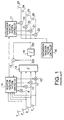
- FIG. 1 presents a block diagram showing the structure of a conventional adaptive transmission diversity apparatus
- FIG. 2 is a diagram illustrating the relationship between the incoming directions of radio waves and a reception radiation pattern.
- S 1 (t), S 2 (t), S 3 (t) and S 4 (t) denote complex signals, which have respectively been received at reception antennas 1, 2, 3 and 4 at time t and have then undergone A/D conversion and quasi-coherent detection.
- the outputs W 1 (t), W 2 (t), W 3 (t) and W 4 (t) of a reception radiation pattern controller 13 are respectively sent to multipliers 9, 10, 11 and 12 which in turn multiply the associated complex signals by the respective outputs.
- the multiplication outputs are then composed by an adder 14.
- the output, S(t), of the adder 14 then is given by the following formula (1).
- S ( t) 1 4 W i ( t ) S i ( t )
- the above process of multiplying signals, received at a plurality of antennas, by the proper complex numbers and then adding the resultant values allows the antennas as a whole to acquire radiation pattern on a plane.
- the reception radiation pattern controller 13 in FIG. 1 controls the radiation pattern as indicated by reference numeral "33" in FIG. 2, so that the desired signal can be received at a strong level and the interference signal at a weak level. This control can enhance the reception performance.
- a determination section 16 outputs a result D(t) of determining the composed signal S(t).
- An error detector 15 outputs a difference S(t)-D(t) between the composed signal S(t) and the determination result D(t).
- the reception radiation pattern controller 13 renew its output complex number weights W 1 (t), W 2 (t), W 3 (t) and W 4 (t) based on the output of the error detector 15 and the complex signals S 1 (t), S 2 (t), S 3 (t) and S 4 (t).
- a transmission radiation pattern controller 17 computes weight outputs for transmission in consideration of a frequency difference between transmission and reception, etc. based on the outputs of the reception radiation pattern controller 13.
- Multipliers 22, 21, 20 and 19 multiply the outputs of the transmission radiation pattern controller 17 by a signal from a transmission signal generator 18.
- Antennas 23, 24, 25 and 26 convert the signals from those multipliers to RF (Radio Frequency) band signals, and transmit the resultant signals.
- the above-described conventional time division and frequency division transmission diversity apparatuses have difficulty in detecting a directly arriving reception wave and an indirectly arriving reception wave reflected by buildings, mountains or the like and separating them from each other taking time shift into consideration. This makes it difficult to form a radiation pattern for each incoming wave, which results in a difficulty in controlling the transmission power with the radiation pattern that corresponds to the received wave.
- an object of the present invention to provide an adaptive transmission diversity apparatus which can detect radiation patterns of direct and indirect waves arriving in a time-shifted manner, and determine a proper transmission radiation pattern in accordance with the radiation patterns. It is another object of this invention to provide a specific reference for selecting a proper transmission radiation pattern.
- this invention provides an adaptive transmission diversity apparatus which employs a spread spectrum system, detects radiation patterns of direct and indirect waves having arrived in a time-shifted manner, by means of reception radiation controllers, and operates a transmission radiation controller in accordance with a transmission radiation pattern which is determined by selecting a proper one of the radiation patterns obtained by the reception radiation pattern controllers or combining those radiation patterns. This can ensure a higher transmission performance.
- An adaptive transmission diversity apparatus comprises a separating section for separating a received same signal per incoming wave; a reception radiation pattern generating section for determining reception directivities respectively for reception timings for the separated incoming waves; a transmission radiation pattern generating section for determining a transmission radiation pattern by selecting a proper one of, or combining, the reception radiation patterns; and a transmitting section for transmitting a signal in accordance with the transmission radiation pattern.
- An adaptive transmission diversity apparatus comprises a separating section for separating a reception signal into a direct wave and an indirect wave; a reception radiation pattern generating section for determining reception directivities respectively for reception timings for the separated direct wave and indirect wave; a transmission radiation pattern generating section for determining a transmission radiation pattern by selecting a proper one of, or combining, the reception radiation patterns; and a transmitting section for transmitting a signal in accordance with the transmission radiation pattern.
- the transmission radiation pattern can be controlled optimally with an improved transmission precision, and power consumption on the transmission side can be reduced. In this case, increasing the number of incoming waves to be caught can further enhance the transmission performance.
- selection of a proper one of the reception radiation patterns by the transmission radiation pattern generating section is carried out by comparing outputs of a plurality of reception signal processing systems, connected in parallel to an antenna, with one another. Further, in the adaptive transmission diversity apparatus according to the present invention, the outputs of the plurality of reception signal processing systems are compared with reception signal powers of the respective reception signal processing systems. Furthermore, in the adaptive transmission diversity apparatus according to this invention, the outputs of the plurality of reception signal processing systems are compared with ratios of desired signal power to interference signal power of the respective reception signal processing systems.
- the transmission radiation pattern can easily be acquired by generating a transmission radiation pattern based on the reception radiation pattern selected in the above manner.
- the use of reception signal power can further facilitate the acquisition of the transmission radiation pattern.
- the use of the ratios of desired signal power to interference signal power can allow the transmission radiation pattern to be obtained with a higher precision.
- combination of the reception radiation patterns by the transmission radiation pattern generating section is carried out based on either reception powers of outputs of a plurality of reception signal processing systems, connected in parallel to an antenna, or ratios of desired signal power to interference signal power of the reception signal processing systems.
- Combining the reception radiation patterns this way can provide a more proper transmission radiation pattern and can reduce interference on other transmission signals. Further, the transmission power can be suppressed, thus reducing the power consumption.
- An adaptive transmission diversity apparatus comprises a plurality of reception signal processing systems for multiplying respective output signals, acquired by despreading signals received at a plurality of antennas by means of matched filters,sliding correlator and so on, by respective output signals of reception radiation pattern controllers and then adding resultant signals together to provide an output; a composing section for Rake composing on outputs of the plurality of reception signal processing systems; an error detecting section for acquiring differences between an output of the composing section and the outputs of the reception signal processing systems; a controlling section for determining output values to be sent to said multipliers in the reception radiation pattern controllers from outputs of the error detector and outputs of the matched filters; a detecting section for inputting the outputs of the plurality of reception signal processing systems and computing reception signal powers or ratios of desired signal power to interference signal power; a transmission radiation pattern controller for inputting outputs of the detecting section and determining transmission directivities in accordance with an output of the reception radiation pattern controller of the reception signal processing
- An adaptive transmission diversity apparatus comprises a plurality of reception signal processing systems for multiplying respective output signals, acquired by despreading signals received at a plurality of antennas by means of matched filters, by respective output signals of reception radiation pattern controllers and then adding resultant signals together to provide an output; a composing section for Rake composing on outputs of the plurality of reception signal processing systems; an error detecting section for acquiring differences between an output of the composing section and the outputs of the reception signal processing systems; a controlling section for determining output values to be sent to said multipliers in the reception radiation pattern controllers from outputs of the error detecting section and outputs of the matched filters; a detector for receiving the outputs of the plurality of reception signal processing systems and computing reception signal powers or ratios of desired signal power to interference signal power ; a transmission radiation pattern controller for inputting outputs of the detecting section and determining transmission directivities by composing outputs of the plurality of reception radiation pattern controllers based on either the reception powers or the ratios of
- an adaptive transmission diversity method which comprises the steps of separating a received same signal per incoming wave; generating reception radiation patterns for determining reception directivities respectively for reception timings for the separated incoming waves; generating a transmission radiation pattern by selecting one of, or composing, the reception radiation patterns based on the incoming waves; and transmitting a signal in accordance with the generated transmission radiation pattern.
- This method can be implemented more surely and easily by separating a received same transmission signal per incoming wave by a plurality of reception signal processing systems connected in parallel to an antenna, and generating a radiation pattern based on results of performing comparison and determination on outputs of the plurality of reception signal processing systems.
- FIG. 3 is a block diagram showing the structure of an adaptive transmission diversity apparatus according to the first embodiment of this invention
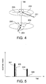
- FIG. 4 is a diagram depicting the relationship between the incoming directions of radio waves and a radiation pattern
- FIG. 5 is a diagram illustrating the relationship example between the arrival times of radio waves and power.
- signals received at a plurality of reception antennas 101, 102, 103 and 104 are subjected to A/D conversion and de-spread in matched filters 105, 106, 107 and 108.
- Multipliers 112, 111, 110 and 109 multiply the outputs of those matched filters 105 to 108 by the outputs of a reception radiation pattern controller 121.
- An adder 122 adds the outputs of the multipliers 109 to 112.
- Matched filters 113, 114, 115 and 116 perform A/D conversion and a de-spreading operation on the signals received at the antennas 101 to 104.
- Multipliers 117, 118, 119 and 120 multiply the outputs of the matched filters 113 to 116 by the outputs of a reception radiation pattern controller 124.
- An adder 125 adds the outputs of the multipliers 117 to 120.
- the parallel arrangement of similar reception signal processing systems is employed here to capture waves which arrive at different timings.
- a Rake device 126 is a circuit that Rake composes the output of the adder 122 and the output of the adder 125, and outputs the composed signal to a determining circuit 127.
- This determining circuit 127 makes a decision to restore Rake-composed (signal-processed) data to original signals of "1's" and "0's.”
- the output of the determining circuit 127 is output both to an error detector 123, which acquires a difference between the output of the determining circuit 127 and the output of the adder 122, and an error detector 138, which acquires a difference between the output of the determining circuit 127 and the output of the adder 125.
- the reception radiation pattern controller 121 controls values to be output to the multipliers 112 to 115 based on the outputs of the matched filters 105 to 108 and the output of the error detector 123.
- the reception radiation pattern controller 124 controls values to be output to the multipliers 117 to 120 based on the outputs of the matched filters 113 to 116 and the output of the error detector 138.
- Power detectors 139 and 140 compute powers of the reception signals from the outputs of the adders 122 and 125, respectively, and output to a transmission radiation pattern controller 128.
- This transmission radiation pattern controller 128 controls the transmission radiation pattern by selecting one of the outputs of the reception radiation pattern controllers 121 and 124 which shows greater reception power of the desired signal.
- a transmission signal output from a transmission signal generator 137 is composed with the output of the transmission radiation pattern controller 128 by multipliers 129, 130, 131 and 132, and resultant signals are transmitted from antennas 133, 134, 135 and 136.
- the amount of computation can be reduced by decreasing the number of antennas and the performance can be improved by increasing that number.
- the reception signals received at the reception antennas 101 to 104 undergo processes, such as band conversion to a base band from an RF (Radio Frequency) band or an IF (Intermediate Frequency) band and demodulation, before they are input to the matched filters 105 to 108.
- the matched filters 105 to 108 de-spread the input signals and send their outputs to the multipliers 112 to 109.
- the multipliers 109 to 112 multiply the outputs of the matched filters 105 to 108 by the output of the reception radiation pattern controller 121.
- the adder 122 adds the outputs of the multipliers 109 to 112 together.
- the matched filters 113 to 116 de-spread the inputted signals in such a way as to capture waves which arrive at different timings from those for the matched filters 105 to 108.
- the multipliers 117 to 120 respectively multiply the outputs of the matched filters 113 to 116 by the output of the reception radiation pattern controller 124.
- the adder 125 adds the outputs of the multipliers 117 to 120 together.
- the output of the adder 125, S 2 (t) can be expressed as the following formula (4):
- S 2 ( t ) 1 4 w * 2 i ( t ) T S 2 i ( t )
- the rake device 126 composes the outputs of the adders 122 and 125. This operation is performed in such a manner that the composed output S(t) becomes the maximum ratio as given by the following formula (5).
- S ( t ) 1 /
- the composing may be accomplished by using another method. Further, more incoming waves may be composed by using greater number of matched filters and reception radiation pattern controllers.
- the determining circuit 127 determines the composed reception signal. With the determination result being D(t), the error detectors 123 and 138 output differences between this determination result and the original signals. For example, the error detector 123 outputs D(t)-Sig 1 (t) to the reception radiation pattern controller 121, and the error detector 138 outputs D(t)-Sig 2 (t) to the reception radiation pattern controller 124. Based on those outputs, the reception radiation pattern controllers 121 and 124 renew their outputs.
- the output of the reception radiation pattern controller 121 should be set as given by the following formula (6).
- W 1 (t+1) W 1 (t)+ ⁇ (D(t)-Sig 1 (t)) T Sig 1 (t)
- the output of the reception radiation pattern controller 124 should be set as given by the following formula (7).
- W 2 (t+1) W 2 (t)+ ⁇ (D(t)-Sig 2 (t)) T Sig 2 (t)
- the transmission radiation pattern controller 128 acquire weights W 1 (t) and W 2 (t) from the reception radiation pattern controller 121 and the reception radiation pattern controller 124. For example, the transmission radiation pattern controller 128 computes W 1 (t) as a transmission weight when
- the reception radiation pattern controller 121 forms a radiation pattern as indicated by "202"
- the reception radiation pattern controller 124 forms a radiation pattern as indicated by "204”.
- arrows 205 and 206 indicate the incoming directions of interference signals at the respective timings.
- FIG. 5 shows the reception powers of individual incoming radio waves at this time.
- 301 shows the reception power of the desired signal that arrives at the timing of an arrow 301
- 303 shows the reception power of the desired signal that arrives at the timing of an arrow 303
- 305 and "306” show the reception powers of incoming interference signals.
- the transmission radiation pattern controller 121 compares the levels of the reception powers with one another, and selects "202" as the transmission radiation pattern as the reception power for the arrow 201 is greater.
- a control signal output from the transmission radiation pattern controller 128 and the transmission signal from the transmission signal generator 137 are composed by the multipliers 129 to 132.
- the composed signals are transmitted from the antennas 133 to 136.
- the transmission radiation pattern controller 128 performs frequency band conversion too.
- the transmission antennas 133 to 136 are designed as a time division multiplex or frequency division multiplex type, the transmission antennas 133 to 136 can be combined with the reception antennas.
- the transmission radiation pattern controller compares the levels of the reception powers of the reception signals with one another to determine the optimal transmission radiation pattern, thereby selecting the optimal radiation pattern and reducing interference on other transmission signals, so that the overall transmission power can be reduced.
- FIG. 6 is a block diagram showing the structure of the adaptive transmission diversity apparatus according to the second embodiment of the present invention. Since the structure of the adaptive transmission diversity apparatus according to the second embodiment is substantially the same as the structure shown in FIG. 3, same reference numerals are given to those components and methods to omit the detailed description.
- the structure shown in FIG. 6 differs from that shown in FIG. 3 in the structure of the use of SIR measuring units 439 and 440 as the transmission radiation pattern controller 128 and the power detectors for computing the powers of reception signals. While the powers of the reception signals are computed by reception signal powers
- the transmission radiation pattern controller 128 acquire weights W 1 (t) and W 2 (t) from the reception radiation pattern controller 121 and the reception radiation pattern controller 124 as the first embodiment.
- the reception radiation pattern controller 121 forms a radiation pattern as indicated by "202”
- the reception radiation pattern controller 124 forms a radiation pattern as indicated by "204.”
- the reception powers of individual incoming radio waves then are illustrated in FIG. 5.
- "301” shows the reception power of the desired signal that arrives at the timing of the arrow 201
- "303” shows the reception power of the desired signal that arrives at the timing of the arrow 203
- "305” and "306” show the reception powers of incoming interference signals.
- the output value of the SIR measuring unit 440 becomes greater than that of the SIR measuring unit 439, for example.
- the transmission radiation pattern controller 128 compares the ratios of the desired signal power to the interference signal power, calculated at the respective timings, with each other based on the outputs of the SIR measuring units 439 and 440 to thereby select the transmission radiation pattern 204.
- the control signal output from the transmission radiation pattern controller 128 and the transmission signal output from the transmission signal generator 137 are composed by the multipliers 129 to 132.
- the composed signals are transmitted from the antennas 133 to 136.
- the transmission radiation pattern controller determines the transmission radiation pattern based on the ratios of the powers of the desired signals in the reception signals to the interference signal powers, it is possible to form a transmission radiation pattern with a higher precision than is obtained in the first embodiment and to further reduce interference on other transmission signals.
- the transmission radiation pattern controller 128 measures the ratio of the desired signal power to the interference signal power at each timing, and composes the patterns from the reception radiation pattern controllers 121 and 124 in such a way that the ratio becomes maximum.
- the transmission radiation pattern controller 128 composes the transmission patterns (complex numbers to be given to the multipliers), Ws(t), as given by the following formula (8) by using the outputs W 1 (t) and W 2 (t) of the reception radiation pattern controllers 121 and 124 and the desired signal reception powers s1 and s2 at the respective timings.
- Ws ( t ) 1 / s 1+ s 2 ⁇ s 1 W 1( t )+ s 2 W 2( t ))
- the transmission radiation pattern controller can form a more optimal transmission radiation pattern by composing the reception radiation patterns that have been formed by the individual reception radiation pattern controllers, and can thus reduce interference on other transmission signals. Further, the transmission power can be suppressed, thus reducing the power consumption.
- a received same transmission signal is separated per incoming wave and a transmission radiation pattern is generated by selecting one of, or composing, the reception radiation patterns of the individual reception signal processing systems.
- This can ensure optimal control of the transmission radiation pattern, can improve the transmission precision and can reduce the power consumption on the transmission side.
- the transmission performance can be improved by capturing a larger number of incoming waves according to this invention.
- the transmission radiation pattern can be acquired easily by generating the transmission radiation pattern based on the selected reception radiation pattern.
- the use of the reception signal power in this case can further facilitate the acquisition of the transmission radiation pattern.
- the use of the ratio of the desired signal power to the interference signal power can allow the transmission radiation pattern to be obtained with a higher accuracy.
- composing the reception radiation patterns can permit the formation of a more optimal transmission radiation pattern and can further reduce interference on other transmission signals. It is also possible to suppress transmission power, which results in lower power consumption.
Landscapes
- Engineering & Computer Science (AREA)
- Computer Networks & Wireless Communication (AREA)
- Signal Processing (AREA)
- Radio Transmission System (AREA)
- Mobile Radio Communication Systems (AREA)
- Variable-Direction Aerials And Aerial Arrays (AREA)
Applications Claiming Priority (2)
| Application Number | Priority Date | Filing Date | Title |
|---|---|---|---|
| JP99640/97 | 1997-04-02 | ||
| JP09964097A JP3300252B2 (ja) | 1997-04-02 | 1997-04-02 | 適応送信ダイバーシチ装置及び適応送信ダイバーシチ方法 |
Publications (1)
| Publication Number | Publication Date |
|---|---|
| EP0869577A1 true EP0869577A1 (fr) | 1998-10-07 |
Family
ID=14252667
Family Applications (1)
| Application Number | Title | Priority Date | Filing Date |
|---|---|---|---|
| EP98105853A Withdrawn EP0869577A1 (fr) | 1997-04-02 | 1998-03-31 | Dispositif et procédé d'émission à diversité adaptive |
Country Status (5)
| Country | Link |
|---|---|
| US (1) | US6240149B1 (fr) |
| EP (1) | EP0869577A1 (fr) |
| JP (1) | JP3300252B2 (fr) |
| KR (1) | KR100323600B1 (fr) |
| CN (2) | CN1097361C (fr) |
Cited By (7)
| Publication number | Priority date | Publication date | Assignee | Title |
|---|---|---|---|---|
| EP1001557A2 (fr) * | 1998-11-10 | 2000-05-17 | Matsushita Electric Industrial Co., Ltd. | Station de base et procédé de radiocommunication avec diversité |
| DE19943688A1 (de) * | 1999-09-06 | 2001-04-12 | Hertz Inst Heinrich | Verfahren und Anordnung zur Strahlformung für den Downlink-Kanal in CDMA-basierten Mobilfunksystemen |
| WO2002003571A1 (fr) * | 2000-07-03 | 2002-01-10 | Matsushita Electric Industrial Co., Ltd. | Dispositif et procede de communication sans fil |
| US6590532B1 (en) | 1999-06-23 | 2003-07-08 | Japan As Represented By President Of Hokkaido University | Radio device |
| US6771984B1 (en) | 1998-08-03 | 2004-08-03 | Matsushita Electric Industrial Co., Ltd. | Base station device and radio communication method |
| EP2438648A1 (fr) * | 2009-02-19 | 2012-04-11 | Polyvalor, Limited Partnership | Système permettant de contrôler le diagramme de rayonnement d'une antenne directionnelle |
| EP3662703A4 (fr) * | 2017-11-17 | 2020-08-05 | Samsung Electronics Co., Ltd. | Dispositif électronique et procédé de régulation de puissance dans un dispositif électronique |
Families Citing this family (23)
| Publication number | Priority date | Publication date | Assignee | Title |
|---|---|---|---|---|
| JPH11298400A (ja) * | 1998-04-10 | 1999-10-29 | Nec Saitama Ltd | 適応アンテナの指向性制御回路及び指向性制御方法 |
| JP3092798B2 (ja) * | 1998-06-30 | 2000-09-25 | 日本電気株式会社 | 適応送受信装置 |
| FR2788179B1 (fr) * | 1998-12-31 | 2003-06-20 | Cit Alcatel | Satellite a couverture omnidirectionnelle |
| DE19901877B4 (de) * | 1999-01-19 | 2005-10-13 | Siemens Ag | Verfahren zum Gewinnen von Informationen über Störungen im Empfänger eines Nachrichtenübertragungssystems |
| JP3641961B2 (ja) | 1999-02-01 | 2005-04-27 | 株式会社日立製作所 | アダプティブアレイアンテナを使用した無線通信装置 |
| US7120431B1 (en) * | 1999-02-12 | 2006-10-10 | Lucent Technologies Inc. | System and method for adjusting antenna radiation in a wireless network |
| SE516105C2 (sv) * | 1999-06-11 | 2001-11-19 | Allgon Ab | En metod för att styra strålningsmönstret hos en antenn, ett antennsystem och en radiokommunikationsanordning |
| JP3554226B2 (ja) * | 1999-06-18 | 2004-08-18 | 松下電器産業株式会社 | 受信装置 |
| US6667715B1 (en) * | 1999-08-18 | 2003-12-23 | Hughes Electronics Corporation | Signal processing circuit for communicating with a modular mobile satellite terminal and method therefor |
| US6628969B1 (en) * | 1999-09-07 | 2003-09-30 | Kenneth F. Rilling | One-tuner adaptive array |
| KR100592596B1 (ko) * | 1999-12-24 | 2006-06-26 | 한국전자통신연구원 | 적응형 전송 시스템에서의 전송 방식 선택 방법 |
| US6920192B1 (en) * | 2000-08-03 | 2005-07-19 | Lucent Technologies Inc. | Adaptive antenna array methods and apparatus for use in a multi-access wireless communication system |
| JP2002151937A (ja) * | 2000-11-15 | 2002-05-24 | Nec Corp | 適応アレーアンテナ受信装置 |
| KR100651973B1 (ko) * | 2000-12-20 | 2006-11-30 | 엘지전자 주식회사 | 안테나 어레이를 구비한 시스템에 적용되는 신호대 잡음비 추정 방법 및 이를 위한 장치 |
| JP4569015B2 (ja) * | 2001-02-28 | 2010-10-27 | ソニー株式会社 | 広帯域アレイアンテナ |
| US7099380B1 (en) | 2001-11-16 | 2006-08-29 | Marvell International Ltd. | Apparatus for antenna diversity for wireless communication and method thereof |
| JP3956739B2 (ja) * | 2002-03-27 | 2007-08-08 | 日本電気株式会社 | マルチビームアンテナ送受信装置及び送受信方法並びに送信ビーム選択方法 |
| JP4134597B2 (ja) * | 2002-05-23 | 2008-08-20 | 日本電気株式会社 | 適応アンテナ送受信装置 |
| US6968170B2 (en) | 2002-07-16 | 2005-11-22 | Narad Networks, Inc. | Adaptive correction of a received signal frequency response tilt |
| US7155176B2 (en) * | 2004-04-08 | 2006-12-26 | Skyworks Solutions, Inc. | System for synchronizing a portable transceiver to a network |
| JP4571032B2 (ja) * | 2005-07-14 | 2010-10-27 | 株式会社エヌ・ティ・ティ・ドコモ | Cdmaシステムにおける基地局および送受信方法 |
| KR100981495B1 (ko) * | 2005-10-12 | 2010-09-10 | 삼성전자주식회사 | 통신 시스템에서 데이터 송신 방법 및 장치 |
| CN101227214B (zh) * | 2007-01-15 | 2011-04-20 | 中国移动通信集团设计院有限公司 | 一种码分多址系统的智能天线设置方法 |
Citations (4)
| Publication number | Priority date | Publication date | Assignee | Title |
|---|---|---|---|---|
| EP0595247A1 (fr) * | 1992-10-28 | 1994-05-04 | Atr Optical And Radio Communications Research Laboratories | Dispositif et procédé pour commander un réseau d'antennes avec une pluralité d'éléments d'antenne |
| WO1997000543A1 (fr) * | 1995-06-16 | 1997-01-03 | Watkins-Johnson Company | Procede et appareil de formation de faisceau d'emission adaptative dans un systeme de communications sans fils |
| WO1997009793A1 (fr) * | 1995-09-04 | 1997-03-13 | Matsushita Electric Industrial Co., Ltd. | Dispositif de communication mobile a radiotransmission numerique a etalement de spectre |
| EP0837523A2 (fr) * | 1996-10-18 | 1998-04-22 | Kabushiki Kaisha Toshiba | Antenne adaptative |
Family Cites Families (11)
| Publication number | Priority date | Publication date | Assignee | Title |
|---|---|---|---|---|
| CA2037824C (fr) * | 1990-03-20 | 1999-11-09 | Hiroshi Kubo | Circuit fonctionnant en diversite et circuit d'evaluation de la phase de trame (ou du temps d'echantillonnage) utilisant ce circuit |
| US5260968A (en) * | 1992-06-23 | 1993-11-09 | The Regents Of The University Of California | Method and apparatus for multiplexing communications signals through blind adaptive spatial filtering |
| JP2635503B2 (ja) | 1992-10-28 | 1997-07-30 | 株式会社エイ・ティ・アール光電波通信研究所 | アレーアンテナの制御方法及び制御装置 |
| JP2663820B2 (ja) * | 1992-12-28 | 1997-10-15 | 日本電気株式会社 | 判定帰還形等化器 |
| US5351274A (en) * | 1993-08-20 | 1994-09-27 | General Electric Company | Post detection selection combining diversity receivers for mobile and indoor radio channels |
| CA2151284C (fr) * | 1994-02-10 | 2000-04-25 | Kazuhiko Fukawa | Recepteur d'etalement de spectre adaptatif |
| JP2561031B2 (ja) * | 1994-06-07 | 1996-12-04 | 日本電気株式会社 | 送受信装置 |
| US5748683A (en) * | 1994-12-29 | 1998-05-05 | Motorola, Inc. | Multi-channel transceiver having an adaptive antenna array and method |
| JPH08316772A (ja) | 1995-05-19 | 1996-11-29 | Meidensha Corp | 圧電デバイス |
| JP3598609B2 (ja) * | 1995-09-20 | 2004-12-08 | 双葉電子工業株式会社 | スペクトル拡散通信システムにおける受信装置 |
| JPH10200444A (ja) * | 1997-01-06 | 1998-07-31 | Sony Corp | 受信装置、受信方法、無線システムの端末装置 |
-
1997
- 1997-04-02 JP JP09964097A patent/JP3300252B2/ja not_active Expired - Fee Related
-
1998
- 1998-03-31 EP EP98105853A patent/EP0869577A1/fr not_active Withdrawn
- 1998-03-31 CN CN98106120A patent/CN1097361C/zh not_active Expired - Fee Related
- 1998-04-01 US US09/052,976 patent/US6240149B1/en not_active Expired - Lifetime
- 1998-04-02 KR KR1019980011665A patent/KR100323600B1/ko not_active IP Right Cessation
-
2002
- 2002-10-30 CN CNB021482446A patent/CN1198408C/zh not_active Expired - Fee Related
Patent Citations (4)
| Publication number | Priority date | Publication date | Assignee | Title |
|---|---|---|---|---|
| EP0595247A1 (fr) * | 1992-10-28 | 1994-05-04 | Atr Optical And Radio Communications Research Laboratories | Dispositif et procédé pour commander un réseau d'antennes avec une pluralité d'éléments d'antenne |
| WO1997000543A1 (fr) * | 1995-06-16 | 1997-01-03 | Watkins-Johnson Company | Procede et appareil de formation de faisceau d'emission adaptative dans un systeme de communications sans fils |
| WO1997009793A1 (fr) * | 1995-09-04 | 1997-03-13 | Matsushita Electric Industrial Co., Ltd. | Dispositif de communication mobile a radiotransmission numerique a etalement de spectre |
| EP0837523A2 (fr) * | 1996-10-18 | 1998-04-22 | Kabushiki Kaisha Toshiba | Antenne adaptative |
Non-Patent Citations (3)
| Title |
|---|
| NOBORU KUROIWA ET AL: "DESIGN OF A DIRECTIONAL DIVERSITY RECEIVER USING AN ADAPTIVE ARRAY ANTENNA", ELECTRONICS & COMMUNICATIONS IN JAPAN, PART I - COMMUNICATIONS, vol. 74, no. 7, 1 July 1991 (1991-07-01), pages 87 - 97, XP000270241 * |
| TAKEO OHGANE: "SPECTRAL EFFICIENCY IMPROVEMENT BY BASE STATION ANTENNA PATTERN CONTROL FOR LAND MOBILE CELLULAR SYSTEMS", IEICE TRANSACTIONS ON COMMUNICATIONS, vol. E77-B, no. 5, 1 May 1995 (1995-05-01), pages 598 - 605, XP000540889 * |
| TORRIERI D ET AL: "BLIND ADAPTATION USING MAXIMIN ALGORITHM", PROCEEDINGS OF THE ASILOMAR CONFERENCE ON SIGNALS, SYSTEMS AND COMPUTERS, PACIFIC GROVE, NOV. 1 - 3, 1993, vol. VOL. 1, no. CONF. 27, 1 November 1993 (1993-11-01), INSTITUTE OF ELECTRICAL AND ELECTRONICS ENGINEERS, pages 638 - 642, XP000463774 * |
Cited By (13)
| Publication number | Priority date | Publication date | Assignee | Title |
|---|---|---|---|---|
| US6771984B1 (en) | 1998-08-03 | 2004-08-03 | Matsushita Electric Industrial Co., Ltd. | Base station device and radio communication method |
| EP1001557A2 (fr) * | 1998-11-10 | 2000-05-17 | Matsushita Electric Industrial Co., Ltd. | Station de base et procédé de radiocommunication avec diversité |
| EP1001557A3 (fr) * | 1998-11-10 | 2003-05-14 | Matsushita Electric Industrial Co., Ltd. | Station de base et procédé de radiocommunication avec diversité |
| US6721367B1 (en) | 1998-11-10 | 2004-04-13 | Matsushita Electric Industrial Co., Ltd. | Base station apparatus and radio communication method |
| US6590532B1 (en) | 1999-06-23 | 2003-07-08 | Japan As Represented By President Of Hokkaido University | Radio device |
| DE19943688A1 (de) * | 1999-09-06 | 2001-04-12 | Hertz Inst Heinrich | Verfahren und Anordnung zur Strahlformung für den Downlink-Kanal in CDMA-basierten Mobilfunksystemen |
| DE19943688C2 (de) * | 1999-09-06 | 2001-09-13 | Hertz Inst Heinrich | Verfahren und Anordnung zur Strahlformung für den Downlink-Kanal in CDMA-basierten Mobilfunksystemen |
| WO2002003571A1 (fr) * | 2000-07-03 | 2002-01-10 | Matsushita Electric Industrial Co., Ltd. | Dispositif et procede de communication sans fil |
| EP2438648A1 (fr) * | 2009-02-19 | 2012-04-11 | Polyvalor, Limited Partnership | Système permettant de contrôler le diagramme de rayonnement d'une antenne directionnelle |
| EP2438648A4 (fr) * | 2009-02-19 | 2014-06-25 | Polyvalor Ltd Partnership | Système permettant de contrôler le diagramme de rayonnement d'une antenne directionnelle |
| US9246238B2 (en) | 2009-02-19 | 2016-01-26 | Polyvalor, Limited Partnership | System for controlling a radiation pattern of a directional antenna |
| EP3662703A4 (fr) * | 2017-11-17 | 2020-08-05 | Samsung Electronics Co., Ltd. | Dispositif électronique et procédé de régulation de puissance dans un dispositif électronique |
| US11178614B2 (en) | 2017-11-17 | 2021-11-16 | Samsung Electronics Co., Ltd | Electronic device and method of controlling power in electronic device |
Also Published As
| Publication number | Publication date |
|---|---|
| KR19980081039A (ko) | 1998-11-25 |
| JP3300252B2 (ja) | 2002-07-08 |
| CN1198408C (zh) | 2005-04-20 |
| CN1423430A (zh) | 2003-06-11 |
| CN1097361C (zh) | 2002-12-25 |
| JPH10285092A (ja) | 1998-10-23 |
| US6240149B1 (en) | 2001-05-29 |
| CN1195240A (zh) | 1998-10-07 |
| KR100323600B1 (ko) | 2002-03-08 |
Similar Documents
| Publication | Publication Date | Title |
|---|---|---|
| US6240149B1 (en) | Adaptive transmission diversity apparatus and adaptive transmission diversity method | |
| US6385181B1 (en) | Array antenna system of wireless base station | |
| US7505509B2 (en) | Receiving communication apparatus using array antenna | |
| US6879624B2 (en) | Adaptive antenna receiver | |
| EP1191709B1 (fr) | Appareil recepteur a spectre disperse | |
| KR100428709B1 (ko) | 다중 경로 정보 피드백을 이용한 순방향 빔형성 장치 및그 방법 | |
| EP0825727A1 (fr) | Récepteur de type RAKE | |
| US6498928B1 (en) | Radio reception apparatus and method for detecting reception timing | |
| JP2003506994A (ja) | スマート・アンテナおよび干渉キャンセレーションに基づいたベースバンド処理方法 | |
| US7151792B2 (en) | Spread spectrum rake receiver | |
| US6771984B1 (en) | Base station device and radio communication method | |
| US20020072343A1 (en) | Receiver | |
| US6118806A (en) | Signal synthesis method and apparatus under diversity reception | |
| EP1336254B1 (fr) | Recepteur a recombinaison d'echos et procede permettant de fournir une estimation d'erreur de frequence | |
| KR100770498B1 (ko) | 스마트 안테나 및 이의 빔 형성 방법과 장치 | |
| US7116999B2 (en) | Mobile communications receiving apparatus and method | |
| KR100679435B1 (ko) | 초기단계부터 지향성 빔의 우수한 수신품질을 갖는 적응형안테나 수신 장치 | |
| EP1229667A2 (fr) | Sélection des trajets de propagation multiple par l'élimination et la détection successive des autocorrelations élevées | |
| EP1328072A1 (fr) | Récepteur à spectre étalé pour la liason descendant à diversité d'antenne de transmission | |
| US20020176487A1 (en) | Fading pitch measuring apparatus, fading pitch measuring method and portable information terminal using them | |
| KR100554922B1 (ko) | 다중 빔 기반의 다중경로 탐색장치 및 방법 | |
| US20030076876A1 (en) | Method of performing code synchronization, and receiver | |
| JP3030230B2 (ja) | 拡散通信システムの受信装置 | |
| KR970060574A (ko) | 배열안테나 및 그 설계방법과, 배열안테나에서의 신호 처리 방법과, 그를 이용한 신호 송수신장치 및 방법 | |
| KR100933412B1 (ko) | 다이버시티 안테나의 이동평균 경로지연 오프셋 보정장치및 그 운용방법 |
Legal Events
| Date | Code | Title | Description |
|---|---|---|---|
| PUAI | Public reference made under article 153(3) epc to a published international application that has entered the european phase |
Free format text: ORIGINAL CODE: 0009012 |
|
| AK | Designated contracting states |
Kind code of ref document: A1 Designated state(s): DE FR GB |
|
| 17P | Request for examination filed |
Effective date: 19980903 |
|
| 17Q | First examination report despatched |
Effective date: 19981130 |
|
| AKX | Designation fees paid |
Free format text: DE FR GB |
|
| GRAP | Despatch of communication of intention to grant a patent |
Free format text: ORIGINAL CODE: EPIDOSNIGR1 |
|
| STAA | Information on the status of an ep patent application or granted ep patent |
Free format text: STATUS: THE APPLICATION IS DEEMED TO BE WITHDRAWN |
|
| 18D | Application deemed to be withdrawn |
Effective date: 20050720 |