EP0867313B1 - Hülsengummifeder mit hydraulischer Dämpfung - Google Patents
Hülsengummifeder mit hydraulischer Dämpfung Download PDFInfo
- Publication number
- EP0867313B1 EP0867313B1 EP98102491A EP98102491A EP0867313B1 EP 0867313 B1 EP0867313 B1 EP 0867313B1 EP 98102491 A EP98102491 A EP 98102491A EP 98102491 A EP98102491 A EP 98102491A EP 0867313 B1 EP0867313 B1 EP 0867313B1
- Authority
- EP
- European Patent Office
- Prior art keywords
- bearing sleeve
- rubber
- hydraulic damping
- channel plate
- sleeve
- Prior art date
- Legal status (The legal status is an assumption and is not a legal conclusion. Google has not performed a legal analysis and makes no representation as to the accuracy of the status listed.)
- Expired - Lifetime
Links
- 238000013016 damping Methods 0.000 title claims description 25
- 229920001971 elastomer Polymers 0.000 claims description 39
- 239000000806 elastomer Substances 0.000 claims description 12
- 239000000872 buffer Substances 0.000 claims description 4
- 238000007789 sealing Methods 0.000 claims description 4
- 230000000295 complement effect Effects 0.000 claims description 3
- 239000012528 membrane Substances 0.000 description 7
- 239000003795 chemical substances by application Substances 0.000 description 3
- 239000000463 material Substances 0.000 description 3
- 238000009413 insulation Methods 0.000 description 2
- 238000004519 manufacturing process Methods 0.000 description 2
- 239000004033 plastic Substances 0.000 description 2
- 229920003023 plastic Polymers 0.000 description 2
- 230000007704 transition Effects 0.000 description 2
- 238000004073 vulcanization Methods 0.000 description 2
- 230000001419 dependent effect Effects 0.000 description 1
- 238000006073 displacement reaction Methods 0.000 description 1
- 239000012530 fluid Substances 0.000 description 1
- 239000002184 metal Substances 0.000 description 1
- 230000035515 penetration Effects 0.000 description 1
Images
Classifications
-
- F—MECHANICAL ENGINEERING; LIGHTING; HEATING; WEAPONS; BLASTING
- F16—ENGINEERING ELEMENTS AND UNITS; GENERAL MEASURES FOR PRODUCING AND MAINTAINING EFFECTIVE FUNCTIONING OF MACHINES OR INSTALLATIONS; THERMAL INSULATION IN GENERAL
- F16F—SPRINGS; SHOCK-ABSORBERS; MEANS FOR DAMPING VIBRATION
- F16F13/00—Units comprising springs of the non-fluid type as well as vibration-dampers, shock-absorbers, or fluid springs
- F16F13/04—Units comprising springs of the non-fluid type as well as vibration-dampers, shock-absorbers, or fluid springs comprising both a plastics spring and a damper, e.g. a friction damper
- F16F13/06—Units comprising springs of the non-fluid type as well as vibration-dampers, shock-absorbers, or fluid springs comprising both a plastics spring and a damper, e.g. a friction damper the damper being a fluid damper, e.g. the plastics spring not forming a part of the wall of the fluid chamber of the damper
- F16F13/08—Units comprising springs of the non-fluid type as well as vibration-dampers, shock-absorbers, or fluid springs comprising both a plastics spring and a damper, e.g. a friction damper the damper being a fluid damper, e.g. the plastics spring not forming a part of the wall of the fluid chamber of the damper the plastics spring forming at least a part of the wall of the fluid chamber of the damper
- F16F13/14—Units of the bushing type, i.e. loaded predominantly radially
Definitions
- the invention relates to a sleeve rubber spring with hydraulic damping.
- Such Sleeve rubber spring according to the preamble of claim 1 is disclosed in US-A-4,789,144 disclosed.
- Hydraulically damping bearings are used to reduce vibrations in the Automobile manufacturing known. However, they differ depending on the specific application the damping characteristics to be met.
- Sleeve rubber springs with hydraulic Insulation is designed for insulation in the axial or radial direction. In order to be able to absorb both directions of vibration, two separate ones must be used Components are used.
- a one-piece sleeve rubber spring with hydraulic Damping for motor vehicle bearings proposed.
- This consists of a inner bearing sleeve, an outer surrounding this with a radial distance Bearing sleeve, an elastomer body arranged between the two bearing sleeves, the forms at least one first chamber filled with hydraulic damping means.
- the material for the elastomer body or the sleeve rubber spring can for example rubber can be used. This is in different degrees of hardness can be used so that different damping characteristics are achieved can be. Of course, plastics can also be used.
- the elastomer body can also be reinforced with inserts made of metal and / or plastic become.
- a channel plate containing a throttle channel connecting the chambers separates the first chamber of a second chamber, which is within a the Sleeve rubber spring sealing cap is located.
- the outer bearing sleeve has at least two different outer diameters of which the mainly radially loaded area of smaller diameter in a motor vehicle component is used.
- the corresponding area of the inner Bearing sleeve is arranged with at least two distributed over the circumference Provide bumpers. These take over the damping of the Vehicle vibrations in the radial direction and are on the elastomer body formed.
- the area of the larger diameter contains the separated by the channel plate, chambers filled with damping agent, which are mainly used to dampen the Vibrations introduced into the axial direction of the sleeve rubber spring.
- damping agent which are mainly used to dampen the Vibrations introduced into the axial direction of the sleeve rubber spring.
- the collar also serves as a limit stop for the sleeve rubber spring receiving motor vehicle component when installed in the motor vehicle.
- the Bund should advantageously on its side facing the motor vehicle component with be coated with an elastomer layer.
- the displacement of the damping chambers in the area of the larger diameter has the advantage that a sleeve rubber spring according to the flow can be designed almost arbitrarily.
- the area of the larger diameter is not used according to the invention in a motor vehicle component, so that There are no geometric limits to the design, which means that the Outside diameter is almost freely selectable.
- the cross-section of the throttle duct can thus also damping characteristics be expanded or reduced. It is therefore an executable according to needs Sleeve rubber spring with variable volume or buckling stiffness in the Ratio of the diameter of the throttle channel reached.
- the channel plate of a sleeve rubber spring according to the invention can be divided into several parts, in particular be made in two parts. It then assigns one, for example Carrier part with the throttle channel and a lid closing this.
- the Carrier part can be made in one piece with a membrane, the radially inner Sealing area in a complementary receptacle of the inner bearing sleeve is used. This membrane mainly dampens vibrations smaller Amplitudes.
- the multi-part design of the channel plate has the advantage that during assembly of a sleeve rubber spring according to the invention air pockets are avoided can, which would influence the damping characteristics unintentionally.
- Such Components are known to be installed in a bath of damping fluid.
- a one-part throttle duct design there is therefore the risk that air bubbles in remain in the channel and thus during assembly in the sleeve rubber spring be included.
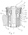
- FIG. 1 shows a possible embodiment of an example Sleeve rubber spring according to the invention shown in section.
- Such a one-piece sleeve rubber spring with hydraulic damping for bearings in motor vehicles consists of an inner bearing sleeve (1), one this with a radial spacing outer bearing sleeve (2), one between two bearing sleeves arranged elastomer body (3), one with hydraulic Has damping agent filled first chamber (4).
- the material for the elastomer body (3) of the sleeve rubber spring is present Rubber used. This can be used in different degrees of hardness, so too this enables different damping characteristics to be achieved.
- a channel plate (7) separates the first chamber (4) from a second chamber (6) within a cap sealingly sealing the sleeve rubber spring (5) located.
- the channel plate (7) contains a chamber (4 and 6) connecting Throttle channel (7.1).
- the outer bearing sleeve (2) has two different outer diameters, from which the mainly radially loaded area of smaller diameter in the Motor vehicle component (8) is used.
- the corresponding area of the inner Bearing sleeve (1) is provided with two stop buffers distributed over the circumference (9.1 and 9.2). These take over the damping of vehicle vibrations in the radial direction and are molded onto the elastomer body (3).
- the sleeve rubber spring has a radially outwardly directed collar (10).
- This covenant also serves as a limit stop for the Sleeve rubber spring receiving motor vehicle component (8) when installed in the Motor vehicle.
- the collar (10) is on its the motor vehicle component (8) facing side covered with an elastomer layer.
- the channel plate (7) of a sleeve rubber spring according to the invention is in two parts executed. It has a carrier part (7.2) with the throttle channel (7.1) and one this closing lid (7.3).
- the carrier part (7.2) is in one piece with a Diaphragm (7.4) executed, the radially inner area in a complementary Recording the inner bearing sleeve (1) is inserted sealingly.
- the membrane (7.4) mainly dampens vibrations of small amplitudes.
- the membrane (7.4) and carrier part (7.2) are through a vulcanization process inextricably linked.
Landscapes
- Engineering & Computer Science (AREA)
- General Engineering & Computer Science (AREA)
- Mechanical Engineering (AREA)
- Combined Devices Of Dampers And Springs (AREA)
- Arrangement Or Mounting Of Propulsion Units For Vehicles (AREA)
- Fluid-Damping Devices (AREA)
Description
- 1
- innere Lagerhülse
- 2
- äußere Lagerhülse
- 3
- Elastomerkörper
- 4
- erste Kammer
- 5
- Kappe
- 6
- zweite Kammer
- 7
- Kanalplatte
- 7.1
- Drosselkanal
- 7.2
- Trägerteil
- 7.3
- Deckel
- 7.4
- Membran
- 8
- Kraftfahrzeugbauteil
- 9.1
- Anschlagpuffer
- 9.2
- Anschlagpuffer
- 10
- Bund
Claims (2)
- Hülsengummifeder mit hydraulischer Dämpfung für Lagerungen in Kraftfahrzeugen, bestehend aus:dadurch gekennzeichnet, daß die äußere Lagerhülse (2) wenigstens zwei unterschiedliche Außendurchmesser aufweist, von denen der hauptsächlich radial belastete Bereich kleineren Durchmessers in ein Kraftfahrzeugbauteil (8) eingesetzt wird, auf dem korrespondierenden Bereich der inneren Lagerhülse (1) wenigstens zwei über den Umfang verteilt angeordnete Anschlagpuffer (9) vorgesehen sind und der Bereich größeren Durchmessers die durch die Kanalplatte (7) getrennten, mit Dämpfungsmittel gefüllten Kammern (4,6) enthält.einer inneren Lagerhülse (1),einer diese mit radialem Abstand umgebenden äußeren Lagerhülse (2),einem zwischen beiden Lagerhülsen an wenigstens einer festhaftend angeordneten Elastomerkörper (3), der wenigstens eine, mit hydraulischem Dämpfungsmittel gefüllte Kammer (4) bildet,einer Kappe (5), die die Hülsengummifeder unter Bildung einer zweiten Kammer (6) dichtend verschließt,einer Kanalplatte (7), die einen die Kammern (4 und 6) verbindenden Drosselkanal (7.1) enthält,
- Hülsengummifeder mit hydraulischer Dämpfung nach Anspruch 1,
dadurch gekennzeichnet, daß
die zweiteilige Kanalplatte (7) einen Trägerteil (7.2) mit dem Drosselkanal (7.1) sowie einen diesen verschließenden Deckel (7.3) aufweist und der Trägerteil (7.2) einstückig mit einer Membran (7.4) ausgeführt ist, deren radial innerer Bereich in eine komplementäre Aufnahme der inneren Lagerhülse (1) dichtend eingesetzt ist.
Applications Claiming Priority (2)
| Application Number | Priority Date | Filing Date | Title |
|---|---|---|---|
| DE19713003 | 1997-03-27 | ||
| DE19713003A DE19713003A1 (de) | 1997-03-27 | 1997-03-27 | Hülsengummifeder mit hydraulischer Dämpfung |
Publications (3)
| Publication Number | Publication Date |
|---|---|
| EP0867313A2 EP0867313A2 (de) | 1998-09-30 |
| EP0867313A3 EP0867313A3 (de) | 2001-03-21 |
| EP0867313B1 true EP0867313B1 (de) | 2002-05-08 |
Family
ID=7824865
Family Applications (1)
| Application Number | Title | Priority Date | Filing Date |
|---|---|---|---|
| EP98102491A Expired - Lifetime EP0867313B1 (de) | 1997-03-27 | 1998-02-13 | Hülsengummifeder mit hydraulischer Dämpfung |
Country Status (6)
| Country | Link |
|---|---|
| US (1) | US6029961A (de) |
| EP (1) | EP0867313B1 (de) |
| JP (1) | JPH10306839A (de) |
| BR (1) | BR9801131A (de) |
| DE (2) | DE19713003A1 (de) |
| ES (1) | ES2175540T3 (de) |
Families Citing this family (19)
| Publication number | Priority date | Publication date | Assignee | Title |
|---|---|---|---|---|
| JP3725346B2 (ja) * | 1998-09-02 | 2005-12-07 | 東洋ゴム工業株式会社 | 防振マウント |
| DE19936014C2 (de) * | 1999-08-04 | 2003-04-03 | Zf Lemfoerder Metallwaren Ag | Gummilager mit axialer Dämpfung |
| DE10146154B4 (de) | 2001-09-19 | 2007-04-26 | Trelleborg Automotive Technical Centre Gmbh | Hydraulisch dämpfende Buchse |
| DE10153921A1 (de) * | 2001-11-02 | 2003-05-22 | Paguag Gmbh | Elastomerlager |
| DE10222217A1 (de) * | 2002-05-16 | 2003-12-04 | Freudenberg Carl Kg | Gummilager |
| JP4110567B2 (ja) * | 2002-07-04 | 2008-07-02 | 東海ゴム工業株式会社 | 流体封入式筒形防振装置 |
| DE10359340A1 (de) | 2003-12-16 | 2005-07-28 | Zf Friedrichshafen Ag | Hydraulisch dämpfendes Buchsenlager |
| CA2533817C (en) * | 2005-01-26 | 2012-12-18 | The Pullman Company | Hydraulically damped body mount with bolt-through construction |
| KR100809035B1 (ko) * | 2006-05-17 | 2008-03-04 | (주)디티알 | 부시형 유체봉입식 고무 마운트 및 그 제조방법 |
| US8231115B2 (en) * | 2006-07-19 | 2012-07-31 | The Pullman Company | Very high damping body mount, subframe mount or engine mount with bolt-through construction |
| US8177201B2 (en) * | 2006-07-19 | 2012-05-15 | The Pullman Company | Very high damping mount with bolt-through construction |
| DE102007016399B4 (de) * | 2007-04-03 | 2009-12-31 | Zf Friedrichshafen Ag | Biaxial dämpfendes Hydrolager |
| US9038997B2 (en) | 2008-02-05 | 2015-05-26 | Cooper-Standard Automotive Inc. | Axially damped hydraulic mount assembly |
| CA2715251C (en) * | 2008-02-05 | 2016-05-17 | Cooper-Standard Automotive Inc. | Axially damped hydraulic mount assembly |
| US9765845B2 (en) | 2008-02-05 | 2017-09-19 | Cooper-Standard Automotive Inc. | Axially damped hydraulic mount assembly |
| KR101246008B1 (ko) * | 2009-07-29 | 2013-03-20 | 혼다 기켄 고교 가부시키가이샤 | 차량용 진동원 부착 구조 |
| DE102012213447A1 (de) | 2012-07-31 | 2014-02-06 | Zf Friedrichshafen Ag | Hydraulisch dämpfendes Buchsenlager |
| DE102012213446A1 (de) | 2012-07-31 | 2014-02-06 | Zf Friedrichshafen Ag | Hydraulisch dämpfendes Buchsenlager |
| CN104405824B (zh) * | 2014-10-13 | 2016-04-13 | 安徽奥丰汽车配件有限公司 | 汽车驾驶室悬置减震器 |
Family Cites Families (17)
| Publication number | Priority date | Publication date | Assignee | Title |
|---|---|---|---|---|
| DE3612436A1 (de) * | 1986-04-12 | 1987-10-15 | Boge Gmbh | Hydraulisch daempfendes motorlager, gummilager oder dergleichen |
| DE3882824T2 (de) * | 1987-06-17 | 1994-01-05 | Btr Plc | Elastische Buchse mit Fluiddämpfung. |
| US5005810A (en) * | 1987-07-09 | 1991-04-09 | Tokai Rubber Ind., Ltd. | Fluid-filled cushioning device having sealing arrangement for easy assembling |
| JPH01118231U (de) * | 1987-09-08 | 1989-08-10 | ||
| DE3818287A1 (de) * | 1988-05-30 | 1989-12-07 | Boge Ag | Hydraulisch daempfendes gummilager |
| JPH0749098Y2 (ja) * | 1989-07-25 | 1995-11-13 | 東海ゴム工業株式会社 | サスペンション用アッパサポート |
| FR2658257B1 (fr) * | 1990-02-15 | 1992-06-12 | Peugeot | Articulation hydroelastique a double effet a armatures concentriques. |
| FR2658256B1 (fr) * | 1990-02-15 | 1992-06-12 | Peugeot | Articulation hydroelastique a armatures concentriques. |
| JPH0442937U (de) * | 1990-08-09 | 1992-04-13 | ||
| DE4033519A1 (de) * | 1990-10-22 | 1992-04-23 | Freudenberg Carl Fa | Stuetzlager fuer einen stossdaempfer |
| US5277410A (en) * | 1991-02-21 | 1994-01-11 | Tokai Rubber Industries, Ltd. | Upper support for suspension system having two outer rigid members, and method of manufacturing the same |
| JP2678707B2 (ja) * | 1992-06-01 | 1997-11-17 | 東海ゴム工業株式会社 | 流体封入式筒型防振組立体 |
| US5845895A (en) * | 1993-09-08 | 1998-12-08 | Kabushiki Kaisha Komatsu Seisakusho | Liquid sealed rubber mount |
| JPH07269634A (ja) * | 1994-03-31 | 1995-10-20 | Kinugawa Rubber Ind Co Ltd | 防振部材の加締構造 |
| FR2727179B1 (fr) * | 1994-11-17 | 1997-01-17 | Hutchinson | Perfectionnements aux supports antivibratoires hydrauliques |
| JPH08177945A (ja) * | 1994-12-21 | 1996-07-12 | Tokai Rubber Ind Ltd | 流体封入式筒型防振装置 |
| JPH0968253A (ja) * | 1995-08-31 | 1997-03-11 | Kinugawa Rubber Ind Co Ltd | 液体封入式防振装置の製造方法 |
-
1997
- 1997-03-27 DE DE19713003A patent/DE19713003A1/de not_active Withdrawn
-
1998
- 1998-02-13 ES ES98102491T patent/ES2175540T3/es not_active Expired - Lifetime
- 1998-02-13 EP EP98102491A patent/EP0867313B1/de not_active Expired - Lifetime
- 1998-02-13 DE DE59804016T patent/DE59804016D1/de not_active Expired - Lifetime
- 1998-02-25 US US09/030,364 patent/US6029961A/en not_active Expired - Lifetime
- 1998-03-25 JP JP10077307A patent/JPH10306839A/ja active Pending
- 1998-03-26 BR BR9801131-6A patent/BR9801131A/pt not_active IP Right Cessation
Also Published As
| Publication number | Publication date |
|---|---|
| ES2175540T3 (es) | 2002-11-16 |
| EP0867313A2 (de) | 1998-09-30 |
| DE19713003A1 (de) | 1998-10-01 |
| JPH10306839A (ja) | 1998-11-17 |
| US6029961A (en) | 2000-02-29 |
| MX9802433A (es) | 1998-09-30 |
| EP0867313A3 (de) | 2001-03-21 |
| BR9801131A (pt) | 1999-10-13 |
| DE59804016D1 (de) | 2002-06-13 |
Similar Documents
| Publication | Publication Date | Title |
|---|---|---|
| DE19713003A1 (de) | Hülsengummifeder mit hydraulischer Dämpfung | |
| DE69006230T2 (de) | Oberes Lager für Stossdämpfer in Aufhängungssystemen. | |
| DE4305173C2 (de) | Hydraulisch dämpfende Lagerbuchse | |
| EP0547306B1 (de) | Deckel für Brennkraftmaschinen | |
| EP1160483B1 (de) | Hydrolager | |
| DE69618126T2 (de) | Elastisches Lager mit Befestigungssystem das als Haltemechanismus funktioniert und Methode zu dessen Fertigung | |
| DE4140854C2 (de) | Zylindrische, elastische Lagerung mit einer Fluidfüllung | |
| DE69010732T2 (de) | Oberes Lager für einen Stossdämpfer in einem Aufhängungssystem. | |
| DE3416431A1 (de) | Hydraulisch daempfendes gummilager | |
| EP2142821B1 (de) | Hydraulisch dämpfende elastomerbuchse | |
| DE69013257T2 (de) | Obere Halterung für einen Radaufhängungsstossdämpfer mit elastisch gelagertem Resonanzglied. | |
| DE19919189C2 (de) | Federbeinlager | |
| DE2932478A1 (de) | Hydrolager | |
| DE10118229A1 (de) | Hydraulisch dämpfendes Buchsenlager | |
| DE102020121886A1 (de) | KFZ-Lenksäulenlagerung | |
| DE102019007526A1 (de) | Hydraulisch dämpfendes Buchsenlager | |
| DE19537462C2 (de) | Aggregatelager | |
| EP1770303B1 (de) | Elastomerlager mit hydraulischer Dämpfung | |
| DE3829907A1 (de) | Montageeinheit aus elastomerem material mit hydraulischer daempfung fuer einen motor | |
| DE10041359B4 (de) | Elastisches Lager | |
| DE69016525T2 (de) | Flüssigkeitsgefülltes, zylindrisch-elastisches Lager mit ringförmiger Flüssigkeitskammer gleicher Querschnittsfläche. | |
| EP1908987A2 (de) | Elastische Lagerbuchse mit hydraulischer Dämpfung | |
| DE102018220654A1 (de) | Dämpfventilanordnung, insbesondere für einen Schwingungsdämpfer | |
| DE102017205836A1 (de) | Elastomerlager | |
| DE102010029055A1 (de) | Drehschwingungstilger für hohe Drehzahlen |
Legal Events
| Date | Code | Title | Description |
|---|---|---|---|
| PUAI | Public reference made under article 153(3) epc to a published international application that has entered the european phase |
Free format text: ORIGINAL CODE: 0009012 |
|
| AK | Designated contracting states |
Kind code of ref document: A2 Designated state(s): DE ES FR GB IT SE |
|
| AX | Request for extension of the european patent |
Free format text: AL;LT;LV;MK;RO;SI |
|
| RAP1 | Party data changed (applicant data changed or rights of an application transferred) |
Owner name: ZF LEMFOERDER METALLWAREN AG |
|
| PUAL | Search report despatched |
Free format text: ORIGINAL CODE: 0009013 |
|
| AK | Designated contracting states |
Kind code of ref document: A3 Designated state(s): AT BE CH DE DK ES FI FR GB GR IE IT LI LU MC NL PT SE |
|
| AX | Request for extension of the european patent |
Free format text: AL;LT;LV;MK;RO;SI |
|
| 17P | Request for examination filed |
Effective date: 20010419 |
|
| GRAG | Despatch of communication of intention to grant |
Free format text: ORIGINAL CODE: EPIDOS AGRA |
|
| GRAG | Despatch of communication of intention to grant |
Free format text: ORIGINAL CODE: EPIDOS AGRA |
|
| GRAH | Despatch of communication of intention to grant a patent |
Free format text: ORIGINAL CODE: EPIDOS IGRA |
|
| 17Q | First examination report despatched |
Effective date: 20011001 |
|
| AKX | Designation fees paid |
Free format text: DE ES FR GB IT SE |
|
| GRAH | Despatch of communication of intention to grant a patent |
Free format text: ORIGINAL CODE: EPIDOS IGRA |
|
| REG | Reference to a national code |
Ref country code: GB Ref legal event code: IF02 |
|
| GRAA | (expected) grant |
Free format text: ORIGINAL CODE: 0009210 |
|
| AK | Designated contracting states |
Kind code of ref document: B1 Designated state(s): DE ES FR GB IT SE |
|
| GBT | Gb: translation of ep patent filed (gb section 77(6)(a)/1977) |
Effective date: 20020509 |
|
| REF | Corresponds to: |
Ref document number: 59804016 Country of ref document: DE Date of ref document: 20020613 |
|
| ET | Fr: translation filed | ||
| REG | Reference to a national code |
Ref country code: ES Ref legal event code: FG2A Ref document number: 2175540 Country of ref document: ES Kind code of ref document: T3 |
|
| PLBE | No opposition filed within time limit |
Free format text: ORIGINAL CODE: 0009261 |
|
| STAA | Information on the status of an ep patent application or granted ep patent |
Free format text: STATUS: NO OPPOSITION FILED WITHIN TIME LIMIT |
|
| 26N | No opposition filed |
Effective date: 20030211 |
|
| PGFP | Annual fee paid to national office [announced via postgrant information from national office to epo] |
Ref country code: ES Payment date: 20080324 Year of fee payment: 11 |
|
| PGFP | Annual fee paid to national office [announced via postgrant information from national office to epo] |
Ref country code: SE Payment date: 20080219 Year of fee payment: 11 Ref country code: IT Payment date: 20080226 Year of fee payment: 11 Ref country code: GB Payment date: 20080213 Year of fee payment: 11 |
|
| PGFP | Annual fee paid to national office [announced via postgrant information from national office to epo] |
Ref country code: FR Payment date: 20080208 Year of fee payment: 11 |
|
| EUG | Se: european patent has lapsed | ||
| GBPC | Gb: european patent ceased through non-payment of renewal fee |
Effective date: 20090213 |
|
| REG | Reference to a national code |
Ref country code: FR Ref legal event code: ST Effective date: 20091030 |
|
| REG | Reference to a national code |
Ref country code: ES Ref legal event code: FD2A Effective date: 20090214 |
|
| PG25 | Lapsed in a contracting state [announced via postgrant information from national office to epo] |
Ref country code: GB Free format text: LAPSE BECAUSE OF NON-PAYMENT OF DUE FEES Effective date: 20090213 Ref country code: FR Free format text: LAPSE BECAUSE OF NON-PAYMENT OF DUE FEES Effective date: 20090302 |
|
| PGFP | Annual fee paid to national office [announced via postgrant information from national office to epo] |
Ref country code: DE Payment date: 20100226 Year of fee payment: 13 |
|
| PG25 | Lapsed in a contracting state [announced via postgrant information from national office to epo] |
Ref country code: ES Free format text: LAPSE BECAUSE OF NON-PAYMENT OF DUE FEES Effective date: 20090214 |
|
| PG25 | Lapsed in a contracting state [announced via postgrant information from national office to epo] |
Ref country code: IT Free format text: LAPSE BECAUSE OF NON-PAYMENT OF DUE FEES Effective date: 20090213 |
|
| PG25 | Lapsed in a contracting state [announced via postgrant information from national office to epo] |
Ref country code: SE Free format text: LAPSE BECAUSE OF NON-PAYMENT OF DUE FEES Effective date: 20090214 |
|
| REG | Reference to a national code |
Ref country code: DE Ref legal event code: R119 Ref document number: 59804016 Country of ref document: DE Effective date: 20110901 |
|
| PG25 | Lapsed in a contracting state [announced via postgrant information from national office to epo] |
Ref country code: DE Free format text: LAPSE BECAUSE OF NON-PAYMENT OF DUE FEES Effective date: 20110901 |