EP0865939A2 - Radschraube und Radmutter zur Befestigung von Kraftfahrzeugrädern - Google Patents
Radschraube und Radmutter zur Befestigung von Kraftfahrzeugrädern Download PDFInfo
- Publication number
- EP0865939A2 EP0865939A2 EP97110820A EP97110820A EP0865939A2 EP 0865939 A2 EP0865939 A2 EP 0865939A2 EP 97110820 A EP97110820 A EP 97110820A EP 97110820 A EP97110820 A EP 97110820A EP 0865939 A2 EP0865939 A2 EP 0865939A2
- Authority
- EP
- European Patent Office
- Prior art keywords
- wheel
- bolt
- nut
- diameter
- conical
- Prior art date
- Legal status (The legal status is an assumption and is not a legal conclusion. Google has not performed a legal analysis and makes no representation as to the accuracy of the status listed.)
- Withdrawn
Links
Images


Classifications
-
- B—PERFORMING OPERATIONS; TRANSPORTING
- B60—VEHICLES IN GENERAL
- B60B—VEHICLE WHEELS; CASTORS; AXLES FOR WHEELS OR CASTORS; INCREASING WHEEL ADHESION
- B60B3/00—Disc wheels, i.e. wheels with load-supporting disc body
- B60B3/14—Attaching disc body to hub ; Wheel adapters
- B60B3/16—Attaching disc body to hub ; Wheel adapters by bolts or the like
Definitions
- the invention enters a wheel bolt and a wheel nut for fastening motor vehicle wheels, wherein the wheel bolt has a nut part, an external thread shaft part and has a conical part located between them and the wheel rim in a threaded hole in the wheel hub or washer can be screwed in and the wheel nut Has counter thread and a cone part and one on the outer threaded shaft part the wheel rim can be screwed on through the wheel bolt or wheel hub.
- Vehicle wheel manufacturers today manufacture a wide variety of wheels from where the proportion of light alloy wheels is increasing due to the weight saving, which differ with regard to the rim dimensions, especially what their diameter and breadth in terms of satisfying diverse customer requests and fulfilling technical Differentiate requirements, for example in their bolt circle diameters for fastening the wheels or rims using wheel bolts and / or wheel nuts the wheel hub or disc.
- Unit wheel systems are already used to reduce manufacturing and warehousing costs have been proposed (EP 0 641 677, DE-A1-40 23 912, DE-U1-90 05 110), which based on a narrow alloy wheel, which can be used with a few additional elements, Connect connecting parts and interchangeable adapter parts to the wheel hub and can therefore be used on practically any car whose wheel hub has a bolt circle diameter of has about 98 to 122 mm.
- the present invention sees its task in simplifying the wheel fastening systems to achieve in a more cost-effective manner, especially in those cases where the bolt circle differences of different wheels or wheel flanges are not significant, so that the possibility is created to have wheels with the same bolt circle on wheel flanges to attach different bolt circles.
- the cone part of the wheel bolt and the wheel nut is a separate conical washer that fits onto the wheel bolt or wheel bolt or the wheel nut is attachable and has a through hole, the diameter is larger from the outside diameter of the threaded shaft part of the wheel bolt or the wheel bolt or the wheel nut.
- the largest outside diameter is the conical washer is larger than the outer diameter of the wheel nut flange, and the wheel nut has a shaft-shaped extension on which the conical disk is attachable.
- the outer diameter of this shaft-shaped extension is then expediently 1.5 to 2.5 mm smaller than the inside diameter of the conical disk.
- the invention enables the wheel bolt and the wheel nut for wheels with the same bolt circles on wheel flanges or discs or -Hubs with different bolt circles can be used because of the separate conical disc due to their play in the screw or nut holes of the bolt circle of the rim if the nut or screw is due to the difference in the hole circle diameter cannot reach through the hole centrally with the thread in the wheel flange or Wheel disc to engage.
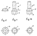
- the conventional wheel bolt 2 shown in FIG. 13 has a nut part 8, a threaded shaft part 4 and a cone part 9 which together form a unit.
- the wheel bolt serves as well as the conventional wheel nut 13 shown in FIGS. 14 and 15 or 21, which also has a conical part 9 firmly connected to the nut part 16, for conventional fastening of aluminum or steel wheels to motor vehicles.
- At 1 are only the usual nut part 6, provided with a End flange 7, and the threaded switching part 4 present, while the cone part, as shown in Fig. 2 can be seen as a separate conical disk 10 which has a clearance bore 11, with which it is pushed over the cylindrical part 5 of the wheel nut.
- the game this game hole is about 2 cm, d. H. their inner diameter is larger by this value as the associated wheel bolt or wheel nut of the type shown in Fig. 5, in the following will be discussed.
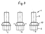
- a multi-use screw is created, which is characterized by that due to the lateral play of the conical disc, as shown in FIGS. 3 and 4 and indicated by the arrows, wheels with the same bolt circle on wheel flanges with different ones Bolt circles can be attached, the total play is approx. 2 mm, d. that is, in the event that the deviation of the bolt circle from the wheel or the wheel rim and wheel hub or disc is not larger than 2 mm, due to the lateral mobility the cone disc, this deviation can be compensated and a fastening of such Wheels on these wheel hubs are easily done.
- Fiat and VW vehicles usually with different bolt circles on the vehicle are equipped with the same wheels using this innovative wheel bolt can be without mounting or strength problems on the vehicles or their wheels occur.
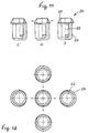
- the wheel nut can also be seen from FIG. 5 12 are provided with a separate conical disk 17 shown in FIG. 6, the Through hole 18 in turn allows lateral play when the conical disk has been plugged onto the shaft-shaped extension 19 of the wheel nut 12, which surrounds the internal thread 14 cylindrically, which, as usual, is in the nut part 15 continues.
- Fig. 7 is similar to Fig. 3 with the representations a, b and c, the lateral movement the wheel nut 12, as well as in FIG. 8.
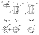
- the wheel or the rim must therefore be fastened by means of wheel bolts, possibly in place of the wheel nut 12 also find a wheel nut of the type designated 20 in FIG. 9, which does not has shaft-shaped extension, but at its bottom with a smooth flange piece 26 completes, while the nut part 23 and the internal thread 22 essentially correspond to the relevant parts of the wheel nut 12 shown in FIG. 5.
- the conical disk 24, as shown in FIG. 10, is a separately manufactured one Part, the bore 25 with respect to the wheel bolt on which the conical disc is placed has a clearance fit, i.e. laterally by approx. 2 mm in relation to the longitudinal axis of the bolt can move to center with the hole in question of the rim bolt circle To engage.
- FIGS. 11 and 12 The lateral mobility of this wheel nut 20 is in turn in FIGS. 11 and 12 Arrows marked, which correspond to FIGS. 7 and 8.
Landscapes
- Engineering & Computer Science (AREA)
- Mechanical Engineering (AREA)
- Connection Of Plates (AREA)
- Machines For Laying And Maintaining Railways (AREA)
- Arrangement Or Mounting Of Propulsion Units For Vehicles (AREA)
Abstract
Description
- Fig. 1
- eine Seitenansicht sowie eine zugehörige Draufsicht der erfindungsgemäßen Radschraube,
- Fig. 2
- eine Seitenansicht sowie eine zugehörige Draufsicht der zu der Radschraube von Fig. 1 gehörenden separaten Konusscheibe,
- Fig. 3
- eine schematisch Seitenansicht der Radschraube mit aufgesteckter Konusscheibe, wobei die mit a, b und c gekennzeichneten Darstellungen die seitliche Beweglichkeit der Konusscheibe in Bezug auf die Radschraube kennzeichnen,
- Fig. 4
- eine Draufsicht der mit den Konusscheiben versehenen Radschrauben gemäß Fig. 3 zur weiteren Verdeutlichung der seitlichen Beweglichkeit der Konusscheibe,
- Fig. 5
- eine teilweise längsgeschnittene Seitenansicht der Radmutter sowie eine Draufsicht dieser Mutter,
- Fig. 6
- eine teilweise längsgeschnittene Seitenansicht der zur Radmutter von Fig. 5 gehörenden Konusscheibe sowie eine Draufsicht der Konusscheibe,
- Fig. 7
- eine Seitenansicht der teilweise längsgeschnittenen Radmutter von Fig. 5 komplettiert mit der Konusscheibe von Fig. 6, die mit den mit a, b und c gekennzeichneten Darstellungen die seitliche Beweglichkeit der Konusscheibe in Bezug auf die Mutter verdeutlicht,
- Fig. 8
- eine der Fig. 7 entsprechende Draufsieht der Badschraube zur weiteren Verdeutlichung der seitlichen Beweglichkeit,
- Fig. 9
- eine teilweise längsgeschnittene Seitenansicht einer anderen Ausführungsform der Radmutter und einer Draufsicht der Mutter,
- Fig. 10
- eine teilweise langsgeschnittene Seitenansicht der zu der Radmutter von Fig. 9 gehörenden Konusscheibe sowie einer Draufsicht der Konusscheibe,
- Fig. 11
- eine teilweise längsgeschnittene Seitenansicht der Radmutter von Fig. 9, komplettiert mit der Konusscheibe von Fig. 10, zur Verdeutlichung der seitlichen Beweglichkeit der Konusscheibe in Bezug auf die Mutter gemaß den mit a, b und c gekennzeichneten Darstellungen,
- Fig. 12
- eine Draufsicht der Radmutter von Fig. 11 zur weiteren Verdeutlichung der seitlichen Beweglichkeit der Konusscheibe,
- Fig. 13
- eine Seitenansicht und Draufsicht einer herkömmlichen Radschraube mit dem mit ihr eine Einheit bildenden Konusteil,
- Fig. 14
- eine teilweise geschnittene Seitenansicht einer herkömmlichen Radmutter mit dem mit ihr eine Einheit bildenden Konusteil, und
- Fig. 15
- eine der Fig. 14 entsprechende Ansicht einer herkömmlichen Radmutter
Claims (6)
- Radschraube (1) und Radmutter (12, 20) zur Befestigung von Kraftfahrzeugrädern, wobei die Radschraube (1) einen Mutternteil (6), einen Außengewindeschaftteil (4) und einen dazwischen befindlichen Konusteil aufweist und die Radfelge durchgreifend in eine Gewindebohrung der Radnabe oder -schelte einschraubbar ist, und die Radmutter (12, 20) ein Innengewinde (14, 22) sowie einen Konusteil aufweist und auf den Außengewindeschaftteil eines die Radfelge durchgreifenden Radbolzens der Radnabe oder -scheibe aufschraubbar ist, dadurch gekennzeichnet, daß der Konusteil eine separate Konusscheibe (10, 17, 24) ist, die auf die Radschraube (1) oder den Radbolzen bzw. die Radmutter (12) aufsteckbar ist und eine Durchgangsbohrung (11, 18, 25) aufweist, deren Durchmesser größer ist als der Außendurchmesser des Gewindeschaftteils (4) der Radschraube oder des Radbolzens bzw. des Schaftes der Radmutter (12).
- Radschraube und Radmutter nach Anspruch 1, dadurch gekennzeichnet, daß der Durchmesser der Bohrung (11, 18, 25) der Konusscheibe (10, 17, 24)1,5 bis 2,5 mm größer ist als der Außendurchmesser der zugehörigen Radschraube bzw. des zugehörigen Radbolzens.
- Radschraube und Radmutter nach den Ansprüchen 1 und 2, dadurch gekennzeichnet daß der größte Außendurchmesser der Konusscheibe (10, 17, 24) größer ist als der Außendurchmesser des Radmutternflansches (7, 26).
- Badschraube und Radmutter nach einem der Ansprüche 1 bis 3, dadurch gekennzeichnet, daß die Radmutter (12) eine schaftförmige Verlängerung (19) aufweist, auf die die Konusscheibe (17) aufsteckbar ist.
- Radschraube und Radmutter nach Anspruch 4, dadurch gekennzeichnet, daß der Außendurchmesser der schaftförmigen Verlängerung (19) 1,5 bis 2,5 mm kleiner ist als der Innendurchmesser der Konusscheibe (17).
- Radschraube und Radmutter nach einem der Ansprüche 1 bis 5, dadurch gekennzeichnet, daß die Radschraube (1) und die Radmutter (12, 20) für Räder mit gleichen Lochkreisen an Radflanschen oder -scheiben bzw. Radnaben mit unterschiedlichen Lochkreisen verwendbar sind.
Applications Claiming Priority (2)
| Application Number | Priority Date | Filing Date | Title |
|---|---|---|---|
| DE29704820U | 1997-03-17 | ||
| DE29704820U DE29704820U1 (de) | 1997-03-17 | 1997-03-17 | Radschraube und Radmutter zur Befestigung von Kraftfahrzeugrädern |
Publications (2)
| Publication Number | Publication Date |
|---|---|
| EP0865939A2 true EP0865939A2 (de) | 1998-09-23 |
| EP0865939A3 EP0865939A3 (de) | 2000-12-06 |
Family
ID=8037605
Family Applications (1)
| Application Number | Title | Priority Date | Filing Date |
|---|---|---|---|
| EP97110820A Withdrawn EP0865939A3 (de) | 1997-03-17 | 1997-07-01 | Radschraube und Radmutter zur Befestigung von Kraftfahrzeugrädern |
Country Status (2)
| Country | Link |
|---|---|
| EP (1) | EP0865939A3 (de) |
| DE (1) | DE29704820U1 (de) |
Cited By (3)
| Publication number | Priority date | Publication date | Assignee | Title |
|---|---|---|---|---|
| EP1123816A3 (de) * | 2000-02-10 | 2005-08-24 | I.B.S.-Industria Bulloneria Speciale S.r.l. | Befestigungsvorrichtung, insbesondere für ein Motorfahrzeugrad |
| WO2020052839A1 (de) | 2018-09-13 | 2020-03-19 | Robert Bosch Gmbh | Kupplung für ein rad |
| DE102018222261A1 (de) | 2018-12-19 | 2020-06-25 | Ford Global Technologies, Llc | Radanordnung |
Families Citing this family (1)
| Publication number | Priority date | Publication date | Assignee | Title |
|---|---|---|---|---|
| DE102006020489A1 (de) * | 2006-04-28 | 2007-11-08 | Georg Gundel | Lochkreisversatzschraube oder Mutter und Verfahren zu deren Herstellung |
Family Cites Families (7)
| Publication number | Priority date | Publication date | Assignee | Title |
|---|---|---|---|---|
| FR1452053A (fr) * | 1965-05-04 | 1966-02-25 | Michelin & Cie | Attache de roue de véhicule |
| DE9005110U1 (de) * | 1990-05-04 | 1991-09-05 | CD-Design GmbH, 5657 Haan | Kfz-Rad |
| DE4023912A1 (de) * | 1990-07-27 | 1992-01-30 | Zbigniew Pagacz | Verfahren zur herstellung eines felgensterns |
| GB9022430D0 (en) * | 1990-10-16 | 1990-11-28 | Clark George Sheffield Ltd | Cam washer adjusting device |
| DE4325150A1 (de) * | 1993-07-27 | 1995-02-02 | Armin Plaumann | Befestigungselement in Form einer Schraube oder Mutter |
| DE4329661A1 (de) * | 1993-09-02 | 1995-03-09 | Ruediger Hoeffken | Einheitsradsystem für Straßenfahrzeuge |
| GB2294743A (en) * | 1994-11-01 | 1996-05-08 | Ford Motor Co | A wheel nut |
-
1997
- 1997-03-17 DE DE29704820U patent/DE29704820U1/de not_active Expired - Lifetime
- 1997-07-01 EP EP97110820A patent/EP0865939A3/de not_active Withdrawn
Cited By (5)
| Publication number | Priority date | Publication date | Assignee | Title |
|---|---|---|---|---|
| EP1123816A3 (de) * | 2000-02-10 | 2005-08-24 | I.B.S.-Industria Bulloneria Speciale S.r.l. | Befestigungsvorrichtung, insbesondere für ein Motorfahrzeugrad |
| WO2020052839A1 (de) | 2018-09-13 | 2020-03-19 | Robert Bosch Gmbh | Kupplung für ein rad |
| DE102018222261A1 (de) | 2018-12-19 | 2020-06-25 | Ford Global Technologies, Llc | Radanordnung |
| DE102018222261B4 (de) | 2018-12-19 | 2022-06-09 | Ford Global Technologies, Llc | Radanordnung |
| US11565546B2 (en) | 2018-12-19 | 2023-01-31 | Ford Global Technologies, Llc | Wheel assemblies for motor vehicles |
Also Published As
| Publication number | Publication date |
|---|---|
| DE29704820U1 (de) | 1997-05-15 |
| EP0865939A3 (de) | 2000-12-06 |
Similar Documents
| Publication | Publication Date | Title |
|---|---|---|
| DE69314066T2 (de) | Fahrzeugrad | |
| EP0641677B1 (de) | Einheitsradsystem für Strassenfahrzeuge | |
| DE3705752C2 (de) | ||
| DE3704384A1 (de) | Rad fuer kraftfahrzeuge, insbesondere personenkraftfahrzeuge | |
| EP0081181A2 (de) | Radschüssel eines Nutzfahrzeugrads | |
| DE9005110U1 (de) | Kfz-Rad | |
| EP1053110A1 (de) | Leichtmetall-felge für kraftfahrzeuge | |
| EP0865939A2 (de) | Radschraube und Radmutter zur Befestigung von Kraftfahrzeugrädern | |
| DE9313244U1 (de) | Einheitsradsystem für Straßenfahrzeuge | |
| DE3541123C2 (de) | ||
| DE4215072A1 (de) | Felgenrad, das in felgenpartie und radschuessel bezueglich durchmesser, breite, form und anordnung von unterschiedlichen fahrzeugen passend zuzuordnen ist | |
| EP1134095A2 (de) | Mehrteiliges Fahrzeugrad | |
| DE2635983A1 (de) | Fahrzeugrad, insbesondere mit steilschultertiefbettfelge fuer schlauchlose reifen | |
| DE19858243B4 (de) | Bremsscheibe für Scheibenbremsen | |
| EP1022160B1 (de) | Befestigungsscheibe und Radanordnung | |
| DE19836239C2 (de) | Fahrzeugrad | |
| DE3446964C2 (de) | ||
| DE10259156B4 (de) | Radnabe für die Lagerung eines Fahrzeugsrades | |
| DE9311280U1 (de) | Fahrzeugrad | |
| DE9412645U1 (de) | Distanzscheibe zur Anordnung zwischen Radnabe und Felge eines Kraftfahrzeugs für die Verbreiterung der Spur desselben | |
| DE4225903C2 (de) | Radadapter für Lastfahrzeugräder | |
| DE69808236T2 (de) | Schraube zur Befestigung eines Fahrzeugrades aus Leichtmetall oder Blech | |
| DE4426981A1 (de) | Leichtmetallrad | |
| EP1012024B1 (de) | Geteiltes lenkrad | |
| EP0039934A1 (de) | Fahrzeugrad |
Legal Events
| Date | Code | Title | Description |
|---|---|---|---|
| PUAI | Public reference made under article 153(3) epc to a published international application that has entered the european phase |
Free format text: ORIGINAL CODE: 0009012 |
|
| AK | Designated contracting states |
Kind code of ref document: A2 Designated state(s): AT BE CH DE DK ES FI FR GB GR IE IT LI LU MC NL PT SE |
|
| PUAL | Search report despatched |
Free format text: ORIGINAL CODE: 0009013 |
|
| AK | Designated contracting states |
Kind code of ref document: A3 Designated state(s): AT BE CH DE DK ES FI FR GB GR IE IT LI LU MC NL PT SE |
|
| STAA | Information on the status of an ep patent application or granted ep patent |
Free format text: STATUS: THE APPLICATION IS DEEMED TO BE WITHDRAWN |
|
| AKX | Designation fees paid | ||
| 18D | Application deemed to be withdrawn |
Effective date: 20010228 |
|
| REG | Reference to a national code |
Ref country code: DE Ref legal event code: 8566 |
|
| RIN1 | Information on inventor provided before grant (corrected) |
Inventor name: DAHLHAEUSER, RUEDIGER |